
ΔΩΡΕΑΝ ΕΡΓΑΛΕΙΑ
Δωρεάν ηλεκτρονικός υπολογιστής πλάκας βάσης
Δωρεάν online σχεδιασμός βάσης για την AISC, ΣΕ, AS και CSA. Ελέγξτε το ρουλεμάν σκυροδέματος, Έλεγχος διάτμησης και ρουλεμάν ομάδας μπουλονιών, συγκολλήσεις και μπουλόνια αγκύρωσης απευθείας από το πρόγραμμα περιήγησής σας.
Σχετικά με
Ο Υπολογιστής Πλάκας Βάσης βοηθά τους μηχανικούς να σχεδιάζουν πλάκες βάσης από χάλυβα και τη χυτή αγκύρωσή τους στο σκυρόδεμα, με μια καθαρή διεπαφή κατασκευασμένη για μηχανικούς σχεδιασμού, Το Connection Design Calculator βοηθά τους μηχανικούς με τους υπολογισμούς σχεδιασμού σύνδεσης χάλυβα και ροπής με το απλό αλλά διαισθητικό περιβάλλον χρήστη του ειδικά σχεδιασμένο για μηχανικούς σχεδιασμού. Οι μαθητές που μαθαίνουν πώς συμπεριφέρονται οι πλάκες βάσης και τα μπουλόνια αγκύρωσης θα το βρουν εξίσου εύκολο να το πιάσουν.
Οι πλάκες βάσης βρίσκονται κάτω από κάθε χαλύβδινη στήλη σε ένα πλαίσιο κτιρίου, αποθήκη, πλατφόρμα ή πύργος εξοπλισμού, διασπορά φορτίου στο σκυρόδεμα και συγκράτηση της κολόνας έναντι ανύψωσης και διάτμησης. Η αριθμομηχανή καλύπτει ολόκληρη τη σύνδεση — στήλη, πλάκα, βάση, ράβδοι αγκύρωσης και συγκολλήσεις — και το ελέγχει έναντι του AISC, Ευρωκώδικας, Αυστραλιανά ή καναδικά πρότυπα. Επιλέξτε τον κώδικα σχεδίασής σας, πτώση σε στήλη και φορτίο, και το τρισδιάστατο μοντέλο κατασκευάζεται καθώς προχωράτε.
Με το γεμάτο οπότε όποιο μέρος της δομής θέλετε να σχεδιάσετε λαμβάνετε τον πλήρη πίνακα αποτελεσμάτων, εκθέσεις υπολογισμών με δυνατότητα λήψης και αυτόματα σχέδια λεπτομερειών.
Σχεδιασμός Πλακών Βάσης σε Συμμόρφωση με τους Διεθνείς Κώδικες Σχεδιασμού
Αμερικανικοί Κώδικες: AISC 360, ACI 318, AISC DG1 3η Έκδοση
ο Αμερικανός Η ροή εργασιών σχεδιάζει τη χαλύβδινη στήλη και την πλάκα βάσης σε AISC 360-22 και AISC Design Guide 1 (3έκδοση), και τη στήριξη και αγκύρωση από σκυρόδεμα στο ACI 318-19. Οι ενότητες αντλούνται από το Εγχειρίδιο Κατασκευών από χάλυβα AISC (15ου Έκδοση) βάσεις δεδομένων, σε αυτοκρατορικές ή μετρικές μονάδες.
Έλεγχοι που πραγματοποιήθηκαν:
- Έλεγχος συγκόλλησης στήλης σε πλάκα βάσης
- Ρουλεμάν στήλης στην πλάκα βάσης
- Ρουλεμάν από σκυρόδεμα
- Κάμψη της πλάκας βάσης υπό φορτίο συμπίεσης
- Καμπτική υποχώρηση της πλάκας βάσης υπό φορτίο εφελκυσμού
- Ρήξη εφελκυσμού ράβδου αγκύρωσης
- Διάτμηση ράβδου αγκύρωσης
- Ξεσπάσιμο σκυροδέματος σε τάση
- Διάσπαση σκυροδέματος σε διάτμηση
- Απομάκρυνση άγκυρας
- Διάτμηση σκυροδέματος
- Εκφύσηση σκυροδέματος στο πλάγιο πρόσωπο σε τάση
- Αλληλεπίδραση τάσης-διάτμησης για χάλυβα αγκύρωσης και για σκυρόδεμα
ACI 318-19 αντιμετωπίζει μια ενιαία άγκυρα και μια ομάδα αγκύρωσης βάσει διαφορετικών διατάξεων, και η διάκριση έχει μεγάλη επίδραση στην προβλεπόμενη περιοχή διάσπασης που διέπει την τάνυση και την ικανότητα διάτμησης. Το αν μια διάταξη συμπεριφέρεται ως ξεχωριστές αγκυρώσεις ή ως ομάδα εξαρτάται από την απόσταση σε σχέση με το βάθος ενσωμάτωσης, και η αριθμομηχανή κάνει αυτόν τον προσδιορισμό από τη γεωμετρία σας αντί να σας το ζητήσει. Ένα μοτίβο τεσσάρων αγκύρων σε ευρεία απόσταση και ένα σχέδιο δώδεκα αγκύρων σε κοντινό διάστημα αξιολογούνται το καθένα στη σωστή περίπτωση.
Ευρωκώδικας: ΣΕ 1993-1-8, ΣΕ 1992-1-1, ΣΕ 1992-4, Εθνικό παράρτημα του BS
Ευρωκώδικας τα σχέδια ακολουθούν ΕΝ 1993-1-8:2005 για τη σύνδεση, ΣΕ 1992-1-1:2004 για το σκυρόδεμα και ΕΝ 1992-4:2018 για άγκυρες, υποστηρίζεται από τα SCI P358 και SCI P398 και το Εθνικό Παράρτημα του BS EN 1993-1-8:2024. Διατίθενται τόσο ευρωπαϊκές όσο και βρετανικές βιβλιοθήκες, άρα UB, Τα προφίλ UC και SHS μπορούν να χρησιμοποιηθούν παράλληλα με τα τμήματα HE και IPE.
Έλεγχοι που πραγματοποιήθηκαν:
- Έλεγχος συγκόλλησης στήλης σε πλάκα βάσης
- Ρουλεμάν από σκυρόδεμα, με πλάκα βάσης με καμπτική απόδοση υπό φορτίο συμπίεσης
- Καμπτική υποχώρηση της πλάκας βάσης υπό φορτίο εφελκυσμού, χρησιμοποιώντας ανάλυση γραμμής απόδοσης
- Αστοχία χάλυβα αγκύρωσης σε τάση
- Αστοχία χάλυβα αγκύρωσης σε διάτμηση
- Αστοχία κώνου σκυροδέματος σε τάση
- Αστοχία άκρου σκυροδέματος σε διάτμηση
- Εξαγωγή άγκυρας
- Διάτμηση σκυροδέματος
- Φούσκωμα πλευρικής όψης σκυροδέματος λόγω τάσης
- Συνδυασμένη αλληλεπίδραση τάσης και διάτμησης για ελέγχους χάλυβα αγκύρωσης και για ελέγχους σκυροδέματος
- Αρχική περιστροφική ακαμψία για σταθερές πλάκες βάσης
Ο υπολογισμός από την πλευρά της έντασης είναι εκεί όπου ο Ευρωκώδικας διαφέρει πιο ορατά από την αμερικανική προσέγγιση. Αντί για ισοδύναμο πρόβολο, ΣΕ 1993-1-8 λειτουργεί από ένα ισοδύναμο T-stub και ένα σχέδιο γραμμής απόδοσης στην πλάκα, και το σχέδιο που σχηματίζεται εξαρτάται από το πού κάθονται οι άγκυρες σε σχέση με τη φλάντζα και τον ιστό. Η αριθμομηχανή προσδιορίζει το κυρίαρχο μοτίβο μεταξύ των πιθανών τρόπων λειτουργίας: Η πρόσβαση στο GSD γίνεται μέσω του Section Builder μέσα από τον Πίνακα ελέγχου, μη κυκλική, ή διπλή καμπυλότητα.
Δύο είσοδοι που συχνά χρειάζονται λύση αλλού αντιμετωπίζονται απευθείας. Η αντοχή του ενέματος επιλέγεται όπως παρακάτω 30 MPa ή τουλάχιστον 30 MPa, που καθορίζει τον συντελεστή άρθρωσης που χρησιμοποιείται στον υπολογισμό του ρουλεμάν. Το διάκενο της οπής αγκύρωσης ταξινομείται ως χωρίς διάκενο, συμβατό με κώδικα ή μη, που επηρεάζει τη διάτμηση. Τα στοιχεία της κατηγορίας έκθεσης και της δομικής κλάσης καθοδηγούν τους ελέγχους ανθεκτικότητας.
Αυστραλιανά πρότυπα: ΟΠΩΣ ΚΑΙ 4100, ΟΠΩΣ ΚΑΙ 3600, ΟΠΩΣ ΚΑΙ 5216
Αυστραλός τα σχέδια ακολουθούν AS 4100:2020 για τη χαλύβδινη στήλη και την πλάκα, ΟΠΩΣ ΚΑΙ 3600:2018 για τη στήριξη σκυροδέματος και Α.Σ 5216:2021 για χυτή αγκύρωση. Οι ενότητες προέρχονται από τις αυστραλιανές βιβλιοθήκες, με AS/NZS 3679.1 και 3679.2 βαθμοί για ανοιχτά τμήματα και AS/NZS 1163 βαθμοί για κοίλες τομές.
Έλεγχοι που πραγματοποιήθηκαν:
- Έλεγχος συγκόλλησης στήλης σε πλάκα βάσης, με κατηγορία συγκόλλησης που ορίζεται ως SP ή GP
- Ρουλεμάν από σκυρόδεμα
- Κάμψη της πλάκας βάσης υπό φορτίο συμπίεσης
- Καμπτική υποχώρηση της πλάκας βάσης υπό φορτίο εφελκυσμού
- Αστοχία χάλυβα αγκύρωσης σε τάση
- Αστοχία χάλυβα αγκύρωσης σε διάτμηση
- Αστοχία κώνου σκυροδέματος σε τάση
- Αστοχία άκρου σκυροδέματος σε διάτμηση
- Εξαγωγή άγκυρας
- Διάτμηση σκυροδέματος
- Φούσκωμα πλευρικής όψης σκυροδέματος λόγω τάσης
- Συνδυασμένη αλληλεπίδραση τάσης και διάτμησης για ελέγχους χάλυβα αγκύρωσης και για ελέγχους σκυροδέματος
ΟΠΩΣ ΚΑΙ 5216:2021 αφήνει αρκετές αποφάσεις στον μηχανικό, και η αριθμομηχανή τα εμφανίζει ως εισόδους αντί να τα διορθώνει στα παρασκήνια. Σετ πλαστιμότητας αγκύρωσης k7 για τον έλεγχο διάτμησης χάλυβα. Ο βαθμός συγκράτησης καθορίζει εάν η άγκυρα αντιμετωπίζεται ως ελεύθερη να περιστρέφεται ή συγκρατείται στην πλάκα, που αλλάζει τον μοχλοβραχίονα και την κάμψη που προκαλείται στη ράβδο. Το Prying και ο ίδιος ο μοχλός μπορούν να εισαχθούν απευθείας ή να αφεθούν στον αυτόματο υπολογισμό. Επειδή κάθε υπόθεση εμφανίζεται στην εισαγωγή και ξανά στην αναφορά, ένας αναθεωρητής μπορεί να δει τι υποτίθεται αντί να το αναστρέψει από τους αριθμούς.
Καναδικοί Κώδικες: CSA S16, CSA A23.3
καναδικός Τα σχέδια χρησιμοποιούν CSA S16:19 για τη χαλύβδινη στήλη και την πλάκα βάσης και το CSA A23.3:19 για τη στήριξη και την αγκύρωση από σκυρόδεμα, με αναφορά στο Εγχειρίδιο CAC Concrete Design (3έκδοση). Οι ενότητες προέρχονται από τις βιβλιοθήκες CSA, συμπεριλαμβανομένων των προφίλ HSS G40.21 και των σχημάτων W, με τυπικούς βαθμούς CSA για τη στήλη, ράβδοι πλάκας και αγκύρωσης.
Έλεγχοι που πραγματοποιήθηκαν:
- Έλεγχος συγκόλλησης στήλης σε πλάκα βάσης
- Ρουλεμάν στήλης στην πλάκα βάσης
- Ρουλεμάν από σκυρόδεμα
- Κάμψη της πλάκας βάσης υπό φορτίο συμπίεσης
- Καμπτική υποχώρηση της πλάκας βάσης υπό φορτίο εφελκυσμού
- Ρήξη εφελκυσμού ράβδου αγκύρωσης
- Διάτμηση ράβδου αγκύρωσης
- Ξεσπάσιμο σκυροδέματος σε τάση
- Διάσπαση σκυροδέματος σε διάτμηση
- Απομάκρυνση άγκυρας
- Διάτμηση σκυροδέματος
- Εκφύσηση σκυροδέματος στο πλάγιο πρόσωπο σε τάση
- Αλληλεπίδραση τάσης-διάτμησης για χάλυβα αγκύρωσης και για σκυρόδεμα
CSA A23.3:19 καθορίζει τους παράγοντες αντίστασης αγκύρωσης μέσω ταξινομήσεων τροποποίησης αντίστασης και όχι σταθερών τιμών, και αυτά επιλέγονται στην αριθμομηχανή ως ταξινομήσεις. Επιλέγοντας όλκιμο ή εύθραυστο για τη θήκη με ατσάλι, και Συνθήκη Α ή Συνθήκη Β για τη συγκεκριμένη υπόθεση, ενημερώνει τους υποκείμενους παράγοντες τάσης και διάτμησης στις τιμές που απαιτεί ο κώδικας. Κάθε παράγοντας μπορεί ακόμα να παρακαμφθεί όταν μια προδιαγραφή έργου απαιτεί κάτι διαφορετικό.
Η καναδική ροή εργασίας μπορεί επίσης να ελέγξει την ικανότητα κάμψης της πλάκας βάσης τόσο παράλληλα όσο και κάθετα στην εφαρμοσμένη ροπή, που έχει σημασία για πλάκες κοντά στο τετράγωνο ή όπου η διάταξη αγκύρωσης δεν είναι ευθυγραμμισμένη με τον άξονα κάμψης.
Πλάκες βάσης και αυτοματισμός
Οι πλάκες βάσης είναι από τις πιο επαναλαμβανόμενες συνδέσεις σε δομικό χάλυβα, και το μεγαλύτερο μέρος της δουλειάς στο σχεδιασμό ενός είναι δουλειά που πρέπει να κάνει ένας υπολογιστής: έλεγχος διαστάσεων έναντι ελάχιστων κωδικών, εκτέλεση των ίδιων δώδεκα ελέγχων σε κάθε συνδυασμό φορτίου, γράφοντας τον υπολογισμό, και σχεδιάζοντας τη λεπτομέρεια. Η αριθμομηχανή αυτοματοποιεί και τα τέσσερα.
Αυτοματοποιημένος έλεγχος λεπτομερειών και εισαγωγής
Οι υπολογισμοί αντοχής υποθέτουν ότι η σύνδεση μπορεί να κατασκευαστεί όπως έχει σχεδιαστεί. Πριν από κάθε έλεγχο χωρητικότητας, η αριθμομηχανή εξετάζει τη γεωμετρία για συγκρούσεις και δυνατότητα κατασκευής και αναφέρει το αποτέλεσμα σε μια σύνοψη λεπτομερούς ελέγχου.
Οι έλεγχοι εντοπίζουν συγκρούσεις και μη συμμορφούμενη γεωμετρία: οι άγκυρες απέχουν πολύ κοντά, αγκυρώνει πολύ κοντά στην άκρη της πλάκας, μια πλάκα βάσης με μεγαλύτερο αποτύπωμα από το σκυρόδεμα που τη στηρίζει, συγκολλήσεις που ρυπαίνουν τις θέσεις αγκύρωσης. Επίσης επισημαίνουν τιμές που βρίσκονται εκτός του εύρους που συνήθως παρατηρείται στην πράξη, που εντοπίζει αυθεντικά προβλήματα σχεδίασης και απλά σφάλματα εισαγωγής - ένα πάχος που έχει εισαχθεί σε λάθος μονάδες, μια υποδιαστολή σε λάθος μέρος, ένα βάθος ενσωμάτωσης που είναι μια τάξη μεγέθους έξω.
Οι τρέχοντες έλεγχοι είναι:
- Μέγεθος συγκόλλησης — σε σύγκριση με το ελάχιστο και το μέγιστο που απαιτείται από τον επιλεγμένο κώδικα σχεδίασης
- Διάκενο αγκύρωσης — εάν υπάρχει φυσικός χώρος για να τοποθετήσετε μια ροδέλα και να γυρίσετε ένα παξιμάδι, λογιστικοποίηση των κοντινών συγκολλήσεων και της παρακείμενης γεωμετρίας
- Απόσταση ακμής βάσης — ελάχιστη απόσταση αγκύρωσης σε άκρη για τον επιλεγμένο κωδικό
- Διαστάσεις ενσωματωμένης πλάκας — σε σύγκριση με μια προτεινόμενη ελάχιστη τετραπλάσια διάμετρο αγκύρωσης
- Διάσπαση σκυροδέματος — ελάχιστη απόσταση αγκύρωσης και ελάχιστο κάλυμμα (δεν εφαρμόζεται στη ροή εργασιών της Αυστραλίας)
- Ελάχιστος αριθμός αγκυρώσεων — συνιστώνται τουλάχιστον τέσσερις άγκυρες
Ένας αποτυχημένος έλεγχος ονομάζει την υπεύθυνη ιδιότητα, οπότε η διόρθωση είναι προφανής. Οι έλεγχοι μπορούν να απενεργοποιηθούν μεμονωμένα στις Ρυθμίσεις σχεδίασης, και όπου ένα στοιχείο με σημαία είναι αποδεκτό για το έργο, μπορείτε να το παρακάμψετε και να εκτελέσετε το σχέδιο ούτως ή άλλως. Αυτές είναι οι λεπτομέρειες που είναι φθηνό να επιδιορθωθούν στο στάδιο του σχεδιασμού και ακριβό να επισκευαστούν επί τόπου, μόλις χυθούν οι άγκυρες και φτάσει η πλάκα από τον κατασκευαστή.
Αυτοματοποιημένοι έλεγχοι σχεδιασμού και αναφορές υπολογισμού
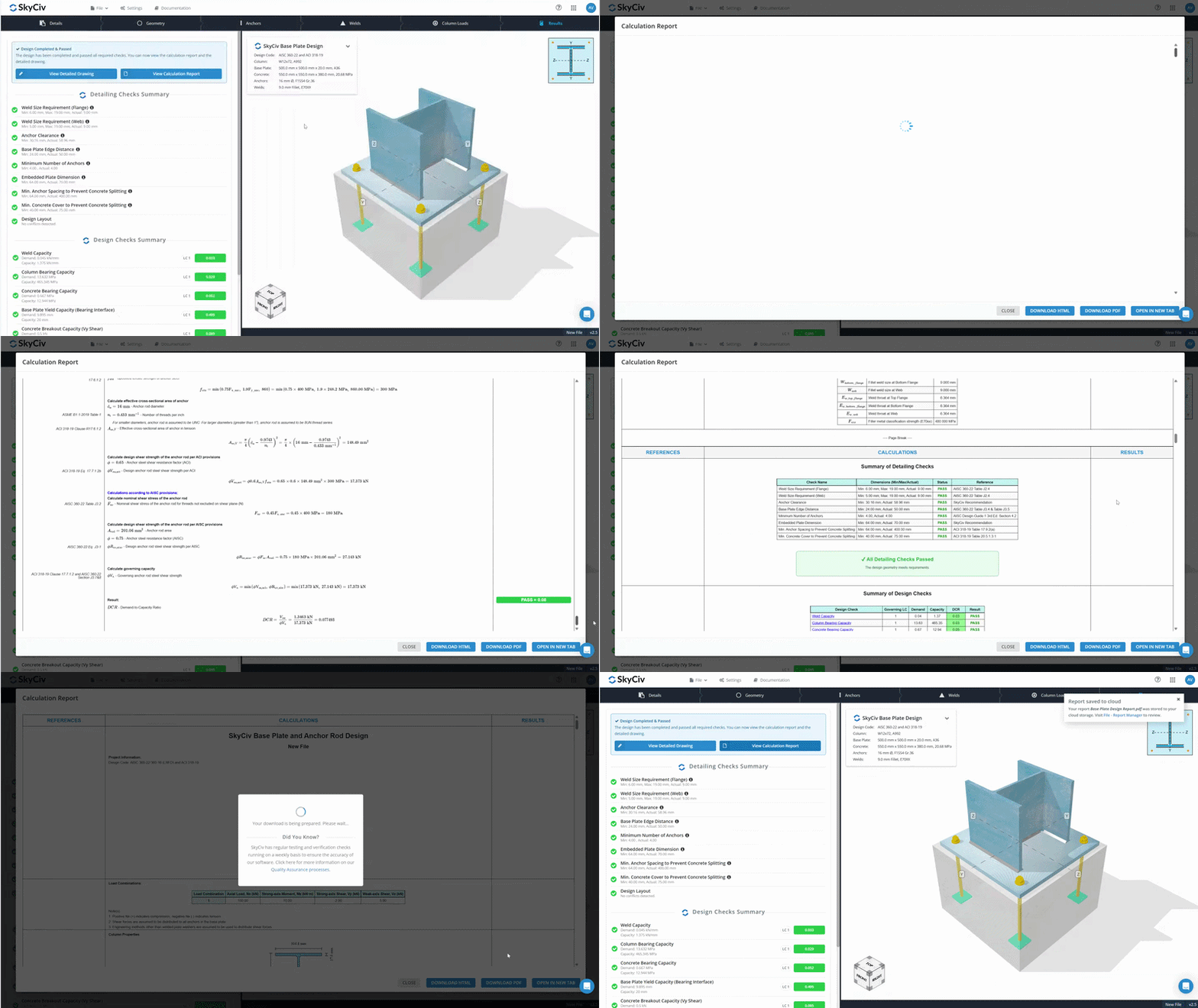
Ένα κλικ εκτελεί το πλήρες σετ επιταγών — χάλυβα, σκυρόδεμα, συγκόλληση και αγκύρωση — σε κάθε συνδυασμό φορτίου στο μοντέλο ταυτόχρονα. Ο πίνακας αποτελεσμάτων παραθέτει κάθε επιταγή με τη ζήτησή του, χωρητικότητά του, ο λόγος ζήτησης προς χωρητικότητα και ο συνδυασμός φορτίου που διέπει τον συγκεκριμένο έλεγχο, ώστε να μπορείτε να δείτε ποιος συνδυασμός οδηγεί κάθε αποτέλεσμα και όχι μόνο εάν πέρασε.
Η αναφορά υπολογισμού δημιουργείται από την ίδια εκτέλεση, χωρίς ξεχωριστό βήμα εγγραφής. Περιλαμβάνει τη βήμα προς βήμα εργασία για κάθε έλεγχο, την αναφερόμενη εξίσωση και τον αριθμό ρήτρας από τον επιλεγμένο κωδικό σας, και κλιμακωμένες απεικονίσεις της γεωμετρίας εισόδου και των επιφανειών ελέγχου αγκύρωσης. Όνομα έργου, Εταιρία, σχεδιαστής, Το αναγνωριστικό έργου και τα στοιχεία πελάτη μεταφέρονται από την καρτέλα Λεπτομέρειες στην κεφαλίδα της αναφοράς. Εξαγωγή σε PDF ή HTML.
Το σημείο εμφάνισης της πλήρους εργασίας είναι η δυνατότητα αναθεώρησης. Ένας ελεγκτής μπορεί να ακολουθήσει τον υπολογισμό γραμμή προς γραμμή και να δει τις υποθέσεις αντί να αποδεχτεί έναν αριθμό χωρητικότητας και έναν βαθμό επιτυχίας, που είναι επίσης αυτό που κάνει το προϊόν να χρησιμοποιηθεί ως αρχείο σχεδιασμού για έγκριση.
Δημιουργία αυτοματοποιημένης σχεδίασης λεπτομερειών
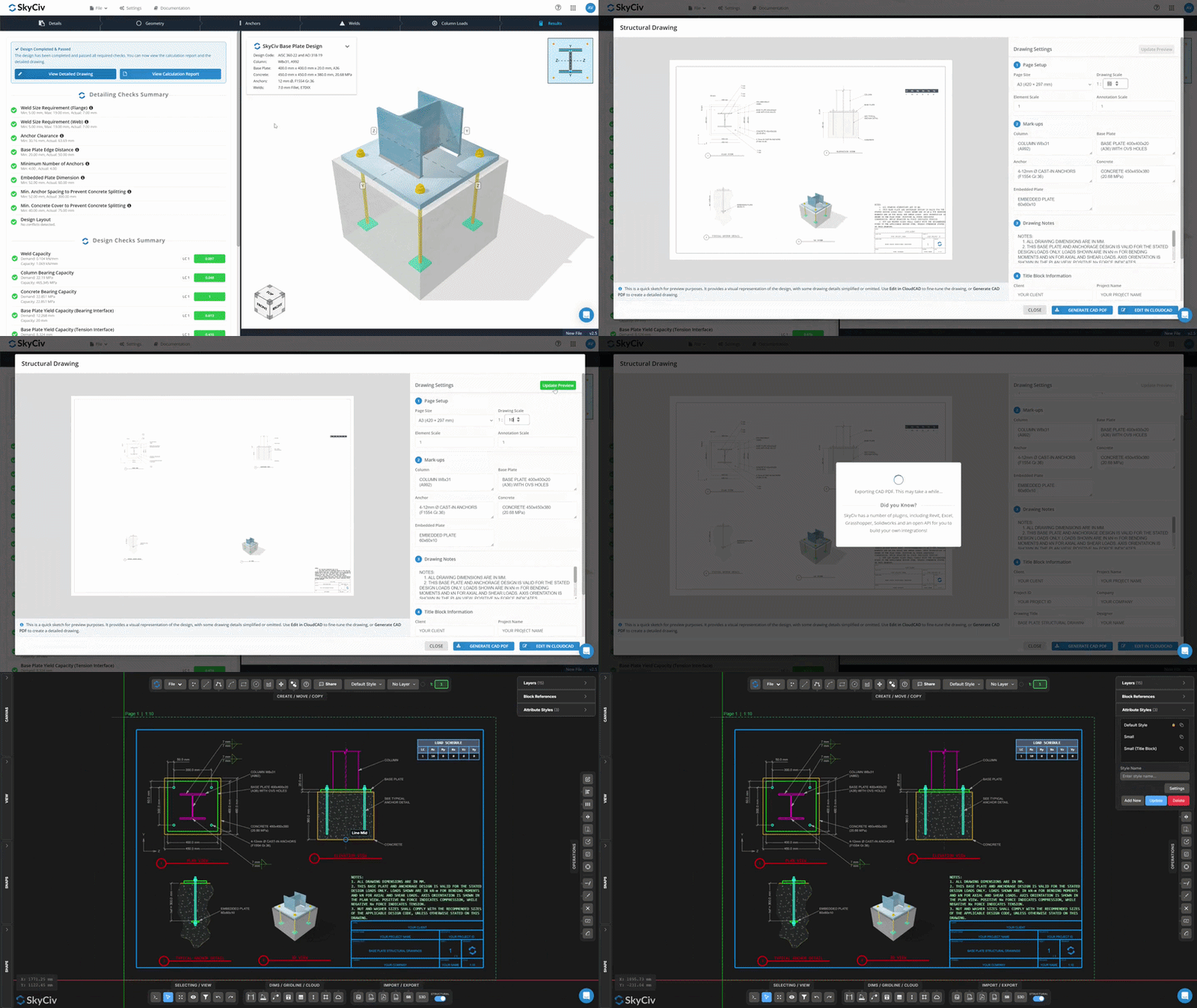
Μόλις περάσει το σχέδιο, Το ίδιο μοντέλο παράγει το σχέδιο λεπτομέρειας. Η έξοδος είναι ένα σωστό σχέδιο CAD με επίπεδα και σχολιασμούς, όχι ένα στιγμιότυπο οθόνης του μοντέλου.
Το φύλλο περιλαμβάνει κάτοψη και όψη, πλήρεις διαστάσεις, επεξηγήσεις συγκόλλησης, ένα πρόγραμμα φόρτωσης και ένα μπλοκ τίτλου. Επεξηγήσεις, Οι σημειώσεις σχεδίασης και οι πληροφορίες του μπλοκ τίτλου είναι όλα επεξεργάσιμα, το σχέδιο μπορεί να κλιμακωθεί, και είναι διαθέσιμος ένας μακρύς κατάλογος μεγεθών χαρτιού. Κατεβάστε το ως PDF έτοιμο προς έκδοση, ή ανοίξτε το SkyCiv CloudCAD για να το αναπτύξετε περαιτέρω — προσαρμόστε τα επίπεδα, προσθέστε σημειώσεις και απλώστε το φύλλο χωρίς να φύγετε από το SkyCiv.
Η εξοικονόμηση χρόνου είναι απλή: κανείς δεν ξανασχεδιάζει την πλάκα βάσης με το χέρι, που χρειάζεται ένας συντάκτης μερικές ώρες ανά λεπτομέρεια. Η εξοικονόμηση διατηρείται και μέσω αναθεωρήσεων. Όταν το πάχος της πλάκας αλλάζει ή μετακινείται μια άγκυρα, αναγεννήστε το σχέδιο και το νέο φύλλο βγαίνει με την ενημερωμένη γεωμετρία και τις διαστάσεις ήδη, αντί να στείλετε κάποιον πίσω στο αρχείο CAD για να κυνηγήσει κάθε επηρεαζόμενο σχολιασμό.
Πρόσβαση API
Οποιοδήποτε σχέδιο μπορείτε να ρυθμίσετε στην αριθμομηχανή μπορεί επίσης να εκτελεστεί μέσω προγραμματισμού μέσω του SkyCiv API, SkyCiv Renderer API αυτόνομο.βάση χώρο ονομάτων. Υποβάλετε το αντικείμενο σχεδίασης, λάβετε τα πλήρη αποτελέσματα του ελέγχου, και δημιουργήστε την αναφορά υπολογισμού χωρίς να ανοίξετε τη διεπαφή.
Μια εκτέλεση χρησιμοποιεί δύο λειτουργίες: standalone.baseplate.start για την έναρξη της συνεδρίας, στη συνέχεια standalone.baseplate.check για να υποβάλετε το σχέδιο. Γιατί απαιτούνται και τα δύο, κοστίζει κάθε ρύθμιση της πλάκας βάσης 2 Πιστώσεις API.
Το API υποστηρίζει και τις τέσσερις μεγάλες οικογένειες κωδικών — Αμερικάνικες, Αυστραλός, Καναδά και Ευρώπη — και η δομή αιτημάτων είναι η ίδια για το καθένα. Οι διαφορές μεταξύ των κωδικών περιορίζονται στους παράγοντες αντίστασης, ρυθμίσεις σχεδιασμού και αξίες υλικών, Έτσι, μια ενοποίηση που έχει δημιουργηθεί για έναν κώδικα επεκτείνεται και στους άλλους χωρίς να αναδιαρθρώνεται το ωφέλιμο φορτίο.
Η περίπτωση για το API είναι ο όγκος. Εάν σχεδιάζετε την ίδια σύνδεση σε σαράντα στήλες σε μια αποθήκη, πλάκες μεγεθών για μια σειρά προϊόντων πλαισίων τοποθέτησης, ή κατασκευή ενός διαμορφωτή που πρέπει να παράγει μια πλάκα βάσης κατά παραγγελία, Η λειτουργία τους ως παρτίδα αντικαθιστά την εργασία της ρύθμισης κάθε μοντέλου με το χέρι.
Η πλήρης αναφορά εισόδου και τα δείγματα ωφέλιμου φορτίου για κάθε κώδικα σχεδίασης βρίσκονται στο τεκμηρίωση API standalone.baseplate.
Πώς να σχεδιάσετε μια πλάκα βάσης στο SkyCiv
Πώς να μοντελοποιήσετε μια πλάκα βάσης
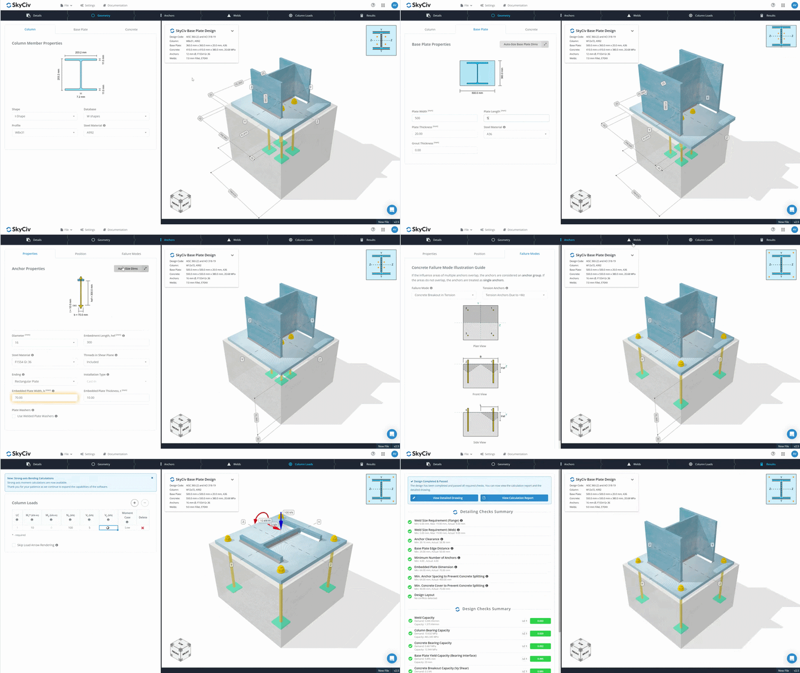
Μια πρωτιά μοντέλο πλάκας βάσης διαρκεί λιγότερο από δέκα λεπτά. Επιλέξτε έναν κώδικα σχεδίασης και ένα αρχικό πρότυπο, στη συνέχεια επεξεργαστείτε τις καρτέλες με τη σειρά.
- Λεπτομέρειες έργου. Ρυθμίστε τις μονάδες σας και εισαγάγετε το όνομα του έργου, Εταιρία, σχεδιαστής, αναγνωριστικό έργου και πελάτη. Αυτά μεταφέρονται στην αναφορά υπολογισμού και στο λεπτομερές σχέδιο, Επομένως, η συμπλήρωσή τους αποθηκεύει την επεξεργασία της αναφοράς αργότερα. Οι παράγοντες σχεδίασης και οι επιλογές ελέγχου βρίσκονται επίσης εδώ, κάτω από τις Ρυθμίσεις σχεδίασης, έχει ήδη συμπληρωθεί με τις προεπιλογές για τον κωδικό που επιλέξατε.
- Γεωμετρία. Επιλέξτε το σχήμα της στήλης — Τμήμα I, ορθογώνια ή τετράγωνο HSS, ή κυκλικό HSS — μετά επιλέξτε το προφίλ από το AISC, ΣΕ, Βάση δεδομένων AS ή CSA και ορίστε τον βαθμό, ή εισαγάγετε προσαρμοσμένα Fy και Fu. Ρυθμίστε το πλάτος της πλάκας βάσης, μήκος και πάχος, προσθέστε ενέματα αν το έχει η σύνδεση, και ορίστε τις συγκεκριμένες διαστάσεις, αντοχή σε θλίψη και αν είναι ραγισμένο ή μη. Το Auto-Size θα αναλογεί την πλάκα στη στήλη και το σκυρόδεμα στην πλάκα; λειτουργεί μόνο από γεωμετρία, Επομένως, θεωρήστε το ως σημείο εκκίνησης και όχι ως σχέδιο.
- Άγκυρες. Ρυθμίστε τη διάμετρο της άγκυρας, βαθμός και ενσωματωμένη τελική κατάσταση — ευθεία, ορθογώνιο πιάτο, κυκλική πλάκα ή άγκιστρο — μαζί με το μήκος ενσωμάτωσης έχω. Μπορείτε επίσης να επιλέξετε να χρησιμοποιήσετε συγκολλημένες ροδέλες πλακών, εάν υποστηρίζεται από τον επιλεγμένο κώδικα σχεδίασης. Η τοποθέτηση καλύπτεται στην επόμενη ενότητα.
- Συγκολλήσεις. Επιλέξτε φιλέτο ή CJP/FPBW, ρυθμίστε το υλικό συγκόλλησης και το μέγεθος των ποδιών, και προσαρμόστε την υποχώρηση στα τμήματα I για να καθαρίσετε την ακτίνα του φιλέτου. Επιλέγετε επίσης πώς η συμπίεση φτάνει στην πλάκα: μέσω των συγκολλήσεων, ή με απευθείας ρουλεμάν του τμήματος στήλης στην πλάκα, που είναι η προεπιλεγμένη και η συνήθης διάταξη όπου το άκρο της στήλης προετοιμάζεται για έδραση.
- Φορτώσεις στηλών. Εισαγάγετε συντελεστές φορτίων — αξονικά, διάτμηση και κάμψη ισχυρού άξονα. Η αξονική ακολουθεί τη σύμβαση ότι η θετική είναι η συμπίεση και η αρνητική η τάση. Προσθέστε όσους συνδυασμούς φορτίου χρειάζεται ο σχεδιασμός; κάθε έλεγχος αναφέρει ποια διέπει. Εάν η δομή έχει μοντελοποιηθεί σε SkyCiv Structural 3D, αυτές οι τιμές είναι οι αντιδράσεις υποστήριξης.
- Εκτελέστε τους ελέγχους. Η Σύνοψη λεπτομερειών ελέγχου έρχεται πρώτη. Καθαρίστε το, ή να παρακάμψετε όπου χρειάζεται, Στη συνέχεια, εκτελέστε τους ελέγχους σχεδιασμού για τον πλήρη πίνακα αποτελεσμάτων και τη λεπτομερή αναφορά υπολογισμού.
- Δημιουργήστε το λεπτομερές σχέδιο. Μόλις περάσει κάθε έλεγχος, δημιουργήσετε το σχέδιο. Εκτυπώστε το όπως είναι, στο προεπιλεγμένο στυλ και διάταξη, ή ανοίξτε το SkyCiv CloudCAD να το αναπτύξει περαιτέρω. Το CloudCAD είναι το λογισμικό σύνταξης της SkyCiv, και η επεξεργασία εκεί απαιτεί συνδρομή.
Πώς να τοποθετήσετε τις ράβδους αγκύρωσης
Η διάταξη αγκύρωσης είναι κατασκευασμένη από προκαθορισμένα μοτίβα αντί να τοποθετείται άγκυρα με άγκυρα. Επιλέξτε το μοτίβο που ταιριάζει στις λεπτομέρειές σας και η αριθμομηχανή τοποθετεί τις ράβδους συμμετρικά γύρω από τη στήλη για εσάς, που αφαιρεί την αριθμητική διάταξη και αποκλείει την ασυμμετρία πίσω από τα περισσότερα σφάλματα ρύθμισης αγκύρωσης. Τα διαθέσιμα μοτίβα εξαρτώνται από το σχήμα της στήλης:
- Στήλες I-τμήμα — Γωνίες, Μόνο φλάντζα, Μόνο Web
- Ορθογώνιες και τετράγωνες στήλες — Γωνίες, Μόνο πάνω/κάτω, Μόνο αριστερά/δεξιά, Όλες οι πλευρές
- Κυκλικές στήλες — Γωνίες
Μέσα σε ένα μοτίβο ελέγχετε τον αριθμό των αγκυρίων, την απόσταση σε κάθε κατεύθυνση και την απόσταση του άκρου από την άκρη της πλάκας. Το μοτίβο καθορίζει τη διάταξη; εσύ ορίζεις τις διαστάσεις. Πλήρως προσαρμοσμένη τοποθέτηση, που σημαίνει μεμονωμένες άγκυρες σε αυθαίρετες συντεταγμένες, δεν περιλαμβάνεται ακόμη.
Τοποθετήστε τις άγκυρές σας στη ζώνη τάσης
Το να γνωρίζετε πού να τοποθετήσετε τις άγκυρες ώστε να λειτουργούν πραγματικά υπό τάση είναι ένα από τα πιο εξαρτώμενα από την εμπειρία μέρη του σχεδιασμού της βάσης, έτσι η αριθμομηχανή το επισημαίνει για εσάς. Οι ζώνες τάσης είναι προκαθορισμένες στην πλάκα και εμφανίζονται στο μοντέλο, και όπου κάθονται ακολουθεί η συνθήκη στήριξης:
- Καρφιτσωμένες βάσεις — οι ζώνες είναι οι περιοχές που βρίσκονται πιο κοντά στις όψεις των στηλών: παράλληλα με τις φλάντζες και τον ιστό σε ένα τμήμα I, ή κατά μήκος των όψεων ενός HSS.
- Σταθερές βάσεις κάτω από κάμψη ισχυρού άξονα — οι ζώνες βρίσκονται έξω από τις φλάντζες, μεταξύ κάθε φλάντζας και του πλησιέστερου άκρου της πλάκας βάσης.
Αυτές είναι οι περιοχές όπου μια άγκυρα εμπλέκεται σε ένταση, ώστε να βρίσκονται εκεί που θέλετε οι ράβδοι σας κάθε φορά που μια θήκη φόρτωσης προκαλεί ανύψωση ή διχτυωτή τάση. Αυτές οι άγκυρες είναι που κρατούν τη στήλη κάτω, και η τοποθέτησή τους μέσα στη ζώνη διατηρεί τη διάταξη συνεπή με τον τρόπο υπολογισμού της τάσης.
Ανάβω Εμφάνιση ζωνών τάσης άγκυρας στις ρυθμίσεις του σχήματος και οι ζώνες εμφανίζονται στην πλάκα καθώς τοποθετείτε τις άγκυρες, ώστε να μπορείτε να βλέπετε τη σωστή τοποθέτηση ενώ επιλέγετε ακόμα απόσταση και αποστάσεις άκρων. Το Anchor Data Summary το επιβεβαιώνει στη συνέχεια, αναφέροντας κάθε άγκυρα με την ταυτότητά του, συντεταγμένες και αν κάθεται μέσα σε μια ζώνη.
Εάν η βάση σας φέρει καθαρή συμπίεση χωρίς θήκη ανύψωσης, Η θέση άγκυρας είναι μια λεπτομερής απόφαση και η τοποθέτηση ράβδων εκτός των ζωνών είναι απολύτως λογική. Οι ζώνες έχουν σημασία μόλις εισέλθει η ένταση στην εικόνα.
Single Anchors και Anchor Groups
Η απόσταση αγκύρωσης κάνει κάτι άλλο που αξίζει να κατανοήσετε: αποφασίζει εάν οι άγκυρές σας θα αξιολογηθούν ως μεμονωμένες άγκυρες ή ως ομαδικές.
Η διάκριση ισχύει μόνο για τους συγκεκριμένους ελέγχους. Η τάση και η διάτμηση του χάλυβα αξιολογούνται πάντα ανά άγκυρα, αφού η χωρητικότητα μιας ράβδου εξαρτάται από τη δική της επιφάνεια και βαθμό. Η χωρητικότητα του σκυροδέματος λειτουργεί διαφορετικά, επειδή εξαρτάται από τον όγκο του σκυροδέματος που μπορεί να κινητοποιήσει μια άγκυρα, και οι γειτονικές άγκυρες ανταγωνίζονται για το ίδιο σκυρόδεμα.
Αυτό που διαχωρίζει τις δύο περιπτώσεις είναι εάν οι προβαλλόμενες επιφάνειες αστοχίας επικαλύπτονται. Άγκυρες που έχουν μεγάλη απόσταση, ή ρηχά ενσωματωμένα, κώνους έργου που παραμένουν μακριά ο ένας από τον άλλο, οπότε κάθε άγκυρα ελέγχεται από μόνη της. Φέρτε τα πιο κοντά ή βάλτε τα πιο βαθιά και οι κώνοι τέμνονται. Από εκείνο το σημείο το σκυρόδεμα διέπει την ικανότητα ολόκληρης της ομάδας, και η χωρητικότητα της ομάδας δεν είναι το άθροισμα των επιμέρους χωρητικοτήτων αγκύρωσης.
Οι κωδικοί χρησιμοποιούν ξεχωριστές εξισώσεις για τις δύο περιπτώσεις. Υπό ACI 318-19, Η διάσπαση τάσης για μία μόνο άγκυρα είναι Ncb; για μια ομάδα γίνεται Ncbg, που λειτουργεί από τη συνδυασμένη προβαλλόμενη περιοχή και προσθέτει έναν παράγοντα τροποποίησης εκκεντρότητας για να ληφθεί υπόψη η τάση που εφαρμόζεται από το κέντρο της ομάδας. Η διάτμηση και η έκρηξη στο πλάγιο πρόσωπο ακολουθούν το ίδιο μοτίβο, το καθένα με τη δική του ομαδική μορφή. Η έξοδος άγκυρας είναι η εξαίρεση: αξιολογείται πάντα ανά άγκυρα, αφού διέπεται από έδραση στο ενσωματωμένο άκρο παρά από τσιμεντένιο κώνο.
Η αριθμομηχανή καθορίζει ποια περίπτωση ισχύει από τη γεωμετρία σας και εμφανίζει τις προβλεπόμενες περιοχές αστοχίας στο μοντέλο, Έτσι, η συμπεριφορά της ομάδας είναι κάτι που μπορείτε να δείτε μαζί με τους αριθμούς καθώς ορίζετε την απόσταση, αποστάσεις ενσωμάτωσης και ακμών.
Για πληρέστερη αντιμετώπιση κάθε τρόπου αποτυχίας ACI και τι το οδηγεί, δείτε το Οδηγός SkyCiv για ελέγχους αγκύρωσης ACI.
Πώς να εκτελέσετε τον αρχικό υπολογισμό της ακαμψίας περιστροφής για τον σχεδιασμό του Ευρωκώδικα
Η ανάλυση πλαισίου συνήθως αντιμετωπίζει μια βάση στήλης είτε ως καρφιτσωμένη είτε ως πλήρως στερεωμένη. Οι πραγματικές πλάκες βάσης πέφτουν μεταξύ των δύο. ΣΕ 1993-1-8 Επομένως, αναμένει μια σταθερή βάση να δικαιολογείται από την ακαμψία της σύνδεσης.
Για σχέδια Ευρωκώδικα με σταθερή βάση, η αριθμομηχανή υπολογίζει την αρχική περιστροφική ακαμψία Sj,ini της σύνδεσης και την ταξινομεί στα όρια του κώδικα. Η ταξινόμηση εκφράζεται ως πολλαπλασιαστής στο EI/L της ίδιας της στήλης, με όρια στο κάτω και πάνω όριο του κώδικα, έτσι η έξοδος σας λέει άμεσα εάν η βάση μπορεί να θεωρηθεί άκαμπτη, ημιάκαμπτο ή ονομαστικά καρφιτσωμένο στο μοντέλο ανάλυσης.
Απαιτούνται δύο είσοδοι για την εκτέλεση του ελέγχου:
- Δώστε ύψος στήλης, εισάγεται στην καρτέλα Γεωμετρία. Η ταξινόμηση συγκρίνει την ακαμψία σύνδεσης με την ακαμψία κάμψης της στήλης που υποστηρίζει, έτσι η ίδια πλάκα βάσης μπορεί να είναι άκαμπτη κάτω από μια κοντή στιβαρή στήλη και ημιάκαμπτη κάτω από μια ψηλή λεπτή στήλη.
- Παρέχετε τόσο ροπή όσο και αξονικό φορτίο στη θήκη φορτίου. Η περιστροφική ακαμψία είναι μια ιδιότητα περιστροφής ροπής, οπότε μια καθαρά αξονική περίπτωση δεν έχει περιστροφή για ταξινόμηση. Ούτε μια υπόθεση μόνο για στιγμή δεν λειτουργεί. Η διατύπωση του Ευρωκώδικα λειτουργεί από την εκκεντρότητα του φορτίου, e = M/N, που δεν έχει πεπερασμένη τιμή όταν το αξονικό φορτίο είναι μηδέν. Και τα δύο εξαρτήματα πρέπει να υπάρχουν για να έχει ακαμψία η σύνδεση για αναφορά.
Εάν το αποτέλεσμα επανέλθει κάτω από το άκαμπτο όριο, οι μοχλοί είναι μια πιο χοντρή πλάκα, ένας μακρύτερος μοχλοβραχίονας μεταξύ της ομάδας αγκύρωσης και της ζώνης συμπίεσης, ή μια πιο άκαμπτη διάταξη αγκύρωσης. Το καθένα λύνεται ξανά αμέσως, οπότε το αποτέλεσμα μιας αλλαγής απέχει λίγα δευτερόλεπτα παρά η ανακατασκευή του μοντέλου.
Χρειάζεστε περισσότερη λειτουργικότητα?

Διαισθητική διασύνδεση
Μας είναι εύκολο να μάθουμε, ισχυρό στη χρήση, Η διαισθητική διεπαφή σάς επιτρέπει να έχετε γρήγορη πρόσβαση σε όλες τις λειτουργίες που χρειάζεστε. Γεμάτο με έξυπνες λειτουργίες όπως το εργαλείο στυλό, Επανάληψη / Καθρέφτης, και Μαζική επεξεργασία. Το περιεχόμενό σας πηγαίνει εδώ

Ολοκληρωμένη Υποστήριξη Κώδικα Σχεδιασμού
Το λογισμικό μας υποστηρίζει μια ολοκληρωμένη σειρά από χάλυβα, ξύλο, και συγκεκριμένοι κώδικες σχεδιασμού συμπεριλαμβανομένου του AISC, ΣΕ, AISI, NDS, ΟΠΩΣ ΚΑΙ, και CSA.

Τεχνολογία API
Το SkyCiv είναι μια προσαρμοσμένη λύση που διαθέτει απρόσκοπτες ενσωματώσεις, εύκολες υλοποιήσεις, αυτοματοποιημένες αναφορές και επεκτάσιμη σχεδίαση και αρχιτεκτονική.

24/7 Υποστήριξη πελατών
Το SkyCiv είναι μια προσαρμοσμένη λύση που διαθέτει απρόσκοπτες ενσωματώσεις, εύκολες υλοποιήσεις, αυτοματοποιημένες αναφορές και επεκτάσιμη σχεδίαση και αρχιτεκτονική.

