Η SkyCiv Load Generator πρόσθεσε πρόσφατα τον υπολογισμό σεισμικού φορτίου σύμφωνα με το ASCE7-16. Αυτό περιλαμβάνει την ενσωμάτωση των σεισμικών δεδομένων USGS και την επεξεργασία τους για τη δημιουργία της σεισμικής διάτμησης βάσης χρησιμοποιώντας την ενότητα 12.8 Ισοδύναμη πλευρική διαδικασία. Σε αυτό το άρθρο, θα βουτήξουμε βαθύτερα στη διαδικασία υπολογισμού των σεισμικών φορτίων για ένα κτίριο χρησιμοποιώντας ASCE 7-16.
Το SkyCiv ενσωμάτωσε τώρα τα σεισμικά δεδομένα του ιστότοπου από το USGS Web API. Δοκιμάστε μας Γεννήτρια φορτίου SkyCiv!
Δεδομένα δομής
Σε αυτό το παράδειγμα, θα χρησιμοποιήσουμε τα παρακάτω δεδομένα για τον υπολογισμό του σεισμικού φορτίου:
Τραπέζι 1. Στοιχεία κτιρίου που απαιτούνται για τον υπολογισμό του σεισμικού φορτίου μας.
| Τοποθεσία | 8050 SW Beaverton Hillsdale Hwy, Πόρτλαντ, Ή 97225, ΗΠΑ |
| Χωρητικότητα | Κτίριο κατοικιών |
| Διαστάσεις | 64 πόδια (4 όρμους) × 104 πόδια (6 όρμους) σε σχέδιο Ύψος δαπέδου 15 πόδια Ύψος στέγης στο υψόμετρο. 75 πόδια Ταράτσα Στήλη: 20″x20″ Δέσμη: 14″x20″ Πλάκα: 8″ πάχος |
| Φόρτωση | Βάρος μονάδας σκυροδέματος : 156 pcf Υπερτιθέμενο νεκρό φορτίο (στο πάτωμα): 100 psf Υπερτιθέμενο νεκρό φορτίο (στη στέγη): 50 psf |
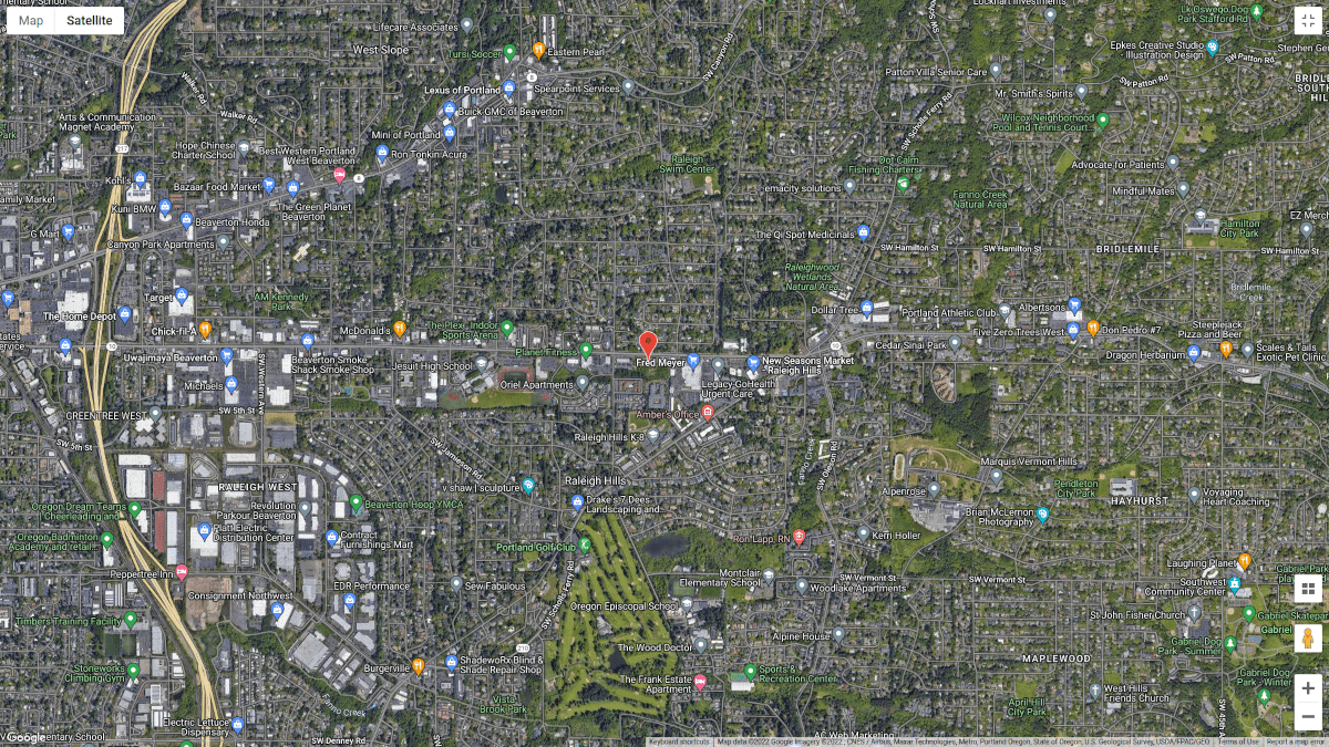
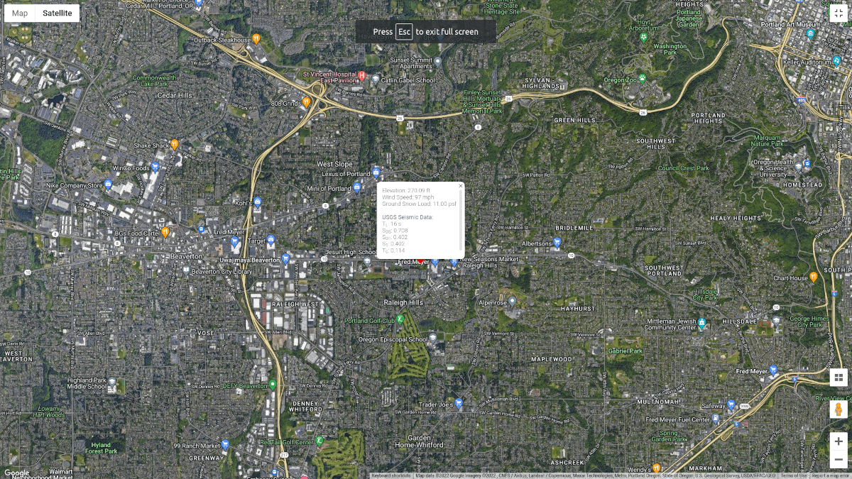
Φιγούρα 1. Τοποθεσία ιστότοπου (από τους Χάρτες Google).
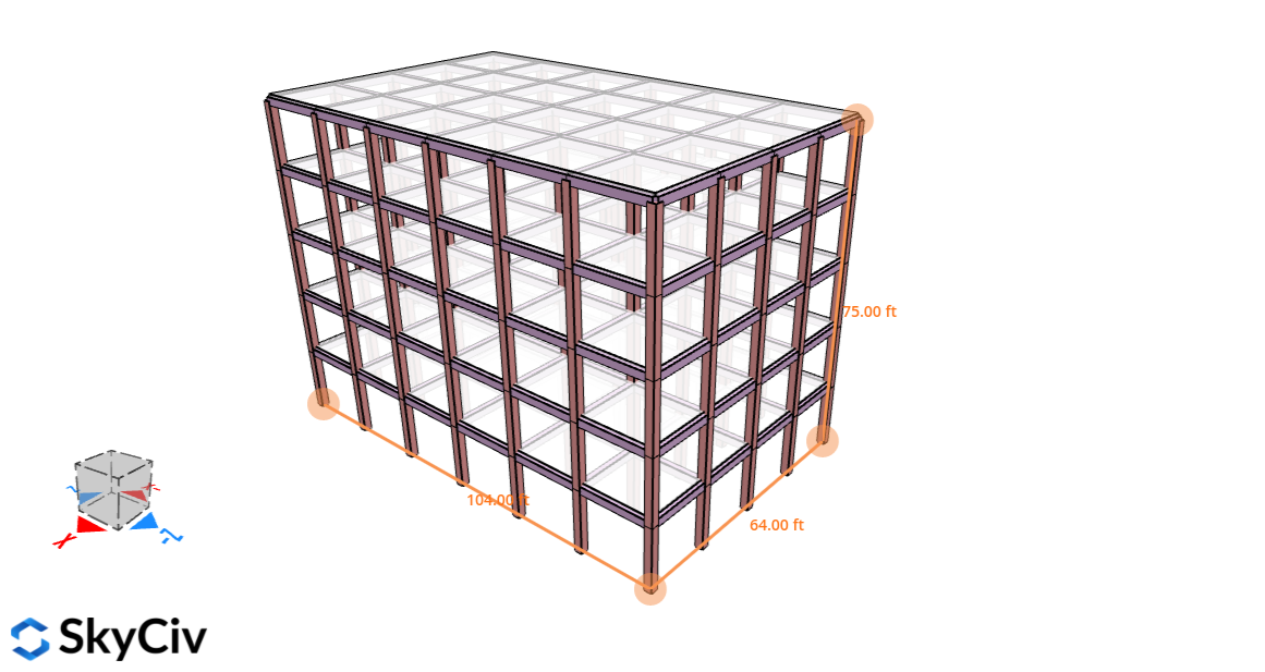
Φιγούρα 2. Δομή για αυτό το παράδειγμα.
Σεισμικά δεδομένα USGS
Το USGS διαθέτει ένα σεισμικά δεδομένα τοποθεσίας ανοιχτού κώδικα που μπορεί να χρησιμοποιηθεί από το Design Web Services API. Σε αυτόν τον υπολογισμό, θα χρειαστούμε μόνο τα ακόλουθα δεδομένα:
- \({μικρό}_{Δ1}\) είναι οι παράμετροι επιτάχυνσης της φασματικής απόκρισης σχεδιασμού σε μια περίοδο 1.0 μικρό
- \({μικρό}_{1}\) είναι η χαρτογραφημένη μέγιστη θεωρούμενη παράμετρος επιτάχυνσης φασματικής απόκρισης σεισμού
- \({μικρό}_{DS}\)είναι η παράμετρος επιτάχυνσης φασματικής απόκρισης σχεδιασμού στο εύρος μικρής περιόδου
- \({Τ}_{μεγάλο}\) είναι η μακροχρόνια μεταβατική περίοδος
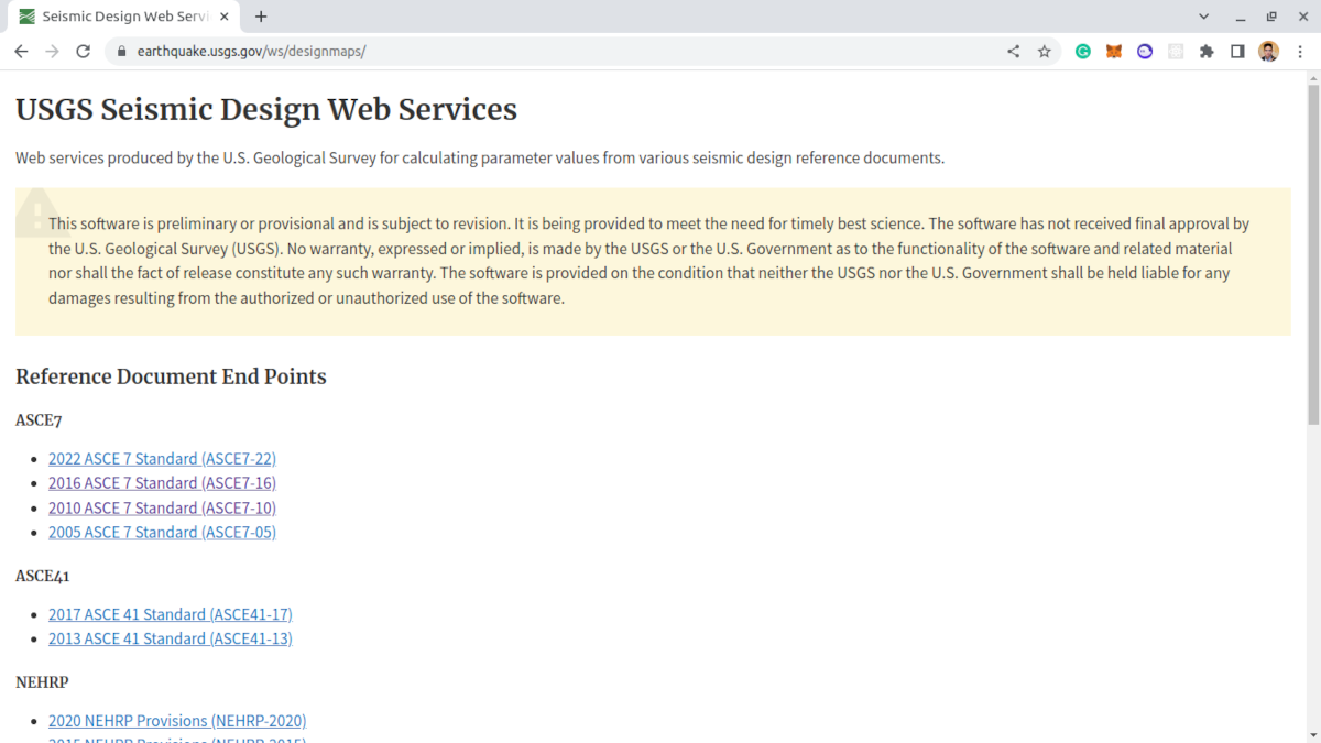
Φιγούρα 3. Υπηρεσίες Web USGS Seismic Design.
Για να ζητήσουμε τα παραπάνω δεδομένα θα χρειαστούμε τα ακόλουθα δεδομένα:
- Γεωγραφικό πλάτος, Γεωγραφικό μήκος που μπορούμε να λάβουμε από τους Χάρτες Google
- Κατηγορία κινδύνου της δομής βάσει Ενότητας 1.5 του ASCE 7-16
- Κατηγορία ιστότοπου βάσει πίνακα 20.3-1 του ASCE 7-16
Διαδικασία Ισοδύναμης Πλευρικής Δύναμης
Η διάτμηση βάσης σεισμικού σχεδιασμού μπορεί να υπολογιστεί χρησιμοποιώντας την Εξίσωση 12.8-1 του ASCE 7-16:
\( V = {ντο}_{μικρό} Δ \) (Εξ. 12.8-1)
Οπου:
\( Β \) είναι η διάτμηση βάσης σεισμικού σχεδιασμού
\( {ντο}_{μικρό} \) είναι ο συντελεστής σεισμικής απόκρισης με βάση το Τμήμα 12.8.1.1
\( Δ \) είναι το αποτελεσματικό σεισμικό βάρος σύμφωνα με την Ενότητα 12.7.2
Ο τύπος για τον προσδιορισμό του συντελεστή σεισμικής απόκρισης είναι:
\( {ντο}_{μικρό} = frac{{μικρό}_{DS}}{ \frac { Ρ }{ {Εγώ}_{μι} } } \) (Εξ. 12.8-2)
Οπου:
\( {μικρό}_{DS} \) είναι η παράμετρος επιτάχυνσης φασματικής απόκρισης σχεδιασμού στο εύρος μικρής περιόδου (από δεδομένα USGS)
\( Ρ \) είναι ο παράγοντας τροποποίησης απόκρισης σύμφωνα με τον Πίνακα 12.2-1
\( {Εγώ}_{μι} \) είναι ο παράγοντας σημασίας που καθορίζεται από την Ενότητα 11.5.1
Ωστόσο, πρέπει να ικανοποιήσουμε τις Εξισώσεις 12.8-3 προς το 12.8-6:
Η αξία του \({ντο}_{μικρό}\) δεν πρέπει να υπερβαίνει 12.8-3 ή 12.8-4
Για \( T ≤ {Τ}_{μεγάλο}\):
\({ντο}_{μικρό,Μέγιστη} = frac { {μικρό}_{Δ1}}{ \frac{Τ Ρ}{{Εγώ}_{μι}}} \) (Εξ. 12.8-3)
Για \( Τ > {Τ}_{μεγάλο}\) :
\({ντο}_{μικρό,Μέγιστη} = frac { {μικρό}_{Δ1} {Τ}_{μεγάλο} }{ \frac{ {Τ}^{2} Ρ}{{Εγώ}_{μι}}} \) (Εξ. 12.8-4)
Εξάλλου, \( {ντο}_{μικρό} \) δεν θα είναι μικρότερη από την Εξίσωση 12.8-5
\( {ντο}_{μικρό,ελάχ} = 0.044 {μικρό}_{DS} {Εγώ}_{μι} ή σχισμές προεξέχουν πάνω από το ύψος των χαρακτηριστικών του ανάνερου εδάφους σε απόσταση 2 mi 0.01 \) (Εξ. 12.8-5)
Επιπλέον, για κατασκευές που βρίσκονται όπου \( {μικρό}_{1} ≥ 0,6 g):
\( {ντο}_{μικρό,ελάχ} = 0.5 \frac {{μικρό}_{1}} { \frac{Ρ}{{Εγώ}_{μι}}} \) (Εξ. 12.8-6)
Οπου
\( {μικρό}_{Δ1} \) είναι η παράμετρος επιτάχυνσης φασματικής απόκρισης σχεδιασμού στην περίοδο του 1.0 μικρό (από δεδομένα USGS)
\( Τ \) είναι η θεμελιώδης περίοδος της δομής
\( {Τ}_{μεγάλο} \) είναι η μακροχρόνια μεταβατική περίοδος (από δεδομένα USGS)
\( {μικρό}_{1} \) είναι η χαρτογραφημένη μέγιστη θεωρούμενη παράμετρος επιτάχυνσης φασματικής απόκρισης σεισμού (από δεδομένα USGS)
Αφού υπολογίσουμε την τιμή της σεισμικής διάτμησης βάσης \( Β \), πρέπει να κατανείμουμε τις δυνάμεις κατά μήκος του ύψους της κατασκευής χρησιμοποιώντας το Section 12.8.3 του ASCE 7-16. Σε αυτό το παράδειγμα, θα υποθέσουμε ότι η δομή δεν έχει κάθετες ή οριζόντιες ανωμαλίες.
\( {φά}_{Χ} ={ντο}_{vx} Β \) (Εξ. 12.8-11)
\( {ντο}_{vx} = frac {{β}_{Χ}{{η}_{Χ}}^{κ}} { \άθροισμα_{= Μικτό εμβαδόν διατομής}^ n{β}_{Εγώ}{{η}_{Εγώ}}^{κ}} \) (Εξ. 12.8-12)
Οπου
\( {ντο}_{vx} \) είναι ο συντελεστής κατακόρυφης κατανομής
\( {β}_{Εγώ} \) και \( {β}_{Χ} \) είναι το μέρος του συνολικού ενεργού σεισμικού βάρους της κατασκευής \( Δ \) που βρίσκεται ή εκχωρείται σε επίπεδο Εγώ ή Χ
\( {η}_{Εγώ} \) και \( {η}_{Χ} \) είναι το ύψος από τη βάση στο επίπεδο Εγώ ή Χ
\( κ \) ορίζεται ως εξής:
- \( k = 1 \) για κατασκευές με \( T ≤ 0.5 μικρό)
- \( k = 2 \) για κατασκευές με \( T ≥ 2.5 μικρό)
- γραμμική παρεμβολή του \( κ \) Για \( 0.5 < Τ < 2.5 μικρό \)
Επιπλέον, Οι δυνάμεις διαφράγματος δαπέδου και οροφής μπορούν να προσδιοριστούν χρησιμοποιώντας το Τμήμα 12.10.1 του ASCE 7-16. Η δύναμη σχεδιασμού μπορεί να υπολογιστεί χρησιμοποιώντας εξισώσεις 12.10-1 προς το 12.10-3:
\( {φά}_{px} = frac { \άθροισμα_{i=x}^ n {φά}_{Εγώ}} { \άθροισμα_{i=x}^ n {β}_{Εγώ} }{β}_{px} \) (Εξ. 12.10-1)
\( {φά}_{px,ελάχ} = 0.2 {μικρό}_{DS}{Εγώ}_{μι}{β}_{px} \) (Εξ. 12.10-2)
\( {φά}_{px,Μέγιστη} = 0.4 {μικρό}_{DS}{Εγώ}_{μι}{β}_{px} \) (Εξ. 12.10-3)
Οπου
\( {φά}_{px} \) είναι η δύναμη σχεδιασμού του διαφράγματος σε επίπεδο Χ
\( {φά}_{Εγώ} \) είναι η δύναμη σχεδιασμού που εφαρμόζεται σε επίπεδο Εγώ
\( {β}_{Εγώ} \) είναι το βάρος παραπόταμος στο επίπεδο Εγώ
\( {β}_{px} \) είναι το βάρος παραπόταμος του διαφράγματος σε επίπεδο Χ
Θα βουτήξουμε βαθύτερα σε αυτές τις παραμέτρους παρακάτω και θα εφαρμόσουμε την ιδέα στη δομή μας.
Συντελεστής σημασίας, \( {Εγώ}_{μι} \)
Ο παράγοντας σημασίας, \( {Εγώ}_{μι} \), για τη δομή μπορεί να προσδιοριστεί από την Ενότητα 11.5.1 που δείχνει στον Πίνακα 1.5-2 του ASCE 7-16.
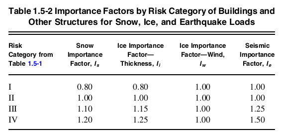
Φιγούρα 4. Τραπέζι 1.5-2 του ASCE 7-16 υποδεικνύοντας τιμές συντελεστών σημασίας ανά Κατηγορία Κινδύνου.
Δεδομένου ότι η δομή εμπίπτει κάτω Κατηγορία κινδύνου II, τον αντίστοιχο παράγοντα σημασίας \( ΕΓΩ_{μι} \) είναι ίσο με 1.0 με βάση τον Πίνακα 1.5-2.
\( {Εγώ}_{μι} = 1.0 \)
Συντελεστής Τροποποίησης Απόκρισης, \( Ρ \)
Ο παράγοντας τροποποίησης απόκρισης, \( Ρ \), μπορεί να προσδιοριστεί από τον Πίνακα 12.2-1 ανάλογα με το δομικό σύστημα που χρησιμοποιείται. Σε αυτό το παράδειγμα, θα υποθέσουμε ότι το δομικό σύστημα που χρησιμοποιείται είναι “Ειδικά Ρυπτοσυστήματα από Οπλισμένο Σκυρόδεμα” και για τις κατευθύνσεις Χ και Ζ. Από αυτό, μπορούμε να προσδιορίσουμε αυτή την τιμή \( Ρ \) είναι ίσο με 8 σύμφωνα με τον Πίνακα 12.2-1.
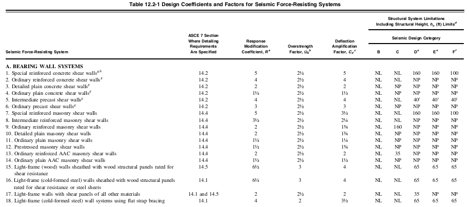
Φιγούρα 5. Περικομμένες τιμές του πίνακα 12.2-1 του ASCE 7-16 υποδεικνύοντας Συντελεστή Τροποποίησης Απόκρισης, \( Ρ \), ανά δομικό σύστημα.
Κατηγορία τοποθεσίας
Να υπολογίσουμε για το σεισμικό μας φορτίο, η τοποθεσία που θα χρησιμοποιήσουμε είναι Ράλεϊ Χιλς, Πόρτλαντ, Ή, ΗΠΑ με βάση τα σεισμικά φορτία: Οδηγός για τις Διατάξεις Σεισμικού Φορτίου του ASCE 7-16 (Οι Charney et al., 2020) που ταξινομείται ως Κατηγορία τοποθεσίας Γ.
Σεισμικά δεδομένα USGS
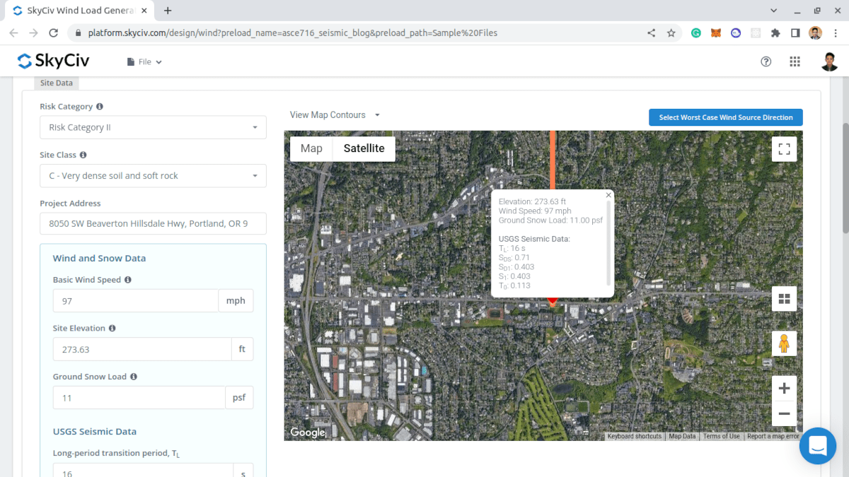
.Τα σεισμικά δεδομένα του USGS για την τοποθεσία είναι τα ακόλουθα:
Το SkyCiv ενσωμάτωσε τώρα τα σεισμικά δεδομένα του ιστότοπου από το USGS Web API. Δοκιμάστε μας Γεννήτρια φορτίου SkyCiv!
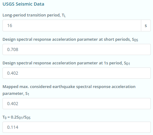
Φιγούρα 6. Σεισμικά δεδομένα τοποθεσίας από τις υπηρεσίες Web USGS.
\({μικρό}_{Δ1} = 0.402 \)
\({μικρό}_{1} = 0.402 \)
\({μικρό}_{DS} = 0.708 \)
\({Τ}_{μεγάλο} = 16 μικρό \)
\({Τ}_{0} = 0.114 \)
Κατηγορία Σεισμικού Σχεδιασμού
Ενότητα 11.6 του ASCE 7-16 λεπτομερώς πώς η διαδικασία για τον προσδιορισμό της Κατηγορίας Σεισμικής Σχεδιασμού της κατασκευής με βάση την Κατηγορία Κινδύνου και την Κατηγορία Θέσης για την κατασκευή.
- Για \({μικρό}_{1} ή σχισμές προεξέχουν πάνω από το ύψος των χαρακτηριστικών του ανάνερου εδάφους σε απόσταση 2 mi 0.75 \) και κατηγορία κινδύνου Ι, ΙΙ, ή III, η Κατηγορία Σεισμικού Σχεδιασμού θα εκχωρηθεί στην Κατηγορία Σεισμικού Σχεδιασμού Ε
- Για \({μικρό}_{1} ή σχισμές προεξέχουν πάνω από το ύψος των χαρακτηριστικών του ανάνερου εδάφους σε απόσταση 2 mi 0.75 \) και Κατηγορία Κινδύνου IV, η Κατηγορία Σεισμικού Σχεδιασμού θα εκχωρηθεί στην Κατηγορία Σεισμικής Σχεδιασμού F
- Σε διαφορετική περίπτωση, Τραπέζι 11.6-1 Υπολογισμένος συντελεστής εξωτερικής πίεσης 11.6-2 θα χρησιμοποιηθούν, όποιο είναι πιο σοβαρό.
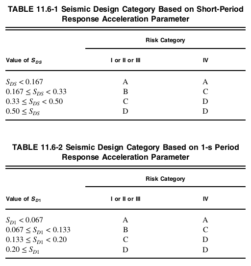
Φιγούρα 7. Κατηγορία σεισμικής σχεδίασης από το Τμήμα 11.6 του ASCE 7-16.
Για αυτήν τη δομή, με την κατηγορία κινδύνου II, \({μικρό}_{Δ1} = 0.402 \), και \({μικρό}_{DS} = 0.708 \) η Κατηγορία Σεισμικού Σχεδιασμού είναι Δ με βάση και τους δύο πίνακες 11.6-1 και 11.6-2 του ASCE 7-16. Η Κατηγορία Σεισμικού Σχεδιασμού θα χρησιμοποιηθεί για τον συντελεστή πλεονασμού \( ρ \) στον υπολογισμό των δυνάμεων σχεδιασμού του διαφράγματος.
Θεμελιώδης Περίοδος της Δομής \( Τ \)
Η θεμελιώδης περίοδος μιας δομής μπορεί να προσδιοριστεί από την τροπική ανάλυση της δομής. ASCE 7-16 επιτρέπει την προσέγγιση της θεμελιώδους περιόδου μιας δομής χρησιμοποιώντας το Τμήμα 12.8.2.1.
\( {Τ}_{ένα} = {ντο}_{τ} {{η}_{ν}}^{Χ} \)
Οπου \( {η}_{ν} \) είναι το δομικό ύψος της κατασκευής (κατακόρυφη απόσταση από τη βάση μέχρι το υψηλότερο επίπεδο του αντισεισμικού συστήματος της κατασκευής), και \( {ντο}_{τ} \) και \( Χ \) μπορεί να προσδιοριστεί από τον Πίνακα 12.8-2.
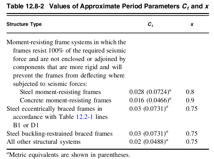
Φιγούρα 8. Τιμές του \( {ντο}_{τ} \) και \( Χ \) από τον πίνακα 12.8-2 του ASCE 7-16.
Δεδομένου ότι η δομή είναι ένα πλαίσιο που αντέχει στη ροπή από σκυρόδεμα:
\( {ντο}_{τ} = 0.016\)
\( x = 0.9\)
Επομένως, χρησιμοποιώντας το ύψος της δομής \( {η}_{ν} \) ίσο με 75 πόδια, την κατά προσέγγιση θεμελιώδη περίοδο της δομής \( {Τ}_{ένα} \) μπορεί να καθοριστεί:
\( {Τ}_{ένα} = {ντο}_{τ} {{η}_{ν}}^{Χ} = (0.016) {(75)}^{0.9}\)
\( Τ = {Τ}_{ένα} = 0.7792 μικρό)
Συντελεστής Σεισμικής Απόκρισης \({ντο}_{μικρό}\)
Από τις παραπάνω τιμές, μπορούμε ήδη να υπολογίσουμε για τον Συντελεστή Σεισμικής Απόκρισης \({ντο}_{μικρό}\):
\( {ντο}_{μικρό} = frac{ {μικρό}_{DS} }{ \frac {Ρ}{{Εγώ}_{μι}} } = frac{ 0.402 }{ \frac {8}{1.0} } \)
\( {ντο}_{μικρό} = 0.0885\)
Από \( T ≤ {Τ}_{μεγάλο}\):
\({ντο}_{μικρό,Μέγιστη} = frac { {μικρό}_{Δ1}}{ \frac{Τ Ρ}{{Εγώ}_{μι}}} = frac { (0.402)}{ \frac{(0.7792)(8)}{(1.0)}} \)
\({ντο}_{μικρό,Μέγιστη} = 0.0645 \)
Επιπλέον, η ελάχιστη τιμή του \( {ντο}_{μικρό} \) δεν πρέπει να είναι μικρότερη από:
\( {ντο}_{μικρό,ελάχ} = 0.044 {μικρό}_{DS} {Εγώ}_{μι} ή σχισμές προεξέχουν πάνω από το ύψος των χαρακτηριστικών του ανάνερου εδάφους σε απόσταση 2 mi 0.01 \)
\( {ντο}_{μικρό,ελάχ} = 0.044 (0.402) (1.0) ή σχισμές προεξέχουν πάνω από το ύψος των χαρακτηριστικών του ανάνερου εδάφους σε απόσταση 2 mi 0.01 \)
\( {ντο}_{μικρό,ελάχ} = 0.0312 \)
Η τελική τιμή του \( {ντο}_{μικρό} \) που θα χρησιμοποιηθούν στον υπολογισμό είναι:
\( {ντο}_{μικρό} = 0.0645\)
Αποτελεσματικό σεισμικό βάρος \( Δ \)
Σε αυτό το παράδειγμα, Θα υπολογίσουμε το πραγματικό σεισμικό βάρος χρησιμοποιώντας το νεκρό και υπερτιθέμενο νεκρό φορτίο που εφαρμόζεται στα δάπεδα. Εξωτερικοί και εσωτερικοί τοίχοι θεωρείται ότι ενσωματώνονται στο υπερτιθέμενο νεκρό φορτίο δαπέδου ίσο με 100 psf. Χρησιμοποιώντας σκυρόδεμα μοναδιαίο βάρος ίσο με 156 lb/cu.ft.:
Για τυπικό επίπεδο δαπέδου (εξαιρουμένων των επιπέδων εδάφους και στέγης):
Στήλη: Τυπικό ύψος ορόφου x επιφάνεια διατομής x μονάδα βάρους σκυροδέματος x συνολικός αριθ. των στηλών = 15 ft x 156 lb/cu.ft. Χ (20″x20″) Χ 35 = 227.5 kips
Πλάκα: Επιφάνεια δαπέδου x πάχος x μονάδα βάρους σκυροδέματος = 64 πόδια (104 πόδια) x 8″ Χ 156 lb/cu.ft. = 692.224 kips
Δοκοί: Συνολικό μήκος x επιφάνεια διατομής x μονάδα βάρους σκυροδέματος = 968 ft x 156 lb/cu.ft. Χ (14″x20″) = 293.627 kips
Υπερτιθέμενο νεκρό φορτίο: Επιφάνεια δαπέδου x φορτίο = 64 πόδια (104 πόδια) Χ 100 psf= 665.6 kips
Συνολικό νεκρό φορτίο ανά επίπεδο: 1878.951 kips
Για επίπεδο στέγης:
Στήλη: Τυπικό ύψος ορόφου x επιφάνεια διατομής x μονάδα βάρους σκυροδέματος x συνολικός αριθ. των στηλών = 7.5 ft x 156 lb/cu.ft. Χ (20″x20″) Χ 35 = 113.75 kips
Πλάκα: Επιφάνεια δαπέδου x πάχος x μονάδα βάρους σκυροδέματος = 64 πόδια (104 πόδια) x 8″ Χ 156 lb/cu.ft. = 692.224 kips
Δοκοί: Συνολικό μήκος x επιφάνεια διατομής x μονάδα βάρους σκυροδέματος = 968 ft x 156 lb/cu.ft. Χ (14″x20″) = 293.627 kips
Υπερτιθέμενο νεκρό φορτίο: Επιφάνεια δαπέδου x φορτίο = 64 πόδια (104 πόδια) Χ 50 psf= 332.8 kips
Συνολικό νεκρό φορτίο στο επίπεδο της οροφής: 1432.401 kips
Συνοψίζοντας:
| Οροφος | Ανύψωση, πόδια | Βάρος, wx, kips |
| Στέγη | 75 | 1432.401 |
| 5ου επιπέδου | 60 | 1878.951 |
| 4ου επιπέδου | 45 | 1878.951 |
| 33ο επίπεδο | 30 | 1878.951 |
| 2ου επιπέδου | 15 | 1878.951 |
| Αποτελεσματικό σεισμικό βάρος, Δ | 8948.203 | |
\( W = 8949.203 kips)
Σεισμική διάτμηση βάσης \( Β \)
Χρησιμοποιώντας εξίσωση 12.8-1 του ASCE 7-16, μπορεί να υπολογιστεί η διάτμηση της σεισμικής βάσης:
\( V = {ντο}_{μικρό} W = (0.0645)(8948.203) \)
\( V = 577.159 kips \)
Κατακόρυφη Κατανομή Σεισμικών Δυνάμεων \( {φά}_{Χ} \)
Πρέπει να κατανείμουμε το σεισμικό φορτίο σε όλη την κατασκευή. Δεδομένου ότι η θεμελιώδης περίοδος της δομής είναι \( Τ = {Τ}_{ένα} = 0.7792 μικρό), επομένως:
\( k = 1.1396\)
Για τον υπολογισμό της σεισμικής δύναμης \( {φά}_{Χ} \) ανά επίπεδο, η καλύτερη προσέγγιση είναι να καταγραφούν τα σεισμικά βάρη ανά επίπεδο:
| Οροφος | \( {β}_{Χ} \) kips | \( {η}_{Χ} \) πόδια | \( {β}_{Χ} {{η}_{Χ}}^{κ} \) | \( {ντο}_{vx} \) |
\( {φά}_{Χ} \) kips |
| Στέγη | 1432.401 | 75 | 196303.644 | 0.2923 | 168.6950 |
| 5ου επιπέδου | 1878.951 | 60 | 199681.715 | 0.2973 | 171.5980 |
| 4ου επιπέδου | 1878.951 | 45 | 143865.010 | 0.2142 | 123.6315 |
| 33ο επίπεδο | 1878.951 | 30 | 90631.141 | 0.1349 | 77.8845 |
| 2ου επιπέδου | 1878.951 | 15 | 41135.482 | 0.0612 | 35.3501 |
| Σ = 671616.992 | \( Β \) = 577.1591 |
Δυνάμεις Διαφράγματος \( {φά}_{px} \)
Ο υπολογισμός των δυνάμεων του διαφράγματος φαίνεται παρακάτω. Αφού υποθέσαμε ότι δεν υπάρχουν παρατυπίες, ο παράγοντας απόλυσης \( ρ \) Έχει οριστεί 1.0. Αυτή η παράμετρος πολλαπλασιάζεται σε \( {φά}_{px} \):
| Οροφος | \( {β}_{px} \) kips | \( Δύναμη λόγω σκυροδέματος {β}_{Εγώ} \) |
\( Δύναμη λόγω σκυροδέματος {φά}_{Εγώ} \) | \( {φά}_{px,ελάχ} \) | \( {φά}_{px,Μέγιστη} \) | \( {φά}_{px} \) | Σχέδιο \( {φά}_{px} \) |
| Στέγη | 1432.401 | 1432.401 | 168.6950 | 202.8279 | 405.6559 | 168.6950 | 202.8279 |
| 5ου επιπέδου | 1878.951 | 3311.351 | 340.2930 | 266.0594 | 532.1188 | 193.0915 | 266.0594 |
| 4ου επιπέδου | 1878.951 | 5190.302 | 463.9245 | 266.0594 | 532.1188 | 167.9461 | 266.0594 |
| 33ο επίπεδο | 1878.951 | 7069.253 | 541.8090 | 266.0594 | 532.1188 | 144.0085 | 266.0594 |
| 2ου επιπέδου | 1878.951 | 8948.203 | 577.1591 | 266.0594 | 532.1188 | 121.1923 |
266.0594 |
Γεννήτρια φορτίου SkyCiv
Όλοι αυτοί οι υπολογισμοί έχουν ήδη ενσωματωθεί στο SkyCiv Load Generator. Βελτιώστε τους υπολογισμούς σας χρησιμοποιώντας τον Δωρεάν Υπολογιστή σεισμικού φορτίου για ASCE 7-16!
Σεισμικά στοιχεία τοποθεσίας
Τα σεισμικά δεδομένα του USGS μπορούν να ληφθούν από την Κατηγορία Κινδύνου, Κατηγορία τοποθεσίας, και η Διεύθυνση Έργου ορίζονται. Σημειώστε ότι οι παράμετροι \({μικρό}_{Δ1} \), \({μικρό}_{1} \), \({μικρό}_{DS} \), και \({Τ}_{μεγάλο} \) θα πρέπει να έχει τιμές για να προχωρήσει ο Υπολογισμός Σεισμικού Φορτίου.
 Φιγούρα 9. Παράμετροι που απαιτούνται για τη λήψη των σεισμικών δεδομένων USGS για την τοποθεσία.
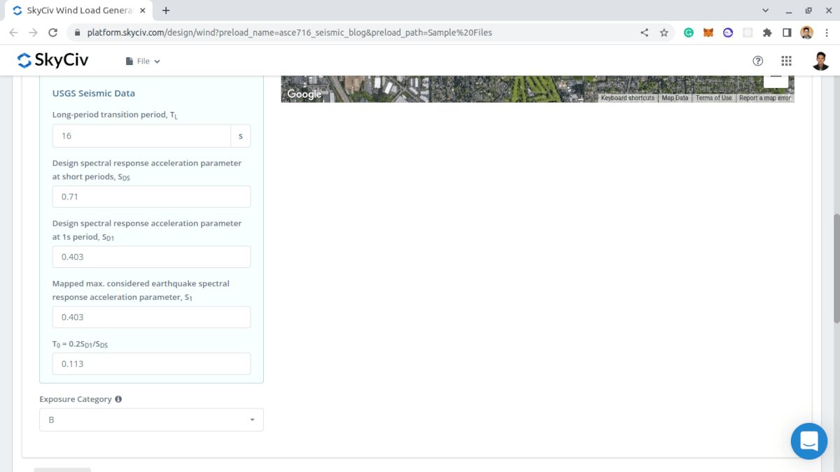
Φιγούρα 9. Αποτελέσματα από σεισμικά δεδομένα USGS.
Οι χρήστες μπορούν να τροποποιήσουν τις παραμέτρους που λαμβάνονται από τις υπηρεσίες Web USGS για να αποκτήσουν το καταλληλότερο σεισμικό φορτίο για την κατασκευή.
Δεδομένα δομής
Στην καρτέλα Structure Data, απλά πρέπει να ορίσετε τα τυπικά δεδομένα κτιρίου: Προφίλ στέγης, Μήκος Κτιρίου, Πλάτος κτιρίου, Μέσο ύψος στέγης, και Roof Pitch Angle.
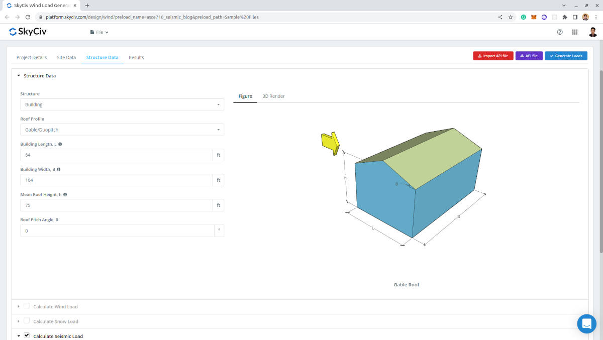
Φιγούρα 10. Εισαγωγή δεδομένων κτιρίου.
Σεισμικά Δεδομένα
Να προχωρήσουμε στους σεισμικούς υπολογισμούς, τα απαιτούμενα είναι τα εξής:
- Σύστημα δομής – για τον προσδιορισμό των τιμών του \({ντο}_{τ} \) και \(Χ \) που θα χρησιμοποιηθεί για τον υπολογισμό της κατά προσέγγιση θεμελιώδους περιόδου της κατασκευής \({Τ}_{ένα} \)
- Κατά προσέγγιση θεμελιώδης περίοδος της δομής \({Τ}_{ένα} \) – μπορεί να οριστεί από τον χρήστη για τον καταλληλότερο υπολογισμό του σεισμικού φορτίου
- Συντελεστής Τροποποίησης Απόκρισης \( Ρ \) – η προεπιλεγμένη τιμή είναι 8.5 και να τροποποιηθεί για πιο κατάλληλα σεισμικά αποτελέσματα
- Συντελεστής πλεονασμού, \( ρ \) – η προεπιλεγμένη τιμή είναι 1.0 και μπορεί να τροποποιηθεί. Χρησιμοποιείται στον υπολογισμό των δυνάμεων του διαφράγματος
- Βάρη δαπέδου – χρησιμοποιείται για την κατακόρυφη κατανομή της διάτμησης βάσης και για τις δυνάμεις του διαφράγματος. Απαιτούνται δεδομένα ανά επίπεδο: Επίπεδο (για χαρακτηρισμό), Ανύψωση, και Βάρος
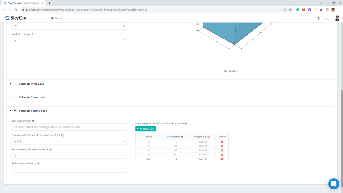
Φιγούρα 11. Σεισμικές παράμετροι που απαιτούνται για τον σεισμικό υπολογισμό.
Αποτελέσματα
Η έξοδος του υπολογισμού είναι οι σεισμικές παράμετροι που χρησιμοποιούνται και η υπολογισμένη σεισμική διάτμηση βάσης \(Β \), σεισμικές δυνάμεις ανά επίπεδο, και δυνάμεις διαφράγματος ανά επίπεδο.
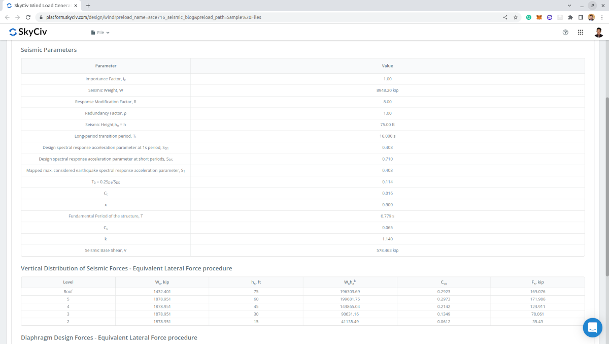
Φιγούρα 12. Παράμετροι εισόδου και αποτελέσματα για τον υπολογισμό του σεισμικού φορτίου.
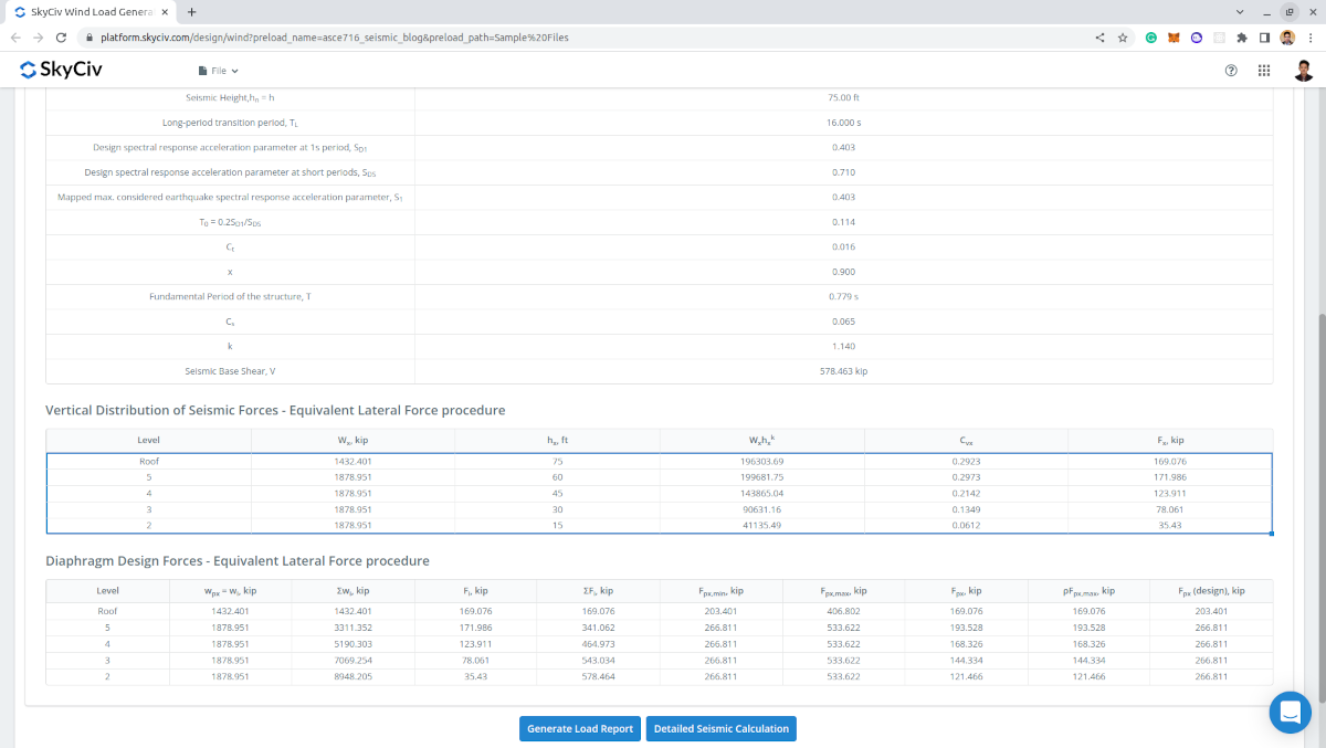
Φιγούρα 13. Πίνακες σεισμικών δυνάμεων ανά επίπεδο συμπεριλαμβανομένων των δυνάμεων σχεδιασμού του διαφράγματος.
Λεπτομερής έκθεση
Κατά τη δημιουργία των αποτελεσμάτων, Επαγγελματίες χρήστες λογαριασμών και εκείνοι που αγόρασαν το αυτόνομη μονάδα γεννήτριας φορτίου μπορεί να δημιουργήσει έναν λεπτομερή σεισμικό υπολογισμό. Η αναφορά εμφανίζει όλες τις παραμέτρους και τις υποθέσεις που χρησιμοποιούνται στον σεισμικό υπολογισμό για να είναι διαφανής στον χρήστη. Η παραγόμενη αναφορά για αυτό το παράδειγμα υπολογισμού μπορεί να προσπελαστεί μέσω αυτού Σύνδεσμος.
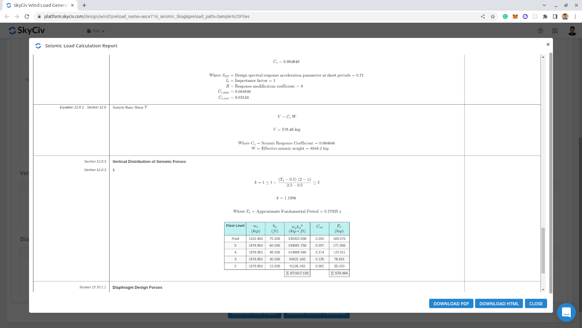
Φιγούρα 14. Λεπτομερής υπολογισμός σεισμικού φορτίου SkyCiv Load Generator.
Εκμεταλλευτείτε αυτή τη δυνατότητα με εγγραφή για έναν επαγγελματικό λογαριασμό ή με την αγορά του αυτόνομη μονάδα γεννήτριας φορτίου! Για υπάρχοντες χρήστες, ένα ΔΩΡΕΑΝ DEMO είναι επίσης διαθέσιμη εάν χρειάζεστε μια πιο ολοκληρωμένη λύση για τους υπολογισμούς φορτίου.
Για επιπλέον πόρους, μπορείτε να χρησιμοποιήσετε αυτούς τους συνδέσμους:

Δομικός μηχανικός, Ανάπτυξη προϊόντων
MS Πολιτικών Μηχανικών
βιβλιογραφικές αναφορές:
- Αμερικανική Εταιρεία Πολιτικών Μηχανικών. (2017, Ιούνιος). Ελάχιστα φορτία σχεδιασμού και συναφή κριτήρια για κτίρια και άλλες κατασκευές. Αμερικανική Εταιρεία Πολιτικών Μηχανικών.
- Charney, ΦΑ., Heausler, Τ., και ο Μάρσαλ, Ι. (2020). Σεισμικά φορτία: Οδηγός για τις διατάξεις του ASCE για το σεισμικό φορτίο 7-16. Αμερικανική Εταιρεία Πολιτικών Μηχανικών.
- = Απόσταση αντίθετα από τον άνεμο της κορυφής μέχρι όπου η διαφορά στο υψόμετρο του εδάφους είναι το μισό του ύψους του λόφου ή του λόφου