
Τι είναι μια σύνδεση διάτμησης?
Μια διατμητική σύνδεση είναι ένας σύνδεσμος που μεταφέρει τη δύναμη διάτμησης μεταξύ δύο μελών χωρίς να μεταφέρει σημαντική ροπή. Εάν μια δοκός φέρει εσωτερική δύναμη διάτμησης, ότι η δύναμη διέρχεται μέσω της σύνδεσης στη στήλη στήριξης ως αξονική δύναμη. Οι διατμητικές συνδέσεις συμπεριφέρονται ως καρφίτσα (FFFFFR στο SkyCiv Structural 3D), διαφορετικός στιγμιαίες συνδέσεις, που συγκρατούν την τελική περιστροφή.
Στην AISC 360-16 όροι αυτό είναι α απλός Η σύνδεση (Β3.4): Υποτίθεται ότι περιστρέφεται ελεύθερα και φέρει αμελητέα ροπή. ΟΠΩΣ ΚΑΙ 4100:2020 ονομάζει την ισοδύναμη διάταξη απλή κατασκευή. Μια ημιάκαμπτη άρθρωση είναι μια τρίτη περίπτωση, με πραγματική αλλά μερική περιστροφική ακαμψία, και πρέπει να διαμορφωθεί με αυτόν τον τρόπο αντί να αντιμετωπίζεται ως απλό.
Μια πλάκα ή γωνία μεταφέρει τη δύναμη μεταξύ των δύο μελών. Στο παραπάνω παράδειγμα, Οποιοδήποτε προς τα κάτω φορτίο στη δοκό διέρχεται στο μέλος στήριξης μέσω της γωνίας. Επειδή τίποτα δεν συγκρατεί τις φλάντζες της δοκού, η άρθρωση μπορεί να περιστραφεί, που είναι αυτό που το κάνει μια σύνδεση διάτμησης παρά μια σύνδεση ροπής.
Διατμητικές συνδέσεις είναι η πιο κοινή σύνδεση σε χαλύβδινο σκελετό. Όπου στηρίζεται ένα πλαίσιο, το στήριγμα παρέχει την πλευρική σταθερότητα, Έτσι, οι συνδέσεις στιγμής χρειάζονται μόνο όπου το πλαίσιο βασίζεται στη δράση του πλαισίου. Αυτός είναι ο λόγος για τον οποίο οι περισσότεροι σχεδιαστές επιδιώκουν μια διατμητική σύνδεση όπου το επιτρέπει η ανάλυση: είναι πιο απλά στην κατασκευή και φθηνότερα στην ανέγερσή τους.
Shear connection design comes down to following the beam reaction from the beam web, through the bolts, plate or angle and welds, into the support, and checking every part it passes through. This page sets out that procedure with the AISC 360-16 εξισώσεις, and links to five fully worked AISC calc sheet examples that apply it to real connections.
Το SkyCiv Connection Design ελέγχει τις διατμητικές συνδέσεις σε AISC 360-16 τόσο σε ASD όσο και σε LRFD, και να ΟΠΩΣ ΚΑΙ 4100:2020.
Τύποι συνδέσεων διάτμησης
Οι διατμητικές συνδέσεις ονομάζονται από το εξάρτημα που μεταφέρει το φορτίο και τη θέση του. Ποιες είναι διαθέσιμες εξαρτάται από τον κώδικα σχεδίασης και από το τι πλαισιώνει η δοκός, οπότε οι παρακάτω λίστες χωρίζονται με αυτόν τον τρόπο.
Δοκός σε διατομή I, ή δοκός σε δοκό (AISC 360-16)
Έξι διαμορφώσεις, κάθε διαθέσιμο πλαίσιο στη φλάντζα της στήλης, στον ιστό της στήλης, ή από δοκό σε δοκό μέσω του ιστού:
- Μονή γωνία. Ένα στήριγμα σε σχήμα L μεταξύ του ιστού της δοκού και του στηρίγματος. Η πιο ελαφριά επιλογή, και το πιο ευέλικτο, ώστε να ταιριάζει σε ελαφρά φορτία. The reaction sits off the support-side bolt line, so those bolts carry an eccentricity (worked example).
- Διπλή γωνία. Γωνίες και στις δύο όψεις του ιστού της δοκού. The extra angle puts the beam-side bolts in double shear and makes the connection more forgiving during erection, γι' αυτό είναι το άλογο εργασίας για βαρύτερα δοκάρια (worked example).
- Μονή πλάκα. Η γλωττίδα διάτμησης. Ένα πιάτο, συγκολλημένο στο στήριγμα και βιδωμένο στον ιστό της δοκού. Συνήθως το φθηνότερο της ομάδας, επειδή υπάρχει μία γραμμή συγκόλλησης και μία ομάδα μπουλονιών (worked example). When the plate has to reach past the column flanges into a column web, it becomes an extended single plate, which is designed differently (worked example).
- Διπλή πλάκα. Πλάκες και στις δύο όψεις του ιστού, χρησιμοποιείται όταν μια μεμονωμένη πλάκα δεν μπορεί να φέρει τη διάτμηση ή να χωρέσει στην απαιτούμενη ομάδα μπουλονιών.
- Τελική πλάκα. Μια πλάκα συγκολλημένη στο άκρο της δοκού και βιδωμένη στο στήριγμα. Χρειάζεται να κοπεί η δοκός στο μήκος με ακρίβεια, αφού η πλάκα δεν αφήνει καμία ρύθμιση (worked example).
- Άμεσα συγκολλημένος Ιστός. Ο ιστός της δοκού συγκολλήθηκε κατευθείαν στο στήριγμα, χωρίς ενδιάμεση πλάκα ή γωνία. Δεν υπάρχουν μπουλόνια για έλεγχο, αλλά χρειάζεται συγκόλληση πεδίου και εγκαταλείπει την ανοχή στύσης που παρέχει μια βιδωμένη λεπτομέρεια.
Δοκός σε στήλη HSS (AISC 360-16)
Το καδράρισμα σε κοίλο τμήμα αλλάζει αυτό που ταιριάζει, γιατί δεν υπάρχει φλάντζα για να βιδώσετε και δεν υπάρχει πρόσβαση στην μακρινή πλευρά για κλειδί. Διατίθενται πέντε διαμορφώσεις:
- Μονή γωνία και Διπλή γωνία
- Μονή πλάκα
- Ενιαίο WT. Ένα μπλουζάκι κομμένο από φαρδιά φλάντζα, Το στέλεχος του είναι συγκολλημένο ή βιδωμένο στον ιστό της δοκού και η φλάντζα του στην όψη του υποστυλώματος.
- Γωνία καθίσματος. Μια γωνία κάτω από την κάτω φλάντζα που φέρει τη δοκό στο ρουλεμάν, κανονικά με κορυφαίο κλιπ για σταθερότητα. Σε αντίθεση με τους τύπους που συνδέονται με το διαδίκτυο, αυτό λειτουργεί εκτός φλάντζας.
ΟΠΩΣ ΚΑΙ 4100:2020
Ο αυστραλιανός κώδικας καλύπτει το πλαίσιο από δοκό σε κολώνα και από δοκό σε δοκό, με τέσσερις διαμορφώσεις:
- Web Side Plate, το Α.Σ 4100 όνομα για την καρτέλα διάτμησης.
- Εύκαμπτη πλάκα άκρης
- Μονή γωνία και Διπλή γωνία
ΟΠΩΣ ΚΑΙ 4100 η κάλυψη είναι μόνο διάτμηση, και δεν επεκτείνεται σε στήλες HSS, καναλιών, στήριγμα ή συναρμογές. Αυτά είναι η AISC 360-16.
How to design a shear connection to AISC 360-16
Every shear connection is designed the same way: take the factored beam end reaction, [mathin] R_{u} [mathin] (ή [mathin] R_{a} [mathin] for ASD), and check each part of the load path against it. The reaction leaves the beam web, passes through the beam-side bolts or welds into the plate or angles, and then through the support-side bolts or welds into the column or girder. A failure anywhere along that path is a failure of the connection.
The equations below are the LRFD forms from AISC 360-16 και το Εγχειρίδιο AISC 15η Έκδοση. Για ASD, replace [mathin] \phi R_{n} [mathin] με [mathin] R_{n} / \Omega [mathin], SkyCiv Renderer API [mathin] \Omega [mathin] given in the same clause ([mathin] \Omega = 2.00 [mathin] όπου [mathin] \phi = 0.75 [mathin], και [mathin] \Omega = 1.50 [mathin] όπου [mathin] \phi = 1.00 [mathin]).
1. Λεπτομερή όρια (J3.3, J3.4)
Πριν από οποιονδήποτε έλεγχο αντοχής, the geometry has to be buildable and match the assumptions behind the strength equations. Bolts need a minimum spacing and edge distance, a wrench needs room to turn, and the plate or angle should be at least half the beam’s T dimension deep so the beam end stays stable. The minimum bolt spacing is:
[math] s_{min} = 2\tfrac{2}{3}\, d_{b} \qquad (3\, d_{b}\ \text{preferred}) [math]
Minimum edge distances come from Table J3.4, with an increment from Table J3.5 when the edge is measured across a slotted hole. In the worked examples a detailing limit is often the highest ratio in the whole connection. That is normal: designers lay the bolts out at the limits to keep the plate small.
2. Bolt shear and eccentricity (J3.6, Manual Part 7)
The strength of one bolt in shear is:
[math] \phi r_{v} = \phi\, F_{nv}\, A_{b}\, N_{s} = \phi\, F_{nv}\, \frac{\pi}{4} d_{b}^{2}\, N_{s}, \qquad \phi = 0.75 [math]
όπου [mathin] F_{nv} [mathin] comes from Table J3.2 (54 ksi for A325-N and 68 ksi for A490-N, grades within ASTM F3125) και [mathin] N_{s} [mathin] is the number of shear planes. The bolts in a double angle beam-side group are in double shear, [mathin] N_{s} = 2 [mathin].
The reaction rarely acts on the bolt line. When it sits a distance e away, the bolts carry a moment [mathin] R_{u}\, e [mathin] as well as the shear, and the group delivers fewer than n bolts’ worth of strength. Το στιγμιαίο κέντρο περιστροφής (ICOR) method finds that reduced count, the coefficient C, from the load-deformation curve of each bolt (Εγχειρίδιο εξ. 7-1):
[math] R = R_{ult} \left( 1 – e^{-10\Delta} \right)^{0.55} [math]
[math] \phi R_{n} = C\, \phi r_{v} [math]
How much eccentricity to design for depends on the connection type, and this is where the five worked examples differ most:
| Σύνδεση | Σχεδιαστική εκκεντρικότητα | Effect in the worked example |
|---|---|---|
| Μονό πιάτο (conventional) | [mathin] e = a/2 [mathin] from Manual Table 10-9 | 2 in to the bolt line becomes e = 1 σε; three bolts give C = 2.71 |
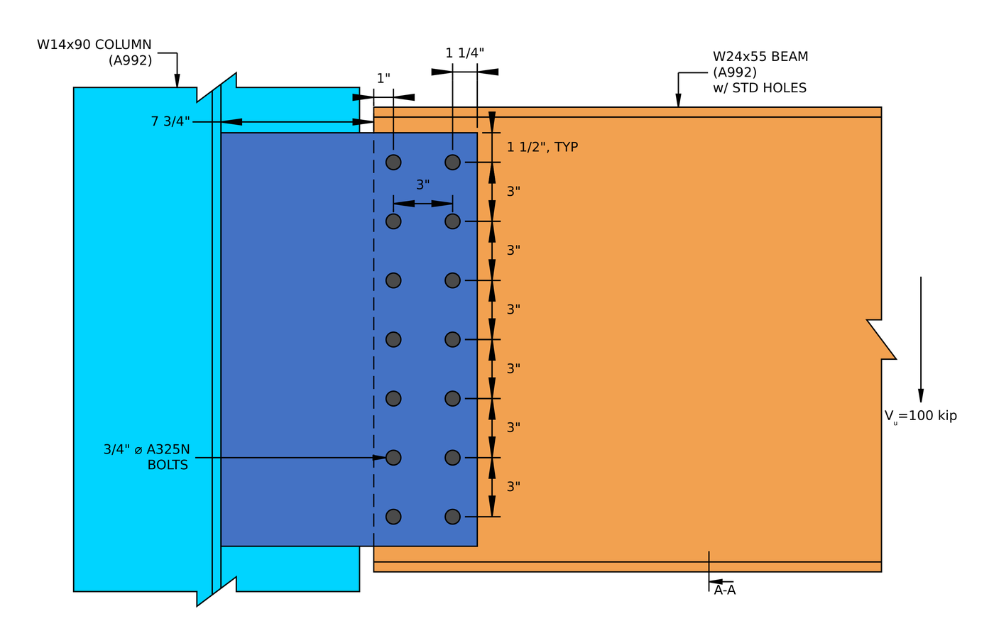
| Extended single plate | Full distance from the weld to the bolt group | ε = 10.25 in cuts 14 μπουλόνια σε 6.29 effective bolts |
| Single angle, support side | [mathin] e = g + t_{w}/2 [mathin], from the support bolt line to the middle of the beam web | ε = 1.85 in cuts 2 μπουλόνια σε 1.24 μπουλόνια’ worth |
| Διπλή γωνία, beam side | Neglected (Manual Part 10) | The bolt group is treated as concentric |
For the iteration itself, βλέπω Υπολογισμός ομάδας μπουλονιών με χρήση ICOR, or run a bolt group in the αριθμομηχανή μπουλονιών.
3. Ρουλεμάν μπουλονιών και σχίσιμο (J3.10)
Each bolt pushes on the edge of its hole. The ply either crushes locally around the hole (ρουλεμάν) or tears a strip out to the next hole or the edge (λυσσασμένο). With deformation at service load a design consideration:
[math] \phi r_{n} = \phi\, \min\left( 1.2\, l_{c}\, t\, F_{u},\ 2.4\, d_{b}\, t\, F_{u} \right), \qquad \phi = 0.75 [math]
[math] l_{c1} = L_{e} – \frac{d_{h}}{2} \qquad l_{c2} = s – d_{h} [math]
The edge bolt has the short clear distance [mathin] l_{c1} [mathin], so tear-out usually limits it, while the inner bolts reach the 2.4 d t Fεσύ bearing cap. Check every ply: the plate or angles, and the beam web. A thin beam web is often the weak ply, because the angles or plate are sized independently. In the double angle example the two 1/4 in angles give 0.5 in of steel against the bolts, αλλά το 1/4 in beam web has only one ply, and bearing on the web is the highest strength ratio, στο 0.760.
Each bolt then delivers the least of its shear, bearing and tear-out strengths, and the group strength is the sum (J3.6 Σχόλιο):
[math] \phi R_{n,eff} = \frac{C}{n} \sum_{i=1}^{n} \min\left( \phi r_{v},\ \phi r_{n,plate,i},\ \phi r_{n,web,i} \right) [math]
4. Διάτμηση μπλοκ (J4.3)
A block of the plate, angle or coped beam web can tear out around the bolt group: shear along the line of holes plus tension across to the free edge, usually an L-shaped block.
[math] \phi R_{n} = \phi \left( 0.6\, F_{u} A_{nv} + U_{bs} F_{u} A_{nt} \right) \le \phi \left( 0.6\, F_{y} A_{gv} + U_{bs} F_{u} A_{nt} \right), \qquad \phi = 0.75 [math]
[mathin] U_{bs} = 1 [mathin] when the tension stress is uniform, which is the case for a single line of bolts. The net areas deduct each hole at [mathin] d_{h} + 1/16\,in [mathin] for damage during punching (Β4.3). In the shear end plate example, block shear of the plate is the second highest ratio, στο 0.920.
5. Shear yielding and shear rupture (J4.2)
The plate or angles carry the whole reaction in shear, across the gross section (ενδοτικότητα) and across the net section through the holes (ρήξη):
[math] \phi R_{n} = \phi\, 0.6\, F_{y}\, A_{gv}, \qquad \phi = 1.00 [math]
[math] \phi R_{n} = \phi\, 0.6\, F_{u}\, A_{nv}, \qquad \phi = 0.75 [math]
In the single plate example, shear rupture of the 1/2 in plate is the highest load check, στο 0.629.
6. Plate flexure and the shear-flexure interaction
The reaction acts at a distance from the support, so a single plate is a short cantilever. SkyCiv checks it with the Manual’s double-coped beam procedure, which treats the plate like a beam web coped top and bottom, and checks flexural rupture on the net section through the holes. Because the same section carries shear and moment, the two combine:
[math] \left( \frac{V_{u}}{\phi V_{n}} \right)^{2} + \left( \frac{V_{u}}{\phi R_{n}} \right)^{2} \le 1.0 [math]
This check grows with the eccentricity. In the conventional shear tab it is minor, but in the extended single plate example the rupture interaction governs the connection at 0.938.
7. Εύπλαστο: the maximum plate thickness (Manual Part 10)
A shear connection is assumed to rotate. If the plate is stronger in bending than the bolts are in shear, the bolts break before the plate yields, which is a brittle failure and contradicts the simple connection assumption. The Manual caps the plate thickness so the plate yields first:
[math] M_{max} = \frac{F_{nv}}{0.90}\, \frac{\pi}{4} d_{b}^{2}\, C’ [math]
[math] t_{max} = \frac{6\, M_{max}}{F_{y}\, d_{p}^{2}} [math]
ντο’ is the bolt group coefficient for moment alone. This is the one check that a thicker plate makes worse. In the single plate example a 1/2 in plate sits at 0.966 of its limit.
8. Weld strength and the base metal limit (J2.4, Manual Part 9)
The fillet welds that join the plate or angles to the support (or the end plate to the beam web) carry the reaction along their length:
[math] \phi R_{n} = \phi\, 0.6\, F_{EXX}\, \frac{\sqrt{2}}{2}\, w\, L_{w} \left( 1 + 0.5\, \sin^{1.5}\theta \right), \qquad \phi = 0.75 [math]
For a vertical reaction on vertical welds, [mathin] \theta = 0 [mathin] and the directional factor is 1.0. The steel either side of the weld also limits how much of the weld size counts. For welds on both faces of a plate of thickness t, the usable size in sixteenths is:
[math] D_{max} = \frac{ \frac{t}{2}\, F_{u} }{3.09\,kip/in} [math]
So a bigger weld does not always help. In the shear end plate example the 0.355 in beam web limits the usable weld to about 0.233 σε, and the weld governs the connection at 0.995. For a single plate, the Manual also asks for fillets of [mathin] \frac{5}{8}\, t_{p} [mathin] και στις δύο πλευρές, so that the weld can develop the plate if it yields. Try sizes in the αριθμομηχανή συγκόλλησης.
9. The supporting and supported members
The connection is only as good as the steel it attaches to. A coped beam has a reduced section at the cope, which needs its own block shear, shear and flexure checks; the single angle example works these through for a W12x14 coped at the top flange. Where the beam frames into a girder web or a thin column web, check bearing and tear-out on that web too.
Shear connection design examples (AISC 360-16 LRFD)
Each example below is a full AISC calc sheet from SkyCiv Connection Design, written out step by step with every equation, substituted value and DCR. They show how the governing check moves from one connection type to the next.
| Παράδειγμα | Members and load | Σύνδεση | Governing load check |
|---|---|---|---|
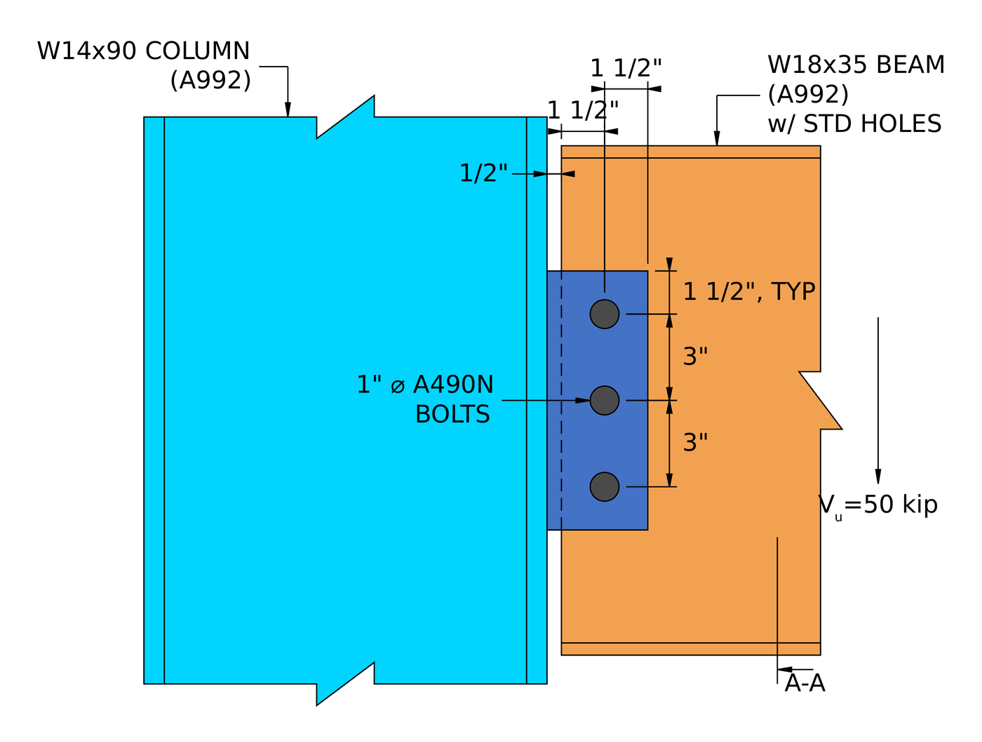
| Μονό πιάτο (γλωττίδα διάτμησης) | W18x35 beam to W14x90 column flange, 50 δέρμα μόσχου ακατέργαστου | 1/2 σε πιάτο, three 1 in A490-N bolts | Plate shear rupture, 0.629 |
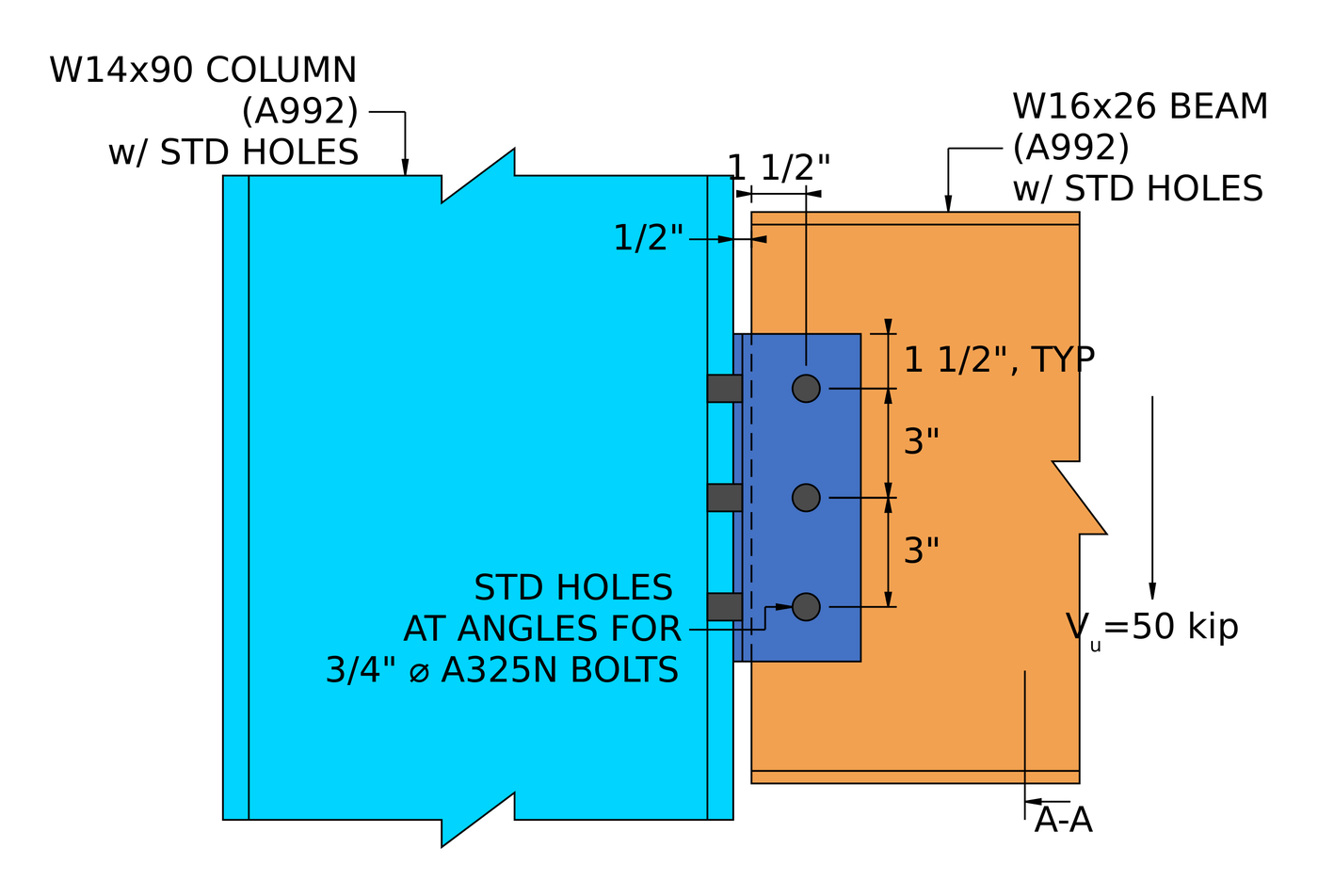
| Διπλή γωνία | W16x26 beam to W14x90 column flange, 50 δέρμα μόσχου ακατέργαστου | 2L4x3-1/2×1/4, three rows of 3/4 in A325-N each side | Bolt bearing on the beam web, 0.760 |
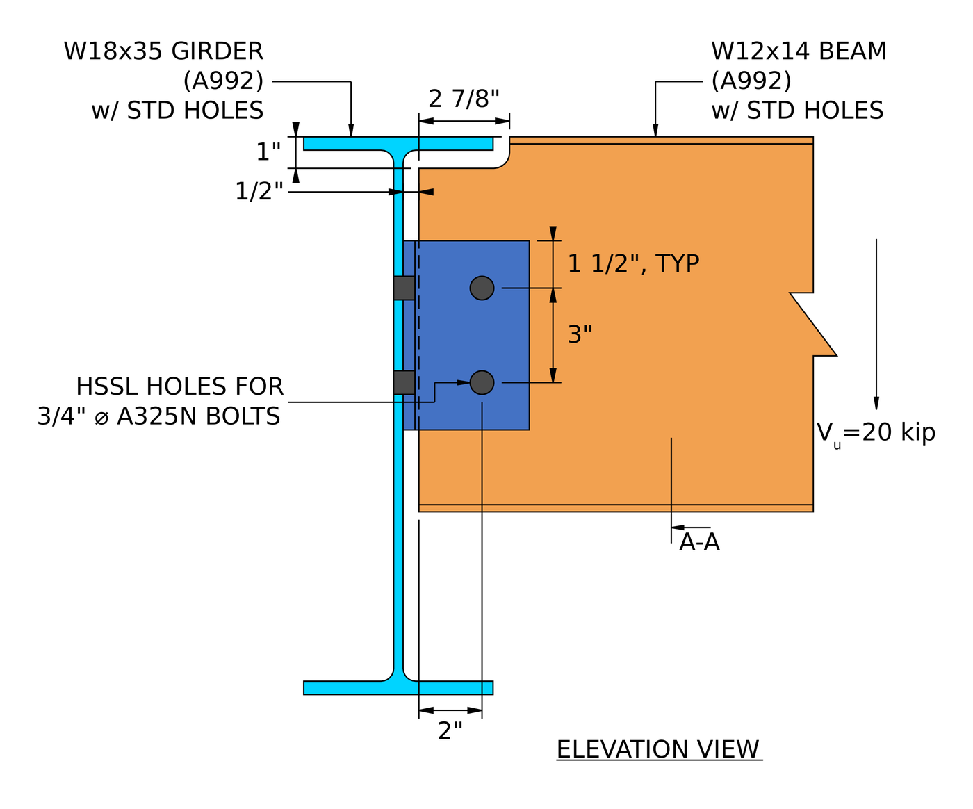
| Single angle | Coped W12x14 beam to W18x35 girder web, 20 δέρμα μόσχου ακατέργαστου | L4x3x3/8, two rows of 3/4 in A325-N each leg | Bolt shear at the girder, 0.901 |
| Extended single plate | W24x55 beam to W14x90 column web, 100 δέρμα μόσχου ακατέργαστου | 3/8 Χ 13 Χ 21 σε πινακίδα Α36, δεκατέσσερα 3/4 στο Α325-Ν | Αλληλεπίδραση διάτμησης και κάμψης (ρήξη), 0.938 |
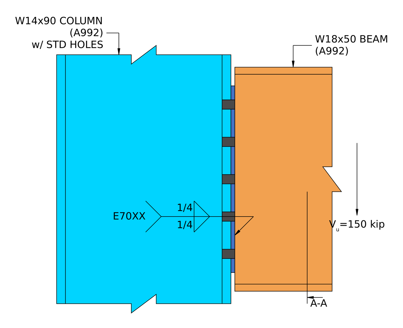
| Shear end plate | W18x50 beam to W14x90 column flange, 150 δέρμα μόσχου ακατέργαστου | 5/16 Χ 8 1/2 Χ 15 σε πινακίδα Α36, ten 3/4 στο Α325-Ν, 1/4 in fillets | Weld at the beam web, 0.995 |
The pattern is worth knowing. A short, conventional shear tab is rarely close to its limit. Once the reaction moves away from the bolts, as in the single angle and the extended plate, the eccentricity drives the design. And in a welded connection like the end plate, the thinnest piece of base metal decides the weld.
For the theory behind all five, βλέπω design of steel connections using AISC 360-16.
Which shear connection should you use?
| Σύνδεση | Best for | Watch for |
|---|---|---|
| Μονό πιάτο (γλωττίδα διάτμησης) | Most beam-to-column and beam-to-girder framing. One shop weld, one field bolt group | Ελκιμότητα της πλάκας (τΜέγιστη), and the Table 10-9 limits on the conventional configuration |
| Extended single plate | Framing into a column web between the flanges, without coping the beam | Full eccentricity, plate flexure and the shear-flexure interaction |
| Διπλή γωνία | Heavier reactions, and erection where the beam needs to be dropped in between supports | Bearing on a thin beam web, and two bolt groups to detail |
| Single angle | Light reactions, and access from one side only | Eccentricity at the support bolts, which cuts the group strength |
| Shear end plate | Shop-welded beams with fast, all-bolted field erection | Accurate beam length, and the weld limited by the beam web thickness |
Τι ελέγχει το λογισμικό?
Για διατμητική σύνδεση, ο σχεδιασμός εκτελεί τόσο ένα πέρασμα λεπτομερειών όσο και ένα πάσο αντοχής.
Η λεπτομέρεια τρέχει πρώτα και πιάνει τη γεωμετρία: αποστάσεις άκρων μπουλονιών, απόσταση μπουλονιών (γήπεδο και μετρητής), κενά εργαλείων, και ελάχιστες και μέγιστες διαστάσεις πλάκας, συν ανίχνευση συγκρούσεων μεταξύ πλακών, μπουλόνια και συγκολλήσεις. Μια σύνδεση που αποτυγχάνει εδώ δεν φτάνει ποτέ στη λύση. Αυτό είναι συνήθως αυτό που θέλετε, γιατί οι αριθμοί δεν έχουν σημασία αν η λεπτομέρεια δεν μπορεί να κατασκευαστεί.
The strength checks then cover every limit state in the procedure above: bolt shear by ICOR, ρουλεμάν μπουλονιών και σχίσιμο, ρήξη διάτμησης μπλοκ, διατμητική υποχώρηση και ρήξη, plate flexure and its interaction with shear, εύπλαστο, and weld strength with the base metal limit, plus the checks on coped beams and the supporting member. The calculation report shows every formula, πλήρης έλεγχος σχεδιασμού και αναφορά κώδικα, με τους αριθμούς ρήτρας από την AISC 360-16 ή AS 4100:2020, ώστε να μπορείτε να ακολουθήσετε τον υπολογισμό αντί να τον αναλάβετε με εμπιστοσύνη. The worked examples above are written from those reports.
Για την πλευρά του συνδετήρα αυτού, δείτε την τεκμηρίωση μπουλόνια και συγκολλήσεις.
Ποια είναι η διαφορά μεταξύ σύνδεσης Shear και Moment?
Μια διατμητική σύνδεση μεταφέρει μόνο διάτμηση. Μια στιγμιαία σύνδεση μεταφέρει επίσης κάμψη. Σκεφτείτε το ως α μεντεσές: μια διατμητική σύνδεση επιτρέπει στο άκρο της δοκού να περιστρέφεται, μια στιγμή σύνδεση το κρατά.
Η διάκριση είναι μια απόφαση σχετικά με το μοντέλο ανάλυσης, όχι μόνο για τη λεπτομέρεια. Μια γλωττίδα διάτμησης σχεδιασμένη ως απλή πρέπει να είναι αρκετά εύκαμπτη ώστε να περιστρέφεται πραγματικά, which is what the ductility check enforces, και μια σύνδεση ροπών πρέπει να είναι αρκετά άκαμπτη ώστε να δικαιολογεί τη σταθερότητα που υπέθεσε το μοντέλο πλαισίου.
| Σύνδεση διάτμησης | Σύνδεση στιγμής | |
|---|---|---|
| Μεταφορές δυνάμεων | Μόνο διάτμηση | Διάτμηση και στιγμή |
| Εναλλακτικά ονόματα | Καρφιτσώθηκε, Μεντεσές, Απλός | Ακαμπτος, Σταθερός, Στιγμιαία αντίσταση |
| AISC 360-16 όρος | Απλή σύνδεση | Σύνδεση στιγμής FR ή PR |
| Περιστροφή | Επιτρέπει την περιστροφή | Περιορίζει την περιστροφή |
| Κωδικός Fixity λογισμικού | FFFFFR | FFFFFF |
Συχνές ερωτήσεις
How do you calculate the capacity of a shear connection?
Work out the strength of every limit state along the load path (bolt shear with the eccentricity, bearing and tear-out on each ply, διάτμηση μπλοκ, διατμητική υποχώρηση και ρήξη, κάμψη πλάκας, ductility and the welds) and take the lowest. That lowest value is the connection capacity, and the check that gives it is the governing limit state.
Is a shear connection the same as a pinned connection?
Ναί, for analysis. A shear connection is modelled as a pin, free to rotate and carrying no moment. In practice it does carry a small moment, γι' αυτό η AISC 360-16 B3.4 asks that a simple connection have enough rotation capacity to accommodate the beam end rotation. The ductility limit on plate thickness is one way the design makes sure of that.
What is the eccentricity in a shear tab, and why is it a/2?
Εγχειρίδιο AISC Πίνακας 10-9 sets the design eccentricity for a conventional single plate connection. For many bolt counts and hole types it is half the distance from the weld line to the bolt line, a/2, because the point of zero moment sits between the weld and the bolts. Outside the conventional limits, such as a plate extended into a column web, the full distance is used and the bolt group loses much more strength.
Which check usually governs a shear connection?
It depends on the type. In the five worked examples the governing load check was plate shear rupture (ενιαίο πιάτο), bearing on the beam web (διπλή γωνία), bolt shear with eccentricity (μονή γωνία), the shear-flexure interaction (extended single plate) and the weld (shear end plate). Thin beam webs and eccentricity are the two things to look at first.
Should the bolts be bearing type or slip-critical?
Most shear connections use snug-tight bearing-type bolts (A325-N, A490-N), which is what all five worked examples use. Slip-critical bolts are needed where slip would be a problem, such as oversized or slotted holes parallel to the load, or joints subject to fatigue or load reversal.
Can I design a shear connection with ASD instead of LRFD?
Ναί. The limit states are identical. Replace [mathin] \phi R_{n} [mathin] με [mathin] R_{n} / \Omega [mathin] and compare against the ASD reaction. SkyCiv Connection Design runs both, and switching between them is one setting.
Do the examples follow the AISC 15th or 16th edition Manual?
They follow AISC 360-16 και το Εγχειρίδιο AISC 15η Έκδοση, που είναι γραμμένο γύρω από αυτήν την Προδιαγραφή. The 16th Edition Manual pairs with AISC 360-22. The shear connection limit states are much the same, but clause and table references move, Επομένως, ελέγξτε τα σε σχέση με την έκδοση που χρησιμοποιεί το έργο σας.
Λογισμικό σχεδιασμού σύνδεσης SkyCiv
Τα μοντέλα και οι έλεγχοι παραπάνω είναι από Σχεδιασμός σύνδεσης SkyCiv. Καλύπτει 80+ προδιαμορφωμένους τύπους σύνδεσης, σχέδια στην AISC 360-16 (LRFD & ASD) και ως 4100:2020, και δείχνει κάθε τύπο, πλήρης έλεγχος σχεδιασμού και αναφορά κώδικα.
Μπορείτε να μοντελοποιήσετε τη σύνδεση σε 3D, ανταλλάξτε μπουλόνια, συγκολλήσεις ή πλάκες χωρίς να χάσετε τα δεδομένα φορτίου σας, δημιουργήστε φύλλα σχεδίασης 2D λεπτομερειών στο CloudCAD, και εξάγετε την τρισδιάστατη γεωμετρία στο IFC για συντονισμό στο Revit, Tekla ή Navisworks.
Εκτελείται εξ ολοκλήρου στο πρόγραμμα περιήγησης, χωρίς λήψεις, ενημερώσεις ή ρύθμιση IT.
The full module adds the step-by-step calculation report, like the worked examples above, with every capacity and DCR.
βιβλιογραφικές αναφορές
- AISC 360-16, Προδιαγραφές για δομικά κτίρια από χάλυβα: Β3.4, Β4.3, J2.4 (Εξ. J2-4), J3.2 (Πίνακας J3.2), J3.3, J3.4 (Πίνακας J3.4), J3.5 (Πίνακας J3.5), J3.6 (Εξ. J3-1) και Σχολιασμός, J3.10 (Εξ. J3-6a, J3-6c), J4.2 (Εξ. J4-3, J4-4), J4.3 (Εξ. J4-5).
- Εγχειρίδιο AISC Steel Construction, 15ου Έκδοση: Μέρος 7 (Εξ. 7-1, instantaneous center of rotation); Μέρος 9 (base metal limit on weld size, coped beam flexure); Μέρος 10 (simple shear connections, Τραπέζι 10-9, Εξ. 10-3 και 10-4).
- ΟΠΩΣ ΚΑΙ 4100:2020, Μεταλλικές Κατασκευές.

Χάρολντ Μουνάλεμ
Υπεύθυνος προϊόντων, Σχεδιασμός σύνδεσης
10+ χρόνια στο σχεδιασμό σύνδεσης χάλυβα
LinkedIn
