Πώς να μοντελοποιήσετε στοιβαγμένες δοκούς χρησιμοποιώντας Άκαμπτους συνδέσμους
Απλώς καθορίστε το μέλος “Τύπος” όπως και “Άκαμπτος σύνδεσμος” για να δημιουργήσετε ένα μέλος που λειτουργεί ως άκαμπτος σύνδεσμος. Όταν γίνει αυτό θα δείτε ότι ο άκαμπτος σύνδεσμος σχεδιάζεται με ανοιχτό γκρι χρώμα και έχει ένα “Ρ” σύμβολο δίπλα του:

Οι άκαμπτοι σύνδεσμοι μπορούν να είναι χρήσιμοι για τον καθορισμό άκαμπτων συνδέσεων μεταξύ δομών που περιλαμβάνουν στοιβαγμένες δοκούς ή μέλη. Συχνά θεωρούνται ως φανταστικοί δύσκαμπτοι σύνδεσμοι που ενώνουν τα μέλη ώστε να μπορούν να μεταφράζουν και/ή να περιστρέφονται μαζί. Ένας άκαμπτος σύνδεσμος μπορεί επίσης να χρησιμοποιηθεί για τον χειροκίνητο έλεγχο για τις αντισταθμίσεις μελών. Επιπροσθέτως, μπορείτε να αλλάξετε την σταθερότητα / απελευθερώσεις στον άκαμπτο σύνδεσμο για να ελέγξετε ποιες δυνάμεις και επιπτώσεις έχει σε αυτό που συνδέεται.
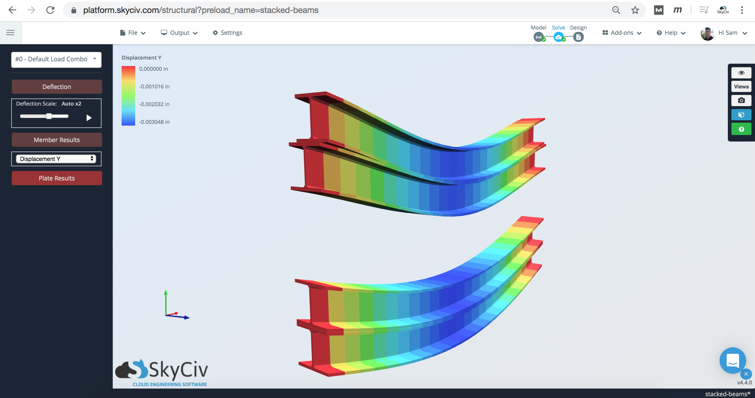
Βλέποντας τα αποτελέσματα της ανάλυσης, μπορείτε να το δείτε καθώς η επάνω δοκός είναι φορτωμένη, και εκτρέπεται, το ίδιο και η δοκός από κάτω:
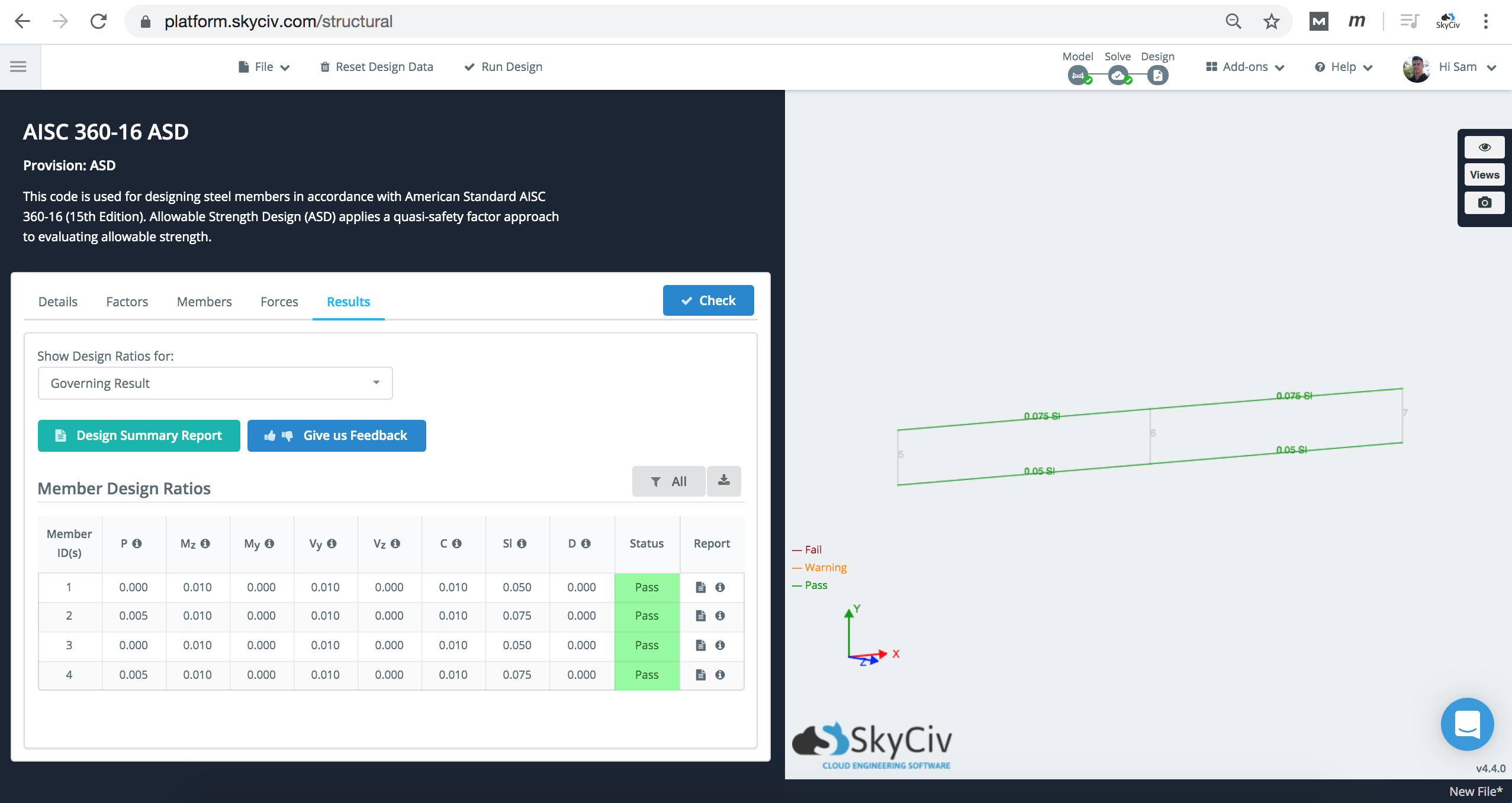
Οι έλεγχοι σχεδιασμού μελών θα συνεχίσουν να εκτελούνται, ωστόσο, Είναι σημαντικό να λάβετε υπόψη τους περιορισμούς του λογισμικού για την κατανόηση των μη στερεωμένων μηκών και των σταθεροποιήσεων των άκρων των μελών. Σε αυτό το σενάριο, το Lb θα πρέπει να προσαρμόζεται σύμφωνα με τις σχεδιαστικές σας ανάγκες.
Μέθοδος 2: Χρήση προσαρμοσμένων σχημάτων στο Section Builder
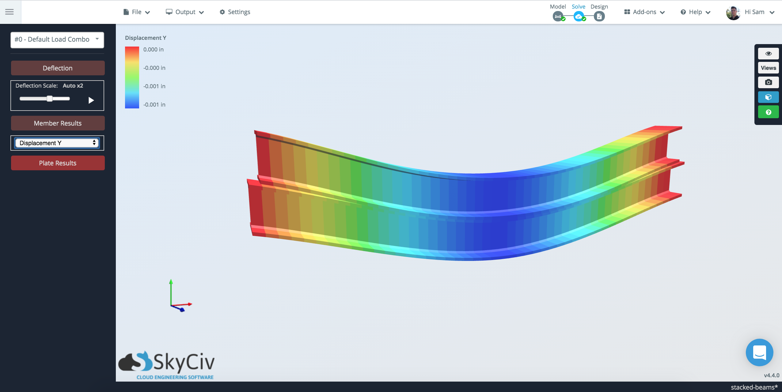
Μια εναλλακτική μέθοδος στα παραπάνω είναι η χρήση του SkyCiv Section Builder για τη μοντελοποίηση δύο μοντέλων το ένα πάνω στο άλλο, και αντιμετωπίζοντάς το ως ένα στοιχείο:
Αυτό θα χρησιμοποιήσει το FEA για να υπολογίσει τις γεωμετρικές ιδιότητες αυτού του «ενός».’ Ενότητα. Στη συνέχεια θα χρησιμοποιήσει αυτές τις γεωμετρικές ιδιότητες μαζί με ολόκληρο το στοιχείο γραμμής. Μπορείτε να δείτε περισσότερα σχετικά με αυτήν τη μέθοδο στην ακόλουθη σελίδα τεκμηρίωσης: Σύνθετα και χτισμένα σχήματα στο SkyCiv
Σύγκριση αποτελεσμάτων
Κατά τη μοντελοποίηση των δύο μεθόδων μαζί, τα αποτελέσματα είναι αρκετά συνεπή για την εκτροπή:
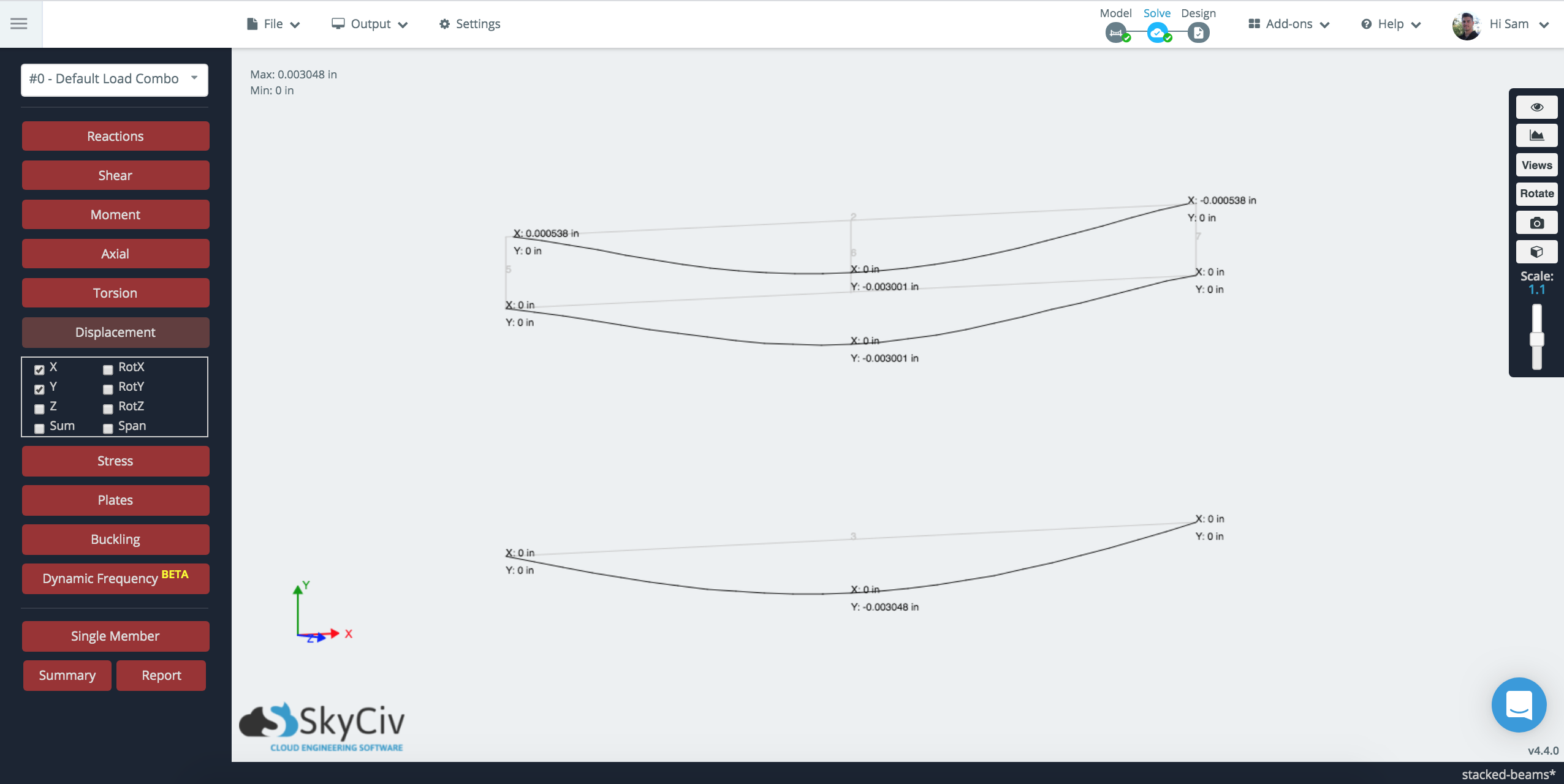
Δεδομένου ότι τα μέλη συνδέονται μόνο σε ορισμένα σημεία κατά μήκος της δοκού, υπάρχει διακύμανση στη συνδεσιμότητα των δοκών. Στον πάτο (Μέθοδος δημιουργίας ενότητας), το στοιχείο αντιμετωπίζεται ως ένα κομμάτι, ενώ στη μέθοδο Rigid Link, συνδέεται μόνο στο 3 σημεία κατά μήκος του ανοίγματος της δοκού.