
SkyCiv Foundation Design Module combines an intuitive interface with powerful analysis capabilities, making it easy to model, αναλύει, and design isolated foundations (γνωστά και ως βάσεις pad). As of version 4.0.0, the Isolated Foundation module features a top menu with seven tabs: Λεπτομέριες, Γεωμετρία, Υλικά, Εδαφος, Ενίσχυση, Φορτία, and Results, paired with a two-panel workspace below.
Κορυφαίο μενού: Navigating Your Model
Switching between tabs lets you move through each stage of your foundation model without losing your place.
- Λεπτομέριες, Γεωμετρία, Υλικά, Εδαφος, Ενίσχυση, Φορτία: Define every aspect of the isolated foundation, from basic project details to soil properties and applied loads.
- Αποτελέσματα: Run design checks directly from this tab, then review summary results or open the detailed report for a full breakdown of calculations and code checks.
Left Panel: Input Fields
The left panel displays the input fields relevant to whichever tab is currently active, keeping the workspace focused and uncluttered while building the model.
Right Panel: 3D Renderer and Results
The right panel shows a live 3D renderer that updates as the model is built. After running design checks, this panel also displays the FEA (Ανάλυση πεπερασμένων στοιχείων) Αποτελέσματα, visualizing how the isolated foundation performs under load.
Selecting an Isolated Footing
Launching SkyCiv Foundation opens a design code launcher modal automatically. This modal is used to select the design code, εκδοχή, and unit system (Αυτοκρατορικό ή Μετρικό), followed by clicking the Pad Footing card to start a new isolated footing model.
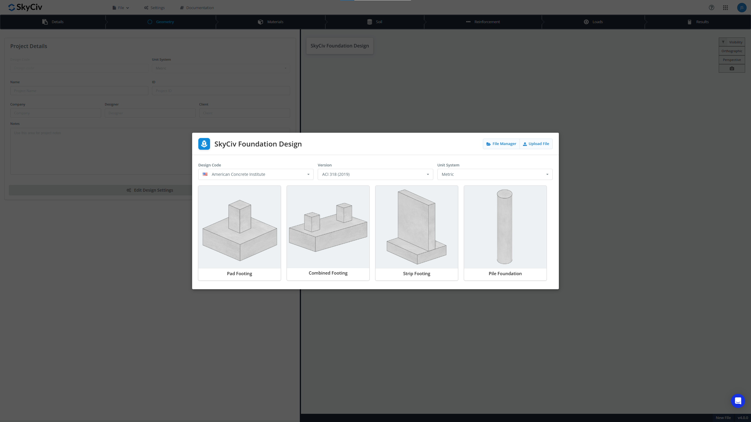
Isolated footing (pad footing) design is currently available for the following design codes:
- American standard: ACI 318 (2014 και 2019)
- Αυστραλιανό πρότυπο: ΟΠΩΣ ΚΑΙ 3600 (2009 και 2018)
- Καναδικό πρότυπο: CSA A23.3 (2014)
- European standard: Eurocode EN2, EN7 (2004)
Existing models can also be opened by loading a file through the file manager or by uploading a JSON object.
Λεπτομέρειες Έργου
The Details tab displays general information about the model and project, and allows this information to be viewed and edited. Available project details include Name, ταυτότητα, Εταιρία, Σχεδιαστής, Πελάτης, and additional Notes about the project.
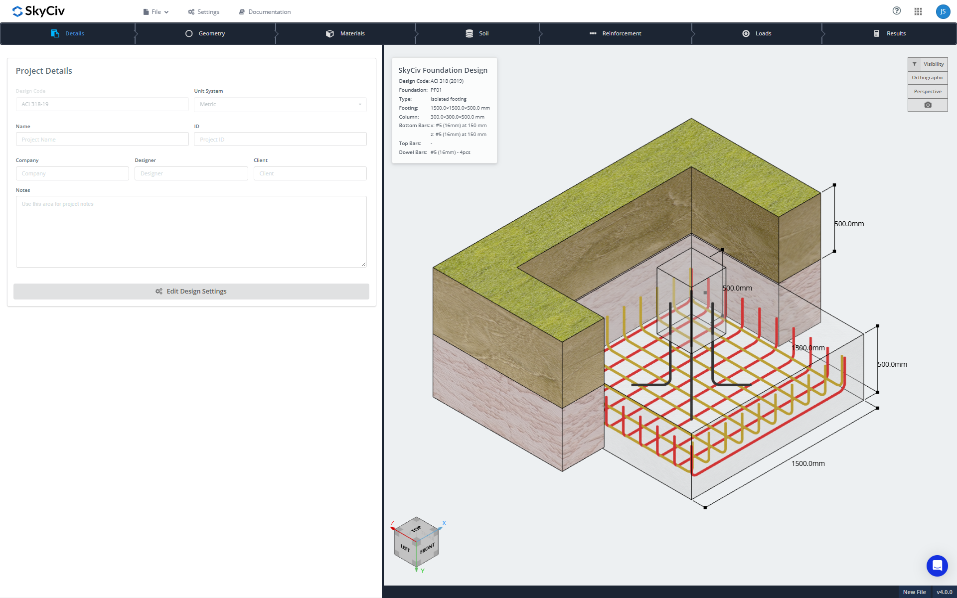
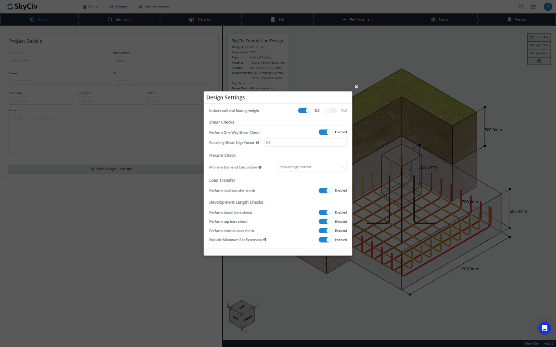
Design settings can also be accessed from this tab by clicking the Edit Design Settings button, or from the shortcut available on the top menu. Design settings contain the design and calculation options used to run the model.
Γεωμετρία
The Geometry tab contains all input fields needed to define footing and column dimensions, column shape, and offset in the X and Z directions. Column shape can be set to either rectangular or round. Offset refers to the center-to-center distance between the column and the footing along the X and Z axes.
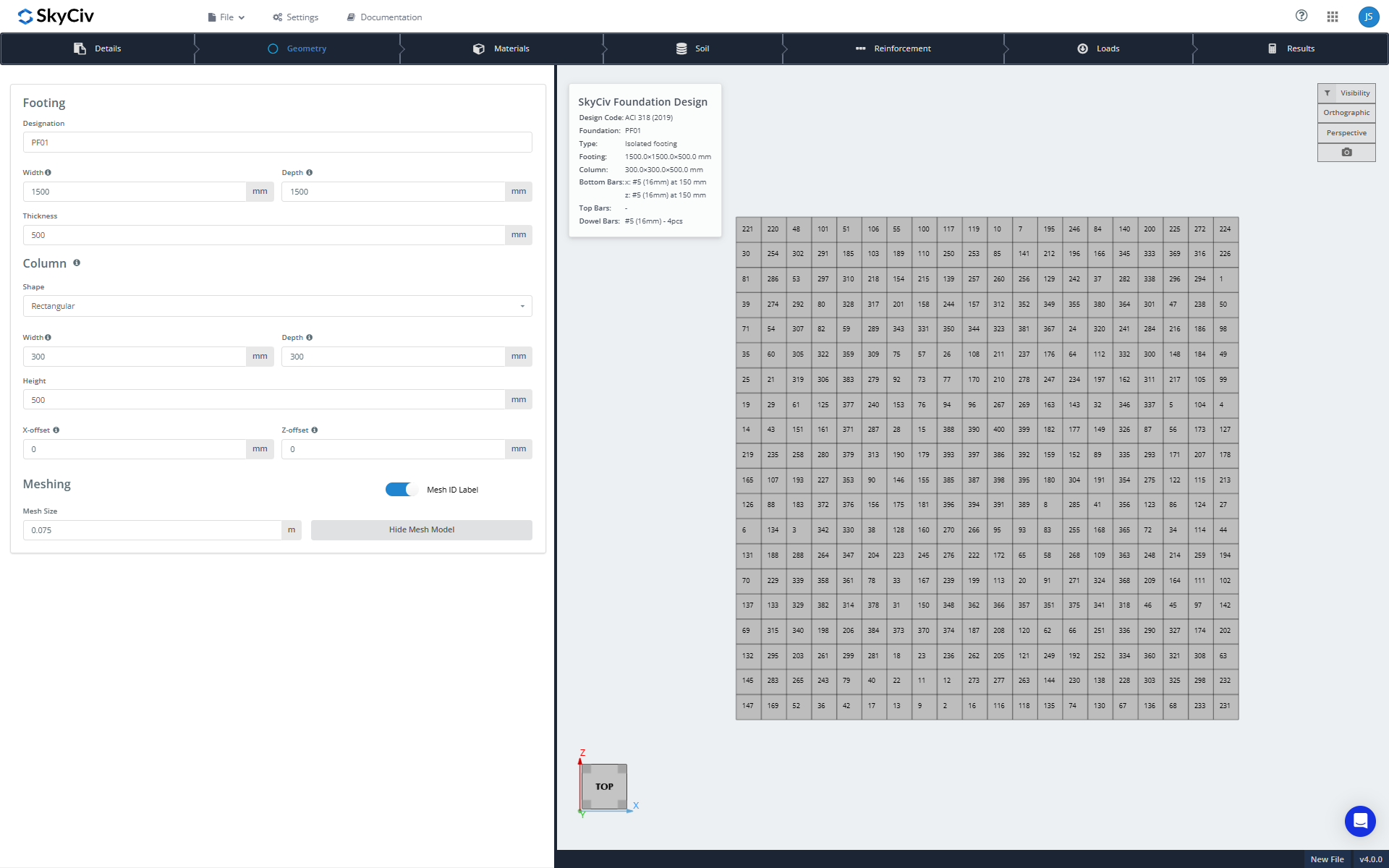
This tab also includes meshing options, where mesh size can be adjusted and previewed directly on the model in the 3D renderer.
Υλικά
The Materials tab contains all input fields for concrete and reinforcing steel properties.
Concrete properties include:
- Αντοχή σκυροδέματος
- η δύναμη τριβής που θα αποτρέψει την ολίσθηση του τοίχου είναι το συνολικό κατακόρυφο φορτίο πολλαπλασιαζόμενο με τον συντελεστή τριβής εδάφους-σκυροδέματος που ορίζεται για το εδαφικό υλικό υποδομής και η δύναμη ολίσθησης είναι το αποτέλεσμα της πλευρικής πίεσης του εδάφους που διατηρείται και της πίεσης που σχετίζεται με την παρουσία επιβάρυνσης
- Elasticity modulus
- αναλογία Poisson
Steel properties include:
- Yield strength
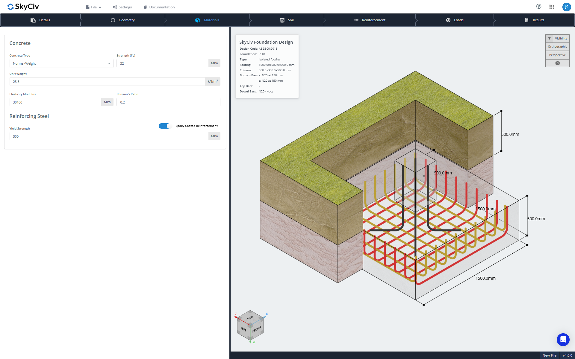
Additional input fields appear based on the requirements of the selected design code, such as the concrete modification factor, or toggles for whether the steel reinforcement is epoxy-coated or uses welded transverse reinforcement.
Εδαφος
The Soil tab contains input for soil and other geotechnical properties, including unit weight, soil thickness, συνοχή, γωνία τριβής, and coefficient of friction. These properties are primarily used for bearing capacity and stability checks.
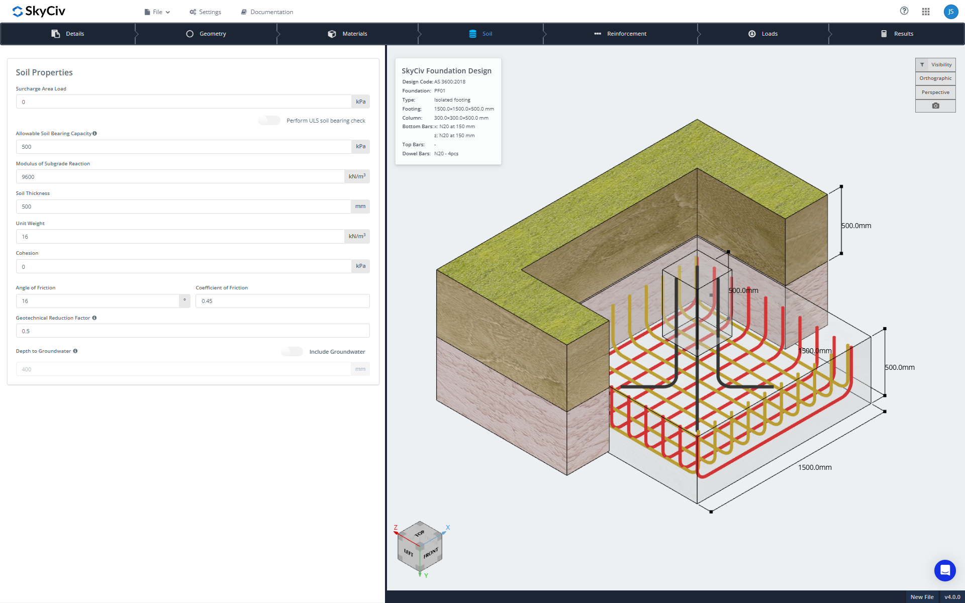
This tab also includes:
- Επιπρόσθετο φορτίο: Additional load applied over the soil surface area.
- Allowable bearing capacity: Used for the soil bearing capacity check.
- Modulus of subgrade reaction: A geotechnical parameter that relates soil pressure to deflection, used to model the soil as a bed of springs in the FEA. This value automatically updates when the Gross Allowable Soil Bearing Capacity is changed, though it can still be overwritten manually.
- Groundwater: An option to include groundwater conditions when present at the site.
Ενίσχυση
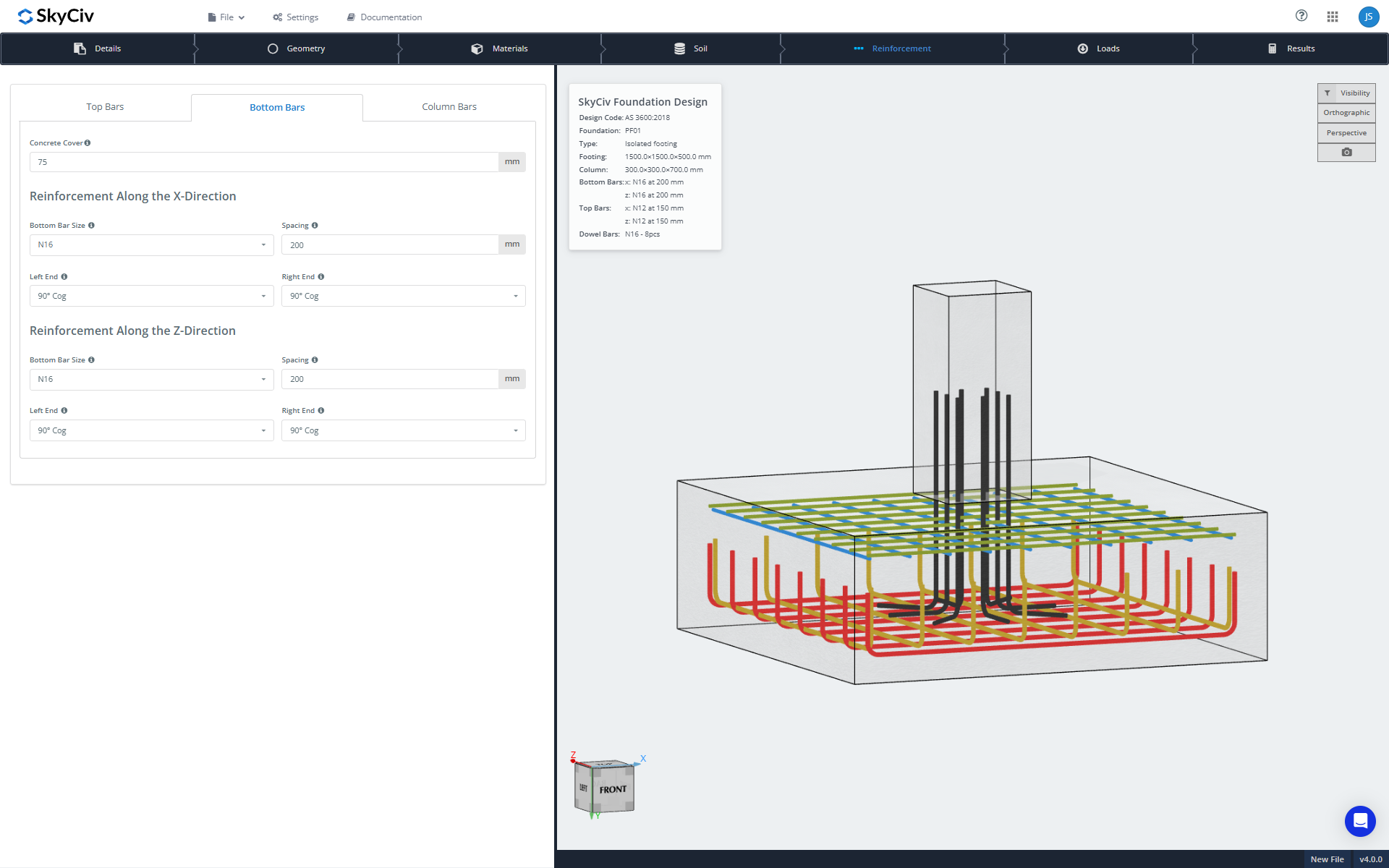
The Reinforcement tab contains all input for steel reinforcement layout, covering bottom bars, top bars, and column dowel bars. Each bar type has its own dedicated sub-tab.
Bottom and Top Bars
Input options include concrete cover value, bar size and spacing, and left and right bar configurations (straight bar, 90-degree hook, or 180-degree hook). The top bars sub-tab includes an additional option to add or remove top bars.
Column Dowel Bars
Dowel bars, the steel bars placed between the column and the footing, include layout options for bar size and number.
Φορτία
The Loads tab contains a Load Cases sub-tab with a table for entering loads applied to the column, including axial loads, φορτία διάτμησης, και στιγμές. The loads displayed on the 3D renderer can also be changed here, based on the selected load combination for the design code in use.
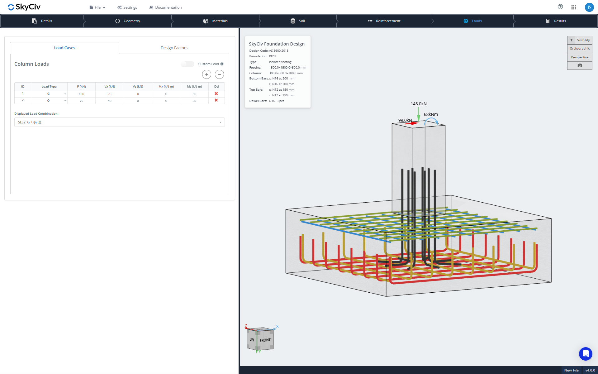
A Custom Loads toggle is also available for cases where factored loads need to be entered directly.
The Design Factors sub-tab is accessible from here as well, containing all load factors and other design factors required for the design, based on the requirements of the selected design code.
Αποτελέσματα
Accessing the Results tab automatically triggers the design checks to run. If any input is changed afterward, the tab prompts for the design checks to be re-run to keep results up to date.
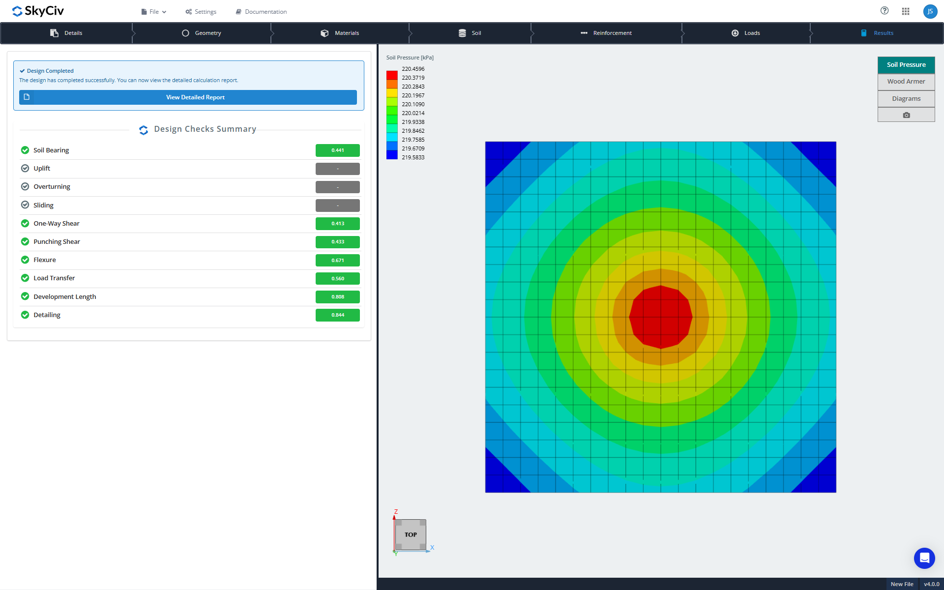
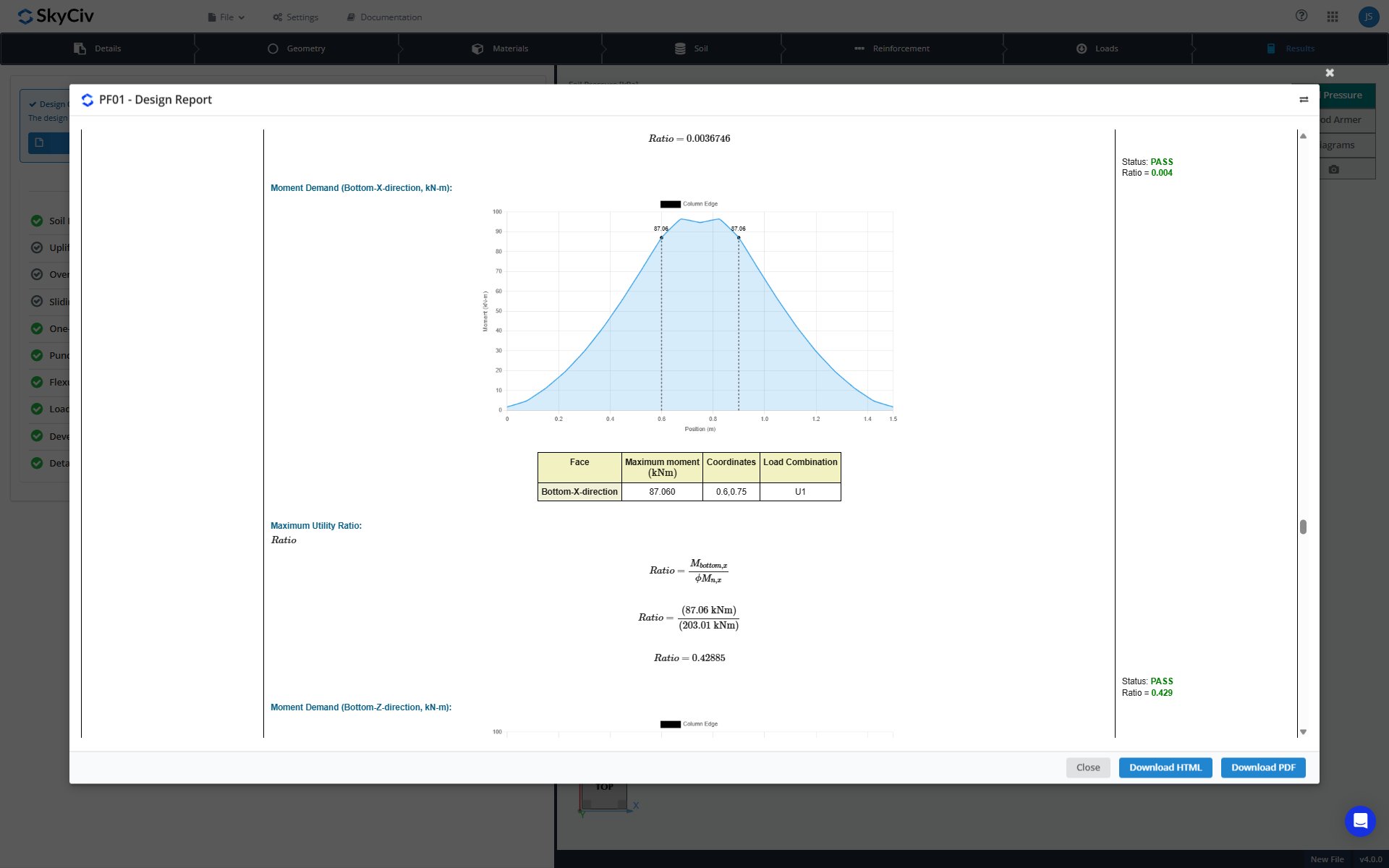
Once the design checks are complete, a summary view displays the tabulated utilization ratios for all design checks performed, based on the selected design code. A detailed report is also available, which can be downloaded as an HTML or PDF file. The PDF can be saved locally or stored in the cloud using the project manager.
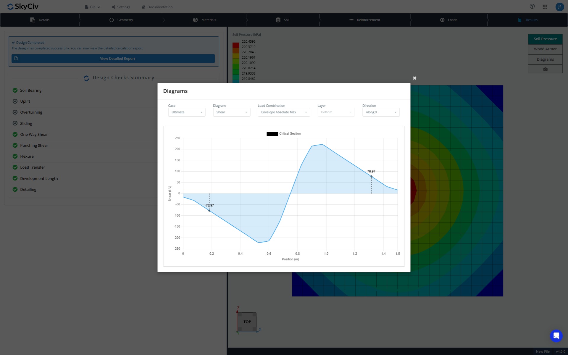
On the right panel, FEA results are displayed, including soil pressure and Wood-Armer moment results (a method used to design reinforcement for two-way slabs and footings). Shear and moment diagrams can also be viewed by clicking the Diagrams button.
SkyCiv Foundation Design Module streamlines the entire pad footing design process, from initial geometry and material setup through soil analysis, reinforcement detailing, and final code-based design checks. With support for major international design codes, συμπεριλαμβανομένου του ACI 318, ΟΠΩΣ ΚΑΙ 3600, CSA A23.3, and Eurocode EN2/EN7, the module provides a flexible workflow suited to a wide range of projects and regions. Combined with real-time 3D visualization and detailed FEA results, the platform allows engineers to design, verify, and report on isolated foundations efficiently, all within a single interface.
Θέλετε να δοκιμάσετε το λογισμικό Foundation Design του SkyCiv? Το εργαλείο μας επιτρέπει στους χρήστες να εκτελούν υπολογισμούς Foundation Design χωρίς λήψη ή εγκατάσταση!
Αναφορά:
- Απαιτήσεις κωδικού δόμησης για δομικό σκυρόδεμα (ACI 318-14) Σχολιασμός Απαιτήσεων Κτιριακού Κώδικα για Δομικό Σκυρόδεμα (ACI 318R-14). Αμερικανικό Ινστιτούτο Σκυροδέματος, 2014.
- Τέιλορ, Ανδρέας, et αϊ. Εγχειρίδιο ενισχυμένου σκυροδέματος: ένας σύντροφος στο ACI-318-14. Αμερικανικό Ινστιτούτο Σκυροδέματος, 2015.
