
A flange plate moment connection carries bending across a beam to column joint by turning the beam’s moment into a force couple: tension in one flange plate, συμπίεση στο άλλο. A separate web plate carries the shear. That division is what makes the connection straightforward to design and to build, because each component has one job.
The usual arrangement is a plate bolted to the beam flange and welded to the column. Where the frame is shop-assembled, the whole connection can be welded instead. The web plate is normally bolted at the beam web and welded to the column.
SkyCiv Connection Design checks the whole assembly to AISC 360-16 σε ASD ή LRFD. You enter the beam and column sections, the plate dimensions, the bolts and welds, and the loads; it returns every check with its utilization ratio and the clause behind it.
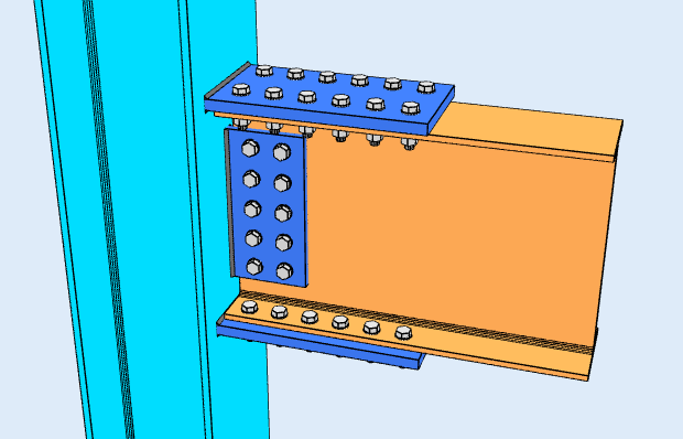
Υψόμετρο
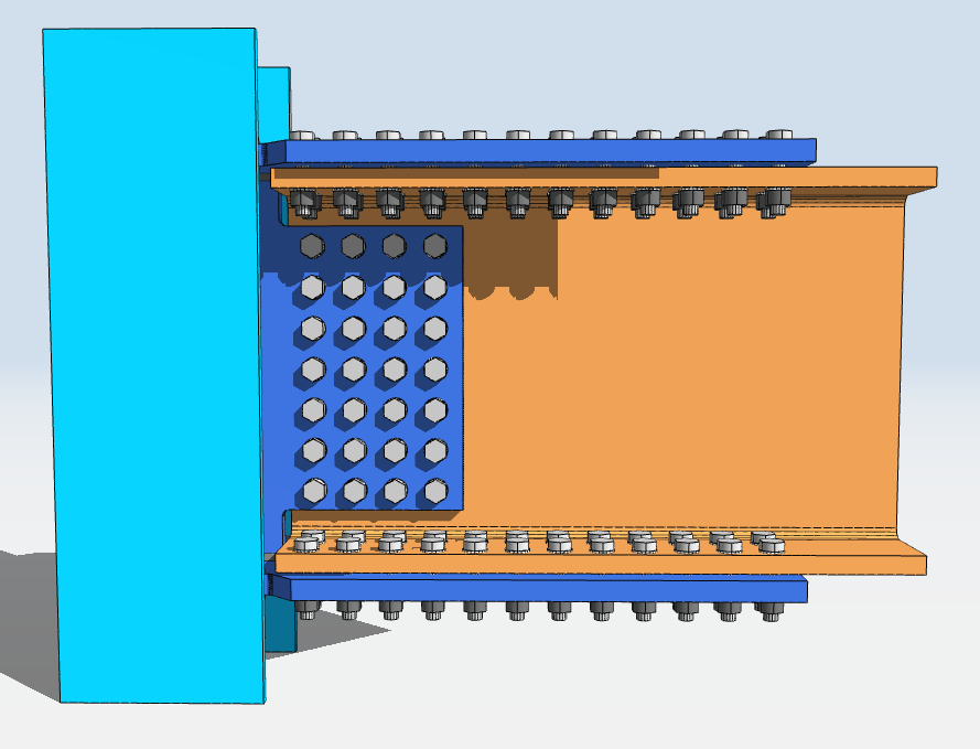
Κάτοψη
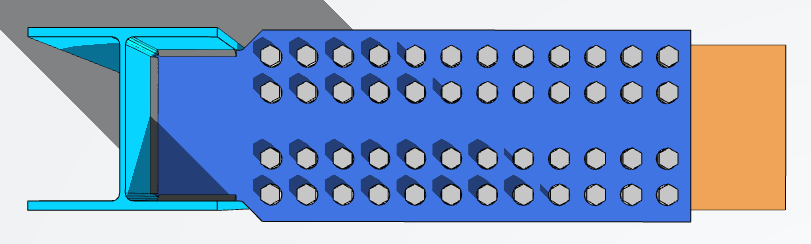
Designing a Flange Plate Connection in SkyCiv
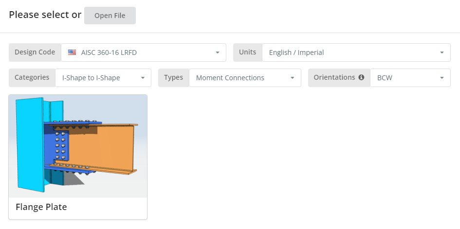
Ο κώδικας σχεδίασης μπορεί να είναι AISC 360-16 ASD ή LRFD, και μονάδες English/Imperial ή SI/Metric. Orientation is BCF or BCW; hover the tooltip for what each means. Κάντε κλικ στο “Πλάκα φλάντζας” πλακάκι.
Καρτέλα Λεπτομέρειες
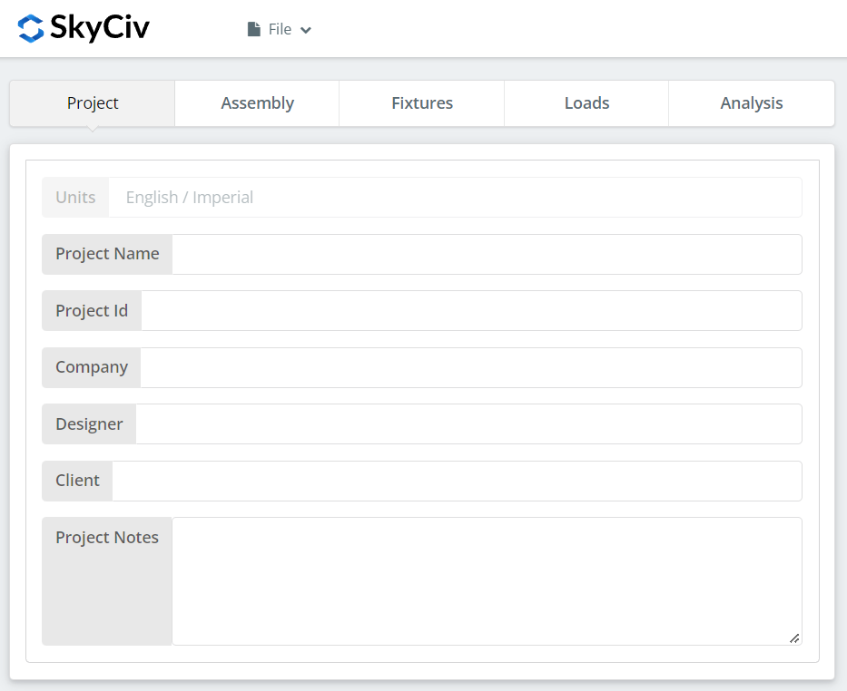
Καταγράψτε τις λεπτομέρειες του έργου εδώ. Τίποτα από αυτά δεν αλλάζει τους υπολογισμούς, αλλά εντάσσεται στην έκθεση.
Καρτέλα Συναρμολόγησης
Τρεις καρτέλες βρίσκονται κάτω από τη Συναρμολόγηση: the Column, the Beam, και η Σύνδεση, which holds both the flange plate and the web plate.
Καρτέλα στήλης
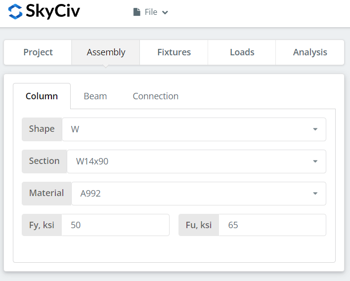
Specify the section and material grade of the column. A992 and A36 are in the list; for anything else choose Custom and enter Fy and Fu.
Καρτέλα δοκού
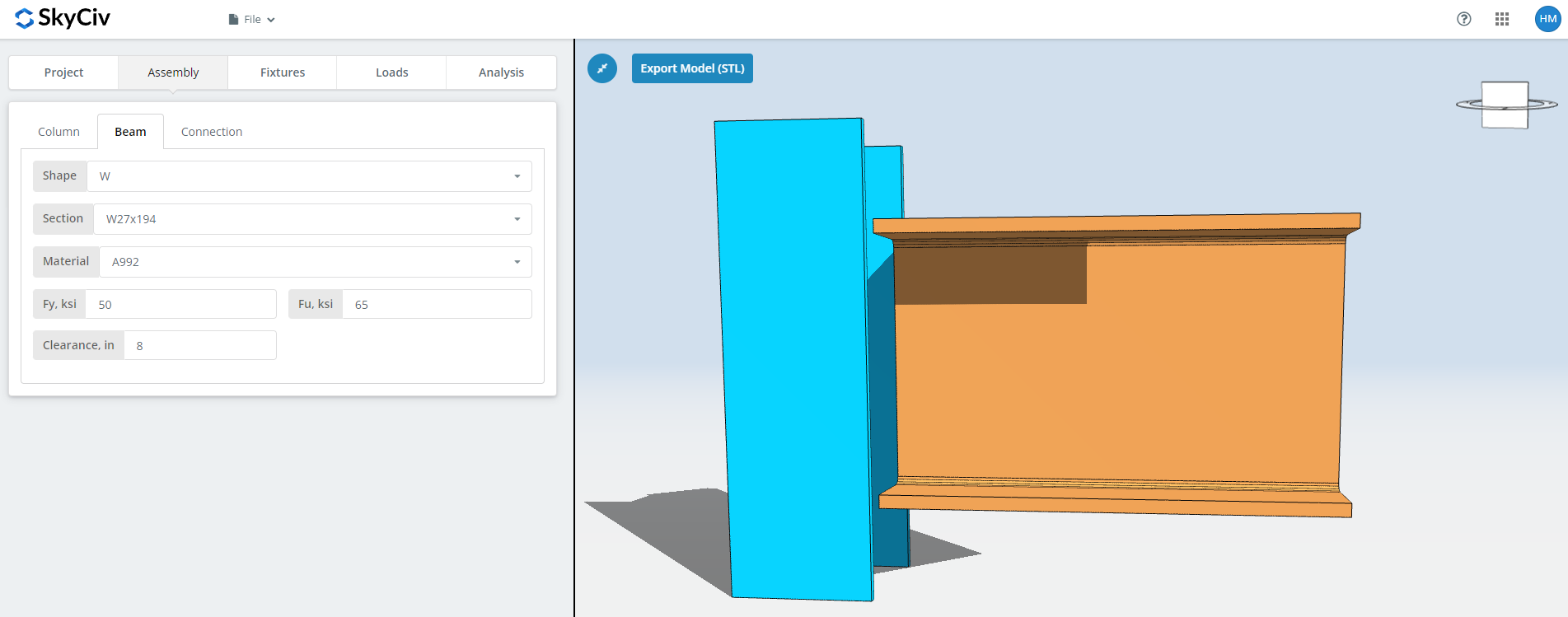
The same inputs for the beam, plus the beam clearance.
Καρτέλα Σύνδεση: Πλάκα φλάντζας
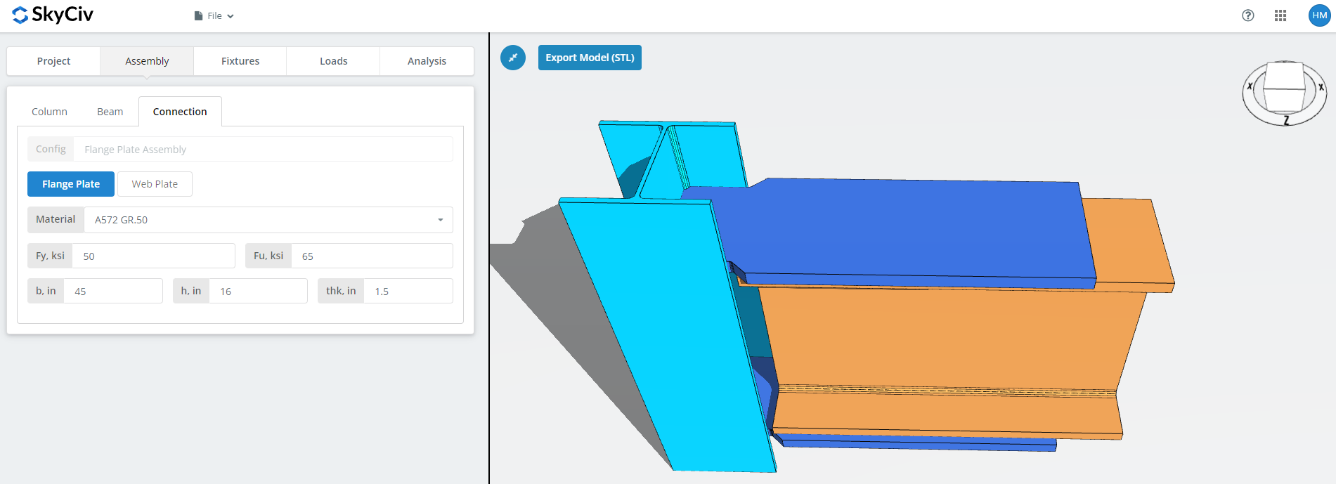
Set the flange plate properties: grade A36, A992 or A572 Gr.50, or Custom with your own Fy and Fu, then b (πλάτος), η (ύψος) και thk (πάχος).
This is the plate that carries the moment, so its area and the bolt group in it are what the moment capacity comes down to. Watch the 3D renderer as you type and check there is room for the bolts or welds you will define on the Fixtures tab.
Καρτέλα Σύνδεση: Πλάκα Ιστού
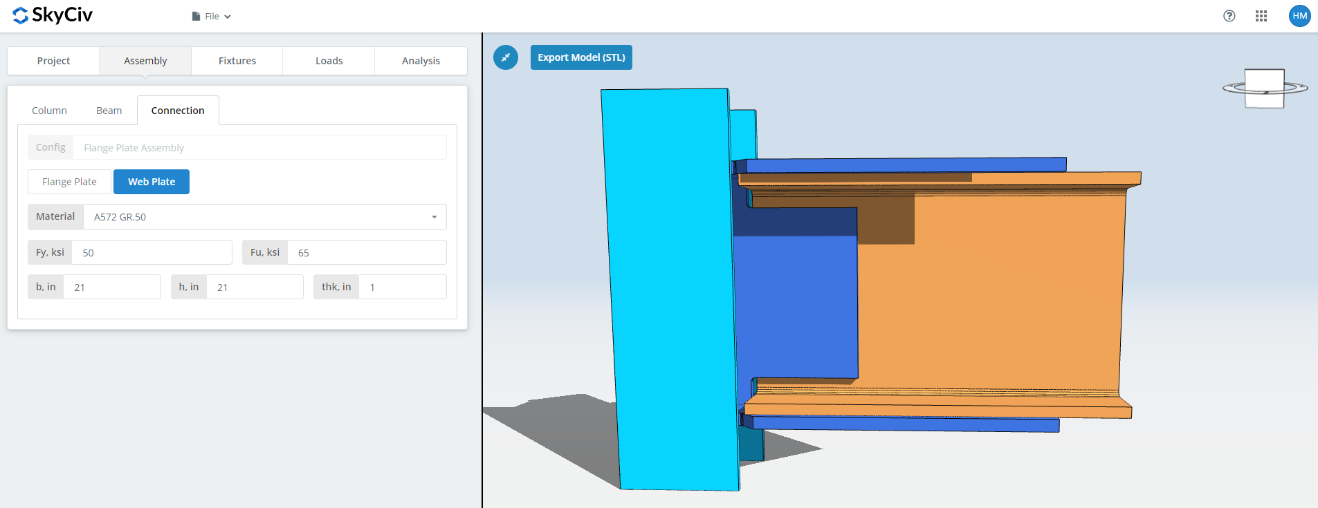
The same fields for the web plate. This one carries the shear, so its depth and bolt group are sized against the vertical load rather than the moment. Check the renderer again before moving on.
Γονικό Εξάρτημα 1 Αυτί
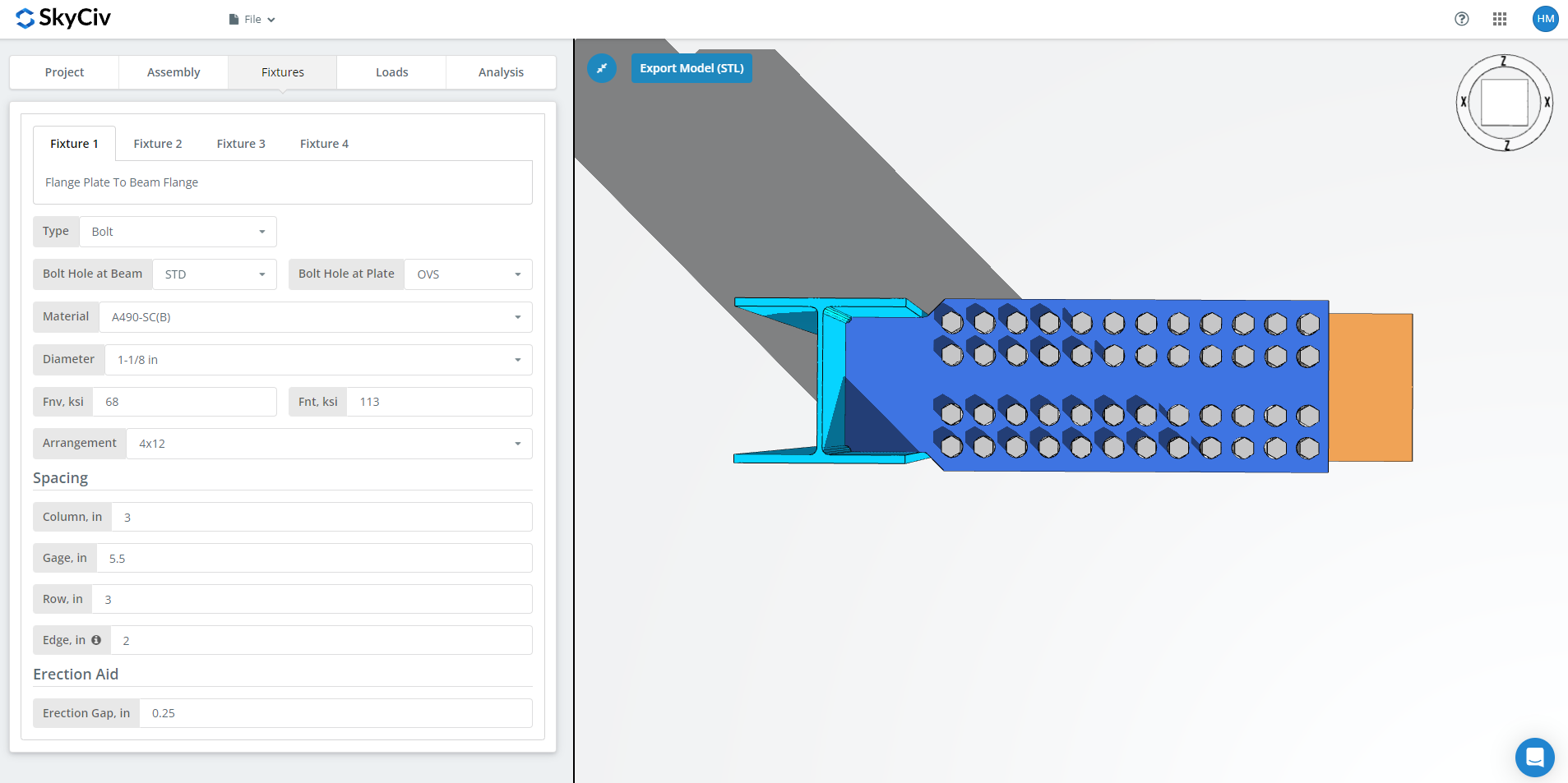
Γονικό Εξάρτημα 1 is the flange plate to beam flange connection. It can be bolted or welded; this walkthrough uses bolted.
Πρώτα, the bolt hole types at the beam flange and at the flange plate. Fabricators usually ask for standard holes (ΣΜΝ) in the member and oversized holes (OVS) in the flange plate, which buys fitting tolerance in the field.
Επόμενο, the bolt material or grade: A307, A325, A490 ή Custom. Τα A325 και A490 είναι βαθμοί εντός του ASTM F3125, το οποίο ενοποίησε τις παλαιότερες αυτόνομες προδιαγραφές. Choose N or X for a bearing-type connection and SC for slip-critical.
Slip-critical joints have lower design bolt capacity than bearing-type, so use them where slip actually matters: oversized or slotted holes, load reversal, or fatigue. Σε αυτό το παράδειγμα, using OVS holes in either the beam or the plate means the bolts are automatically checked as slip-critical. Between N and X, X gives the larger bolt shear capacity, but the threads must be excluded from the shear plane, and the erector has to know that. Between SC(ΕΝΑ) and SC(σι), SC(σι) gives the larger capacity and requires a more thoroughly prepared faying surface, for example SSPC-SP6 commercial blast cleaning.
Then the bolt diameter, from 5/8″ to 1-1/2″ or the metric equivalents, and the arrangement, μέχρι και 8 σειρές μπουλονιών και 12 κολώνες μπουλονιών, with the row spacing, column spacing and gage. ο “Σημειώστε ότι για αυτήν την κατεύθυνση ανέμου” input is the distance from the beam end to the first bolt column.
τελευταίος, the erection gap. This is the gap that lets the beam be dropped into place on site. It costs capacity, so specify it only where erection actually needs it, and say so on the drawing when you do.
Γονικό Εξάρτημα 2 Αυτί
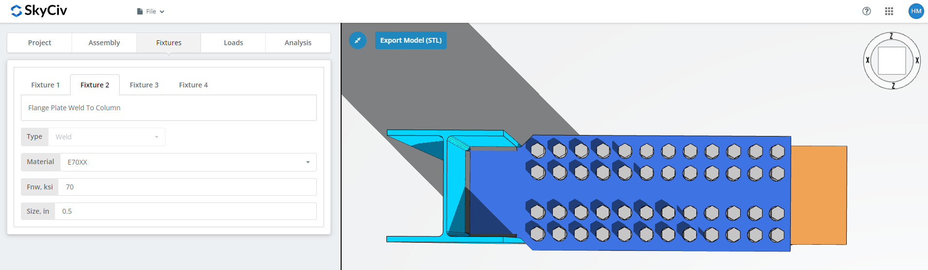
Γονικό Εξάρτημα 2 is the flange plate to column connection, to the column web and flange for BCW or to the column flange for BCF. This one is welded only.
Specify the weld material, or choose ‘Custom’ and enter Fnw if the electrode you want is not listed, then the weld size.
Γονικό Εξάρτημα 3 Αυτί
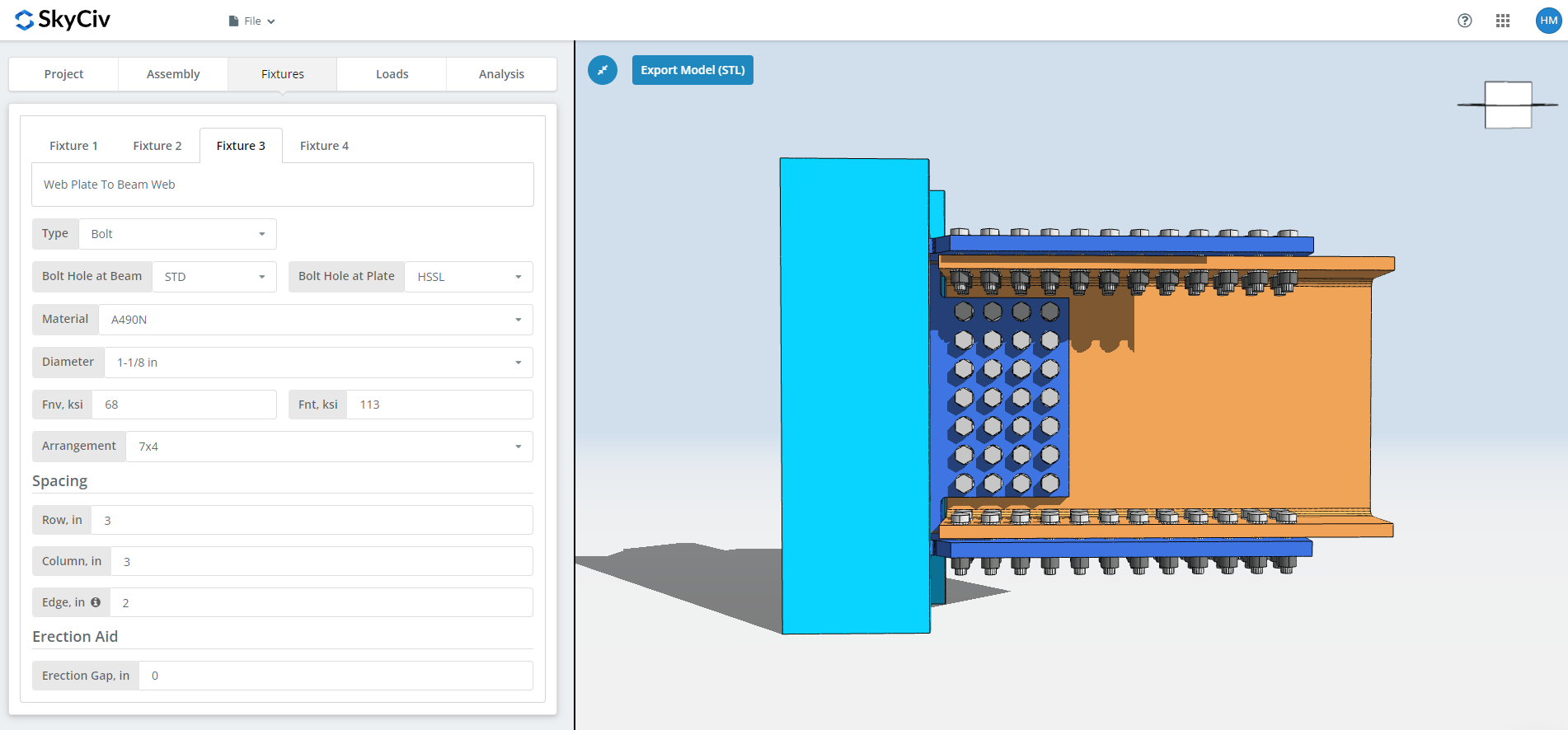
Γονικό Εξάρτημα 3 is the web plate to beam web connection. It can be bolted or welded; this walkthrough uses bolted.
Πρώτα, the bolt hole types at the beam web and at the web plate. Fabricators usually ask for standard holes (ΣΜΝ) in the member and horizontal short-slotted holes (HSSL) in the web plate.
Επόμενο, the bolt material or grade: A307, A325, A490 ή Custom, with the same N, X and SC choices as Fixture 1. The slip-critical and thread-exclusion notes above apply here too.
Then the bolt diameter, from 5/8″ to 1-1/2″ or the metric equivalents, and the arrangement, μέχρι και 12 σειρές μπουλονιών και 12 κολώνες μπουλονιών, with the row and column spacing. ο “Σημειώστε ότι για αυτήν την κατεύθυνση ανέμου” input is the distance from the beam end to the first bolt column.
τελευταίος, the erection gap, as above.
Γονικό Εξάρτημα 4 Αυτί
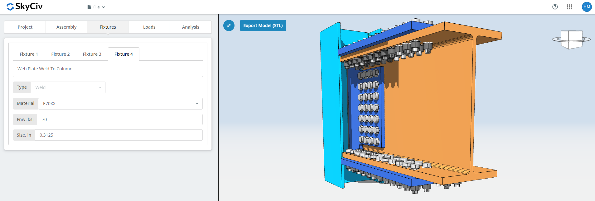
Γονικό Εξάρτημα 4 is the web plate to column web or flange connection, and like Fixture 2 it is welded only. Specify the weld material, ή «Προσαρμοσμένο’ με το δικό σας Fnw, και το μέγεθος της συγκόλλησης.
Για περισσότερα στην πλευρά του συνδετήρα, δείτε την τεκμηρίωση μπουλόνια και συγκολλήσεις.
Καρτέλα φορτίων
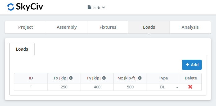
Enter the horizontal axial load under ‘Fx’, the vertical shear under ‘Fy’, and the strong axis moment under ‘Mz’.
Αντιστοιχίστε τα φορτία με τη μέθοδο σχεδιασμού που επιλέξατε στην αρχή. Το LRFD λαμβάνει συντελεστή φορτία έναντι της αντοχής σχεδιασμού; Η ASD δέχεται τα φορτία σέρβις σε σχέση με την επιτρεπόμενη αντοχή. Το λογισμικό δεν μπορεί να πει τι πληκτρολογήσατε.
Αποτελέσματα Αποτελέσματα
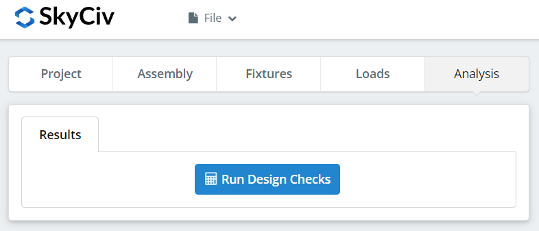
Κάντε κλικ “Εκτελέστε ελέγχους σχεδιασμού”. Οτιδήποτε λείπει από τις προηγούμενες καρτέλες επισημαίνεται εδώ αντί να προεπιλεγεί σιωπηλά.
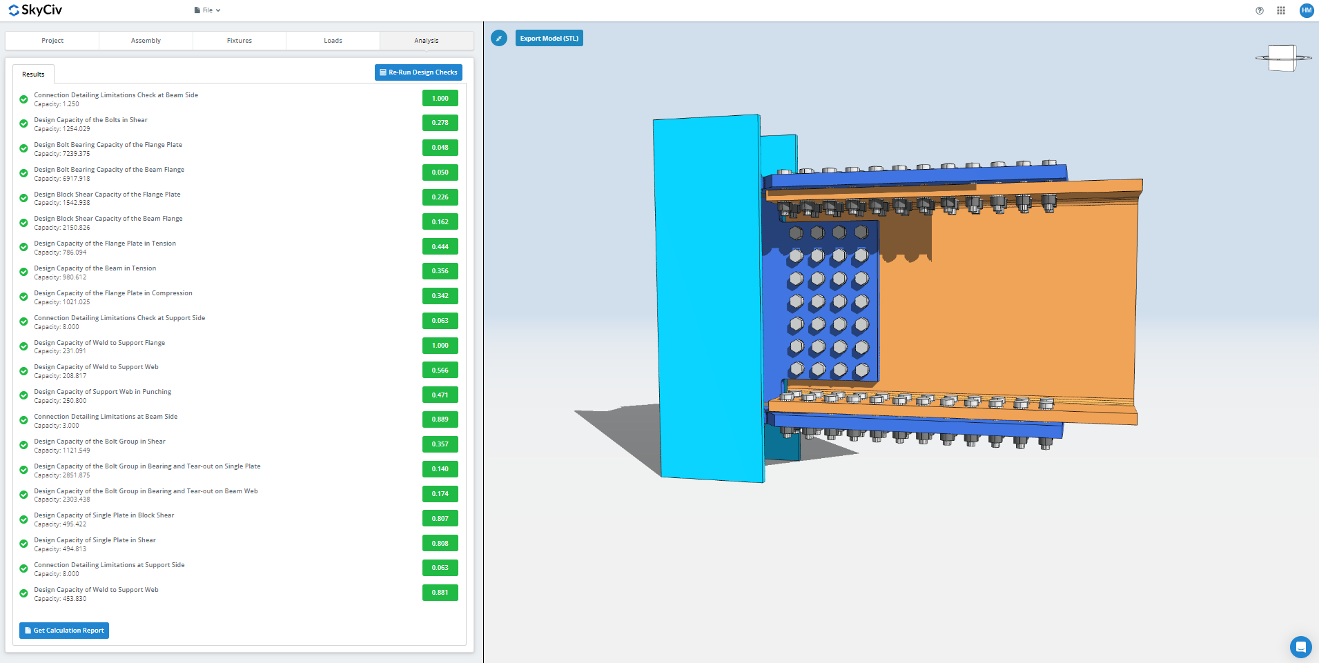
Η σύνοψη δείχνει εάν η σύνδεση πέρασε, με αναλογία χρησιμοποίησης σε κάθε έλεγχο. Αν απέτυχε, αλλάξτε τις εισόδους στις προηγούμενες καρτέλες και κάντε κλικ “Επανεκτέλεση ελέγχων σχεδίασης”. Όταν περάσει, “View Calculation Report” opens the detailed report.
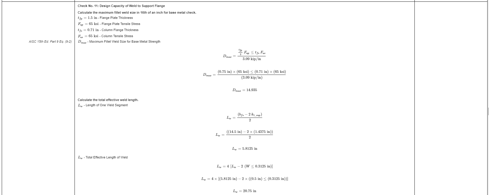
That is an extract from the report. Κάθε έλεγχος φέρει την αναφορά του στο εγχειρίδιο ή τις προδιαγραφές της AISC, και η εργασία ακολουθεί τη σειρά που χρησιμοποιεί η προδιαγραφή, έτσι ένας αναθεωρητής μηχανικός μπορεί να το διαβάσει γραμμή προς γραμμή αντί να αναστρέψει έναν αριθμό.
Ακολουθεί ένα αντίγραφο PDF της πλήρους λεπτομερούς αναφοράς υπολογισμού: Έκθεση σχεδίασης σύνδεσης.
Δοκιμάστε το μόνοι σας
Pick the flange plate connection, εισάγετε τις ενότητες σας, πλάκες, bolts and loads, και δείτε κάθε έλεγχο με τον κωδικό αναφοράς του. Εκτελείται στο πρόγραμμα περιήγησης, χωρίς τίποτα για εγκατάσταση.
Δείτε επίσης το flange plate connection calculator, ο moment connection calculator και το στιγμιαίες συνδέσεις ΣΦΑΙΡΙΚΗ ΕΙΚΟΝΑ.
