
A column splice joins one column to the one above it. Columns arrive in mill lengths, and a building taller than that length needs its columns spliced, usually a few feet above floor level where the erector can reach the joint from the deck. Splices also turn up in retrofit work, where a column is extended, replaced or reinforced after a change in loading.
The splice has to carry whatever the column carries across the joint: axial compression, axial tension where uplift or overturning governs, κουρεύω, και στιγμή. AISC 360-16 sets out the procedures for each. This page walks through designing one in SkyCiv Connection Design.
Οι υπολογισμοί πίσω από τις συνδέσεις συνδέσεως στηλών
A column splice is a slow connection to calculate by hand. Each plate has to be checked in tension, compression and bearing, each bolt group in shear, and the whole joint for block shear, all of it doubled because the upper and lower columns are separate connections either side of the splice. AISC 360-16 gives the procedure for the axial, shear and moment capacity of each of those pieces.
ο column splice calculator runs the same procedure. You supply the column sections, μεγέθη πλάκας, bolt specifications and loads, and it returns every check with its utilization ratio and the clause it came from, so the arithmetic stops being the part of the job that takes the time.
Βιδωτό ή συγκόλληση: Επιλέγοντας τη σωστή μέθοδο σύνδεσης
Bolting is the usual choice for a column splice. A bolted splice is made in the air by an erector with a wrench, it tolerates the small misalignments that come with erecting a frame, and it can be slackened and adjusted if something does not line up. Welding a splice at height means preheat, position welding and inspection on a joint that is hard to reach.
Προετοιμασία της επιφάνειας επαφής στήλης: ο “Fit to Bear” Πλησιάζω
Where the column ends are prepared so the two sections sit in full contact, compression transfers through bearing rather than through the bolts. That usually means fewer bolts and thinner plates, because the plates only have to carry tension, διάτμηση και ροπή.
It is a decision that has to reach the fabricator. Fit to bear is a preparation requirement on the shop drawings, not something the connection design can assume on its own, so if you design on that basis, say so on the drawing.
Η ανάγκη για συνδέσεις συνδέσεως στηλών
Splices appear wherever a column cannot be a single piece: buildings taller than the available mill length, sections that would be impossible to ship or lift in one, and retrofits where a column is extended or strengthened. In each case the splice has to reproduce the continuity the column would have had without it.
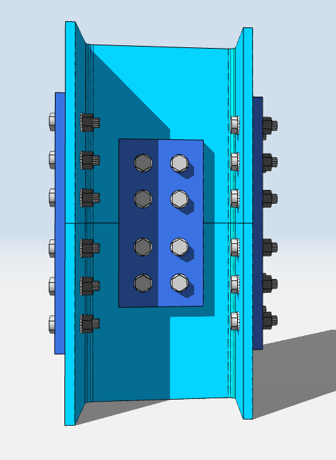
Designing a Column Splice in SkyCiv
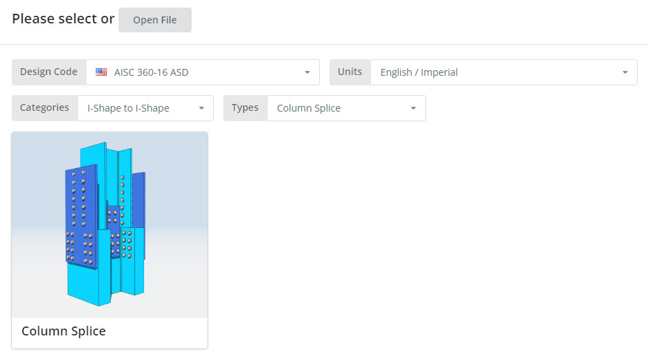
Ο κώδικας σχεδίασης μπορεί να είναι AISC 360-16 ASD ή LRFD, και μονάδες English/Imperial ή SI/Metric. Κάντε κλικ στο “Στήλη Splice” πλακάκι.
Καρτέλα Λεπτομέρειες
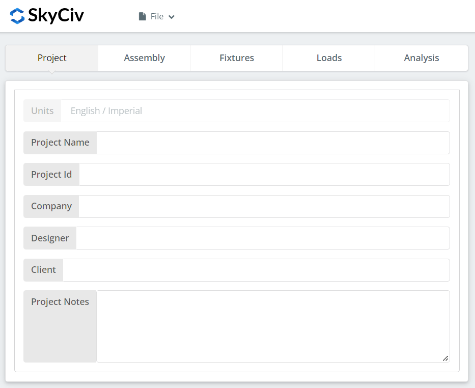
Καταγράψτε τις λεπτομέρειες του έργου εδώ. Τίποτα από αυτά δεν αλλάζει τους υπολογισμούς, αλλά εντάσσεται στην έκθεση, which is what makes a set of designs traceable later.
Καρτέλα Συναρμολόγησης
Τρεις καρτέλες βρίσκονται κάτω από τη Συναρμολόγηση: the Lower Column, the Upper Column, και η Σύνδεση, which holds the flange plate and web plate.
Καρτέλα κάτω στήλης
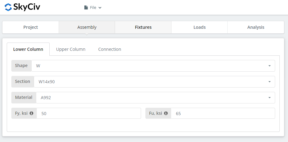
Specify the section and material grade of the lower column. A992 and A36 are in the list; for anything else choose Custom and enter Fy and Fu.
Καρτέλα άνω στήλης
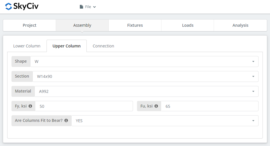
The same inputs, plus the option to declare the columns fit to bear. Επιλέγω “ΝΑΙ” and the compressive load is designed at the column contact surface instead of through the bolted connection, which gives a more economical connection. Οπως παραπάνω, that is a requirement you have to pass to the fabricator: the columns must actually be prepared to bear.
Καρτέλα Σύνδεση: Πλάκα φλάντζας
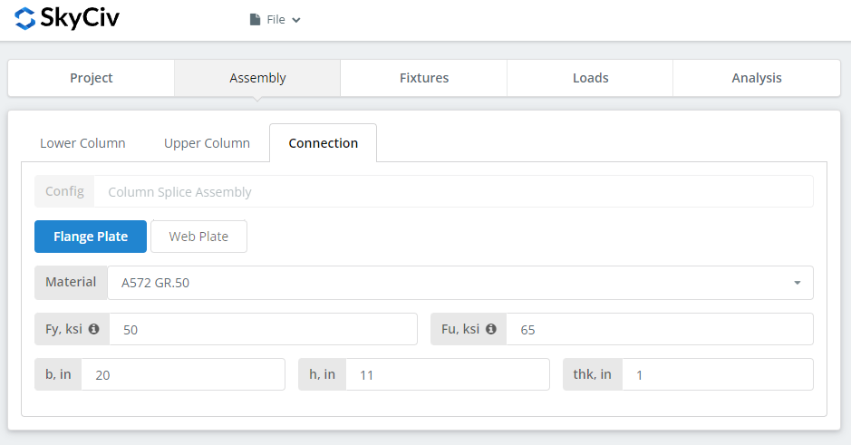
Set the flange plate properties: grade A36, A992 or A572 Gr.50, or Custom with your own Fy and Fu, then b (πλάτος), η (ύψος) και thk (πάχος). Watch the 3D renderer as you type and check the plate geometry makes sense, in particular that there is room for the bolt group you are about to define on the Fixtures tab.
Καρτέλα Σύνδεση: Πλάκα Ιστού
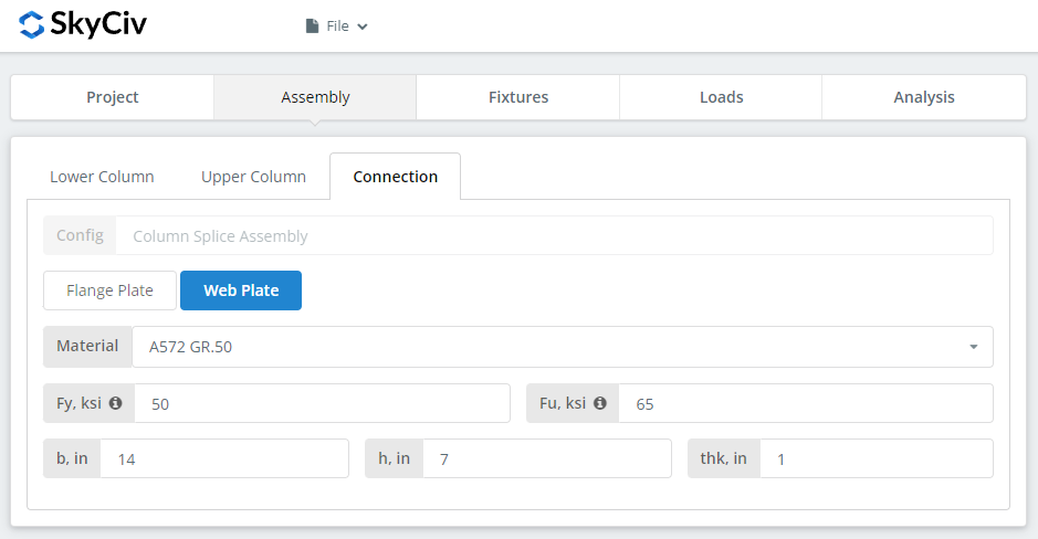
Same inputs as the flange plate. Check the renderer again before moving on.
Γονικό Εξάρτημα 1-4 Αυτί
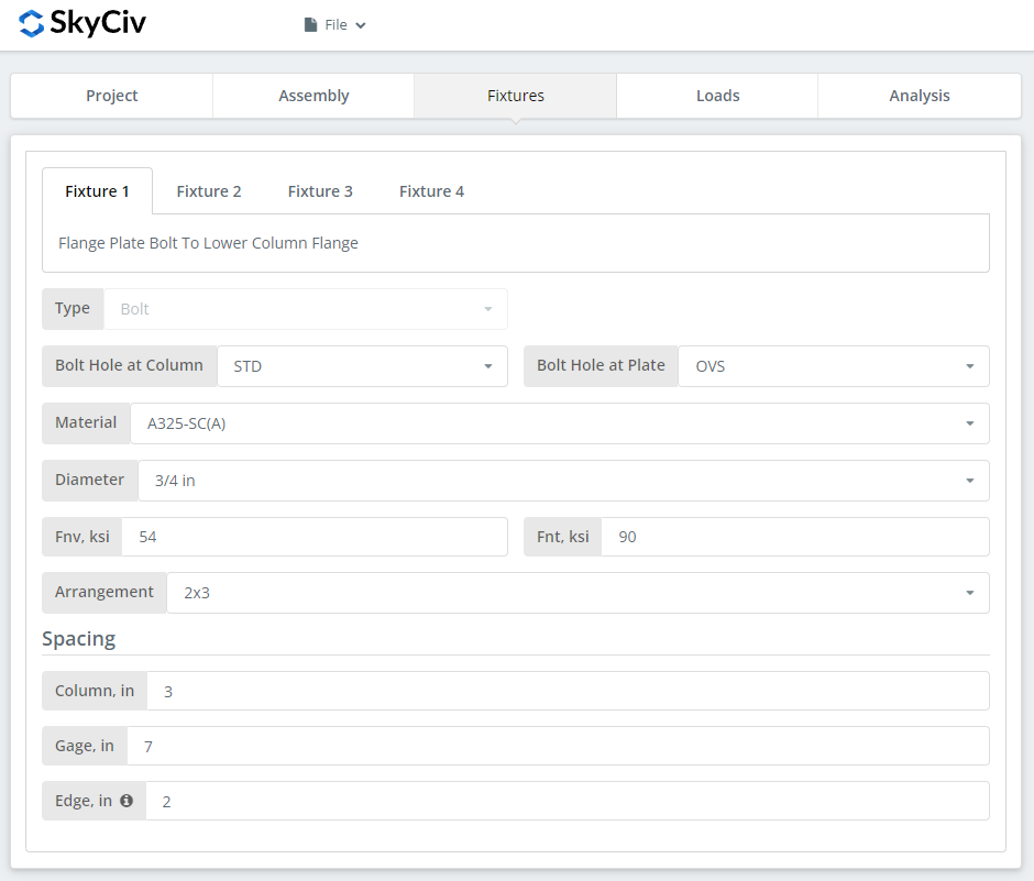
This is where the bolts are defined, one fixture per interface:
Γονικό Εξάρτημα 1 – Πλάκα φλάντζας στη φλάντζα κάτω στήλης
Γονικό Εξάρτημα 2 – Πλάκα φλάντζας σε φλάντζα άνω στήλης
Γονικό Εξάρτημα 3 – Πλάκα Ιστού στον Ιστό κάτω στήλης
Γονικό Εξάρτημα 4 – Πλάκα Ιστού στον Ιστό της επάνω στήλης
Πρώτα, the bolt-hole types at the column flange or web and at the plates. Fabricators usually ask for standard holes (ΣΜΝ) in the member and oversized holes (OVS) in the plate, which buys fitting tolerance in the field.
Επόμενο, the bolt material or grade: A307, A325, A490 ή Custom. Τα A325 και A490 είναι βαθμοί εντός του ASTM F3125, το οποίο ενοποίησε τις παλαιότερες αυτόνομες προδιαγραφές, so a drawing calling for A325 is calling for F3125 Grade A325. Choose N or X for a bearing-type connection and SC for slip-critical.
Slip-critical joints have lower design bolt capacity than bearing-type, so use them where slip actually matters: oversized or slotted holes, load reversal, or fatigue. Σε αυτό το παράδειγμα, using OVS holes in either the column or the plate means the bolts are automatically checked as slip-critical. Between N and X, X gives the larger bolt shear capacity, but the threads must be excluded from the shear plane, which the erector has to know about. Between SC(ΕΝΑ) and SC(σι), SC(σι) gives the larger capacity and requires a more thoroughly prepared faying surface, for example SSPC-SP6 commercial blast cleaning.
Then the bolt diameter, from 5/8″ to 1-1/2″ or the metric equivalents, and the arrangement, μέχρι και 8 σειρές μπουλονιών και 12 κολώνες μπουλονιών. Set the bolt row spacing, column spacing and gage. ο “Σημειώστε ότι για αυτήν την κατεύθυνση ανέμου” input is the distance from the column end to the first bolt column.
For more on the fastener side of this, δείτε την τεκμηρίωση μπουλόνια.
Καρτέλα φορτίων
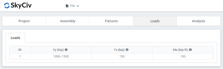
Enter the compressive or tensile load as ‘Fy’, the horizontal shear as ‘Fz’, and the strong axis moment as ‘Mx’. Τοποθετήστε το δείκτη του ποντικιού στις συμβουλές εργαλείων για τη σύμβαση και την κατεύθυνση του καθενός.
Αντιστοιχίστε τα φορτία με τη μέθοδο σχεδιασμού που επιλέξατε στην αρχή. Το LRFD λαμβάνει συντελεστή φορτία έναντι της αντοχής σχεδιασμού; Η ASD δέχεται τα φορτία σέρβις σε σχέση με την επιτρεπόμενη αντοχή. Το λογισμικό δεν μπορεί να πει τι πληκτρολογήσατε, so mixing them produces a utilization ratio that means nothing.
Αποτελέσματα Αποτελέσματα
Κάντε κλικ “Εκτελέστε ελέγχους σχεδιασμού”. Οτιδήποτε λείπει από τις προηγούμενες καρτέλες επισημαίνεται εδώ αντί να προεπιλεγεί σιωπηλά.
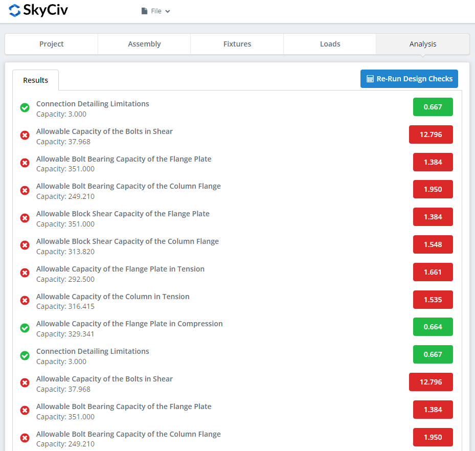
Η σύνοψη δείχνει εάν η σύνδεση πέρασε, with a utilization ratio against each check and the governing one called out. Αν απέτυχε, αλλάξτε τις εισόδους στις προηγούμενες καρτέλες και κάντε κλικ “Επανεκτέλεση ελέγχων σχεδίασης”. Όταν περάσει, “View Calculation Report” opens the detailed report.
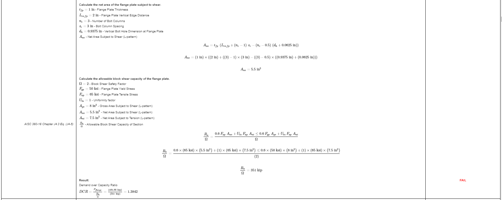
That is an extract from the report. Κάθε έλεγχος φέρει την αναφορά του στο εγχειρίδιο ή τις προδιαγραφές της AISC, and the working is laid out the way the specification lays it out, so a reviewing engineer can follow it line by line instead of reverse-engineering a result.
ΕδώΕίναι ένα αντίγραφο PDF της πλήρους λεπτομερούς αναφοράς υπολογισμού.
Designing a beam splice instead? ο beam splice calculator works the same way.
Δοκιμάστε το μόνοι σας
The link below opens the module with the column splice already loaded. Enter your sections, πλάκες, bolts and loads, and every check and code reference is shown in full. Εκτελείται στο πρόγραμμα περιήγησης, χωρίς τίποτα για εγκατάσταση.
