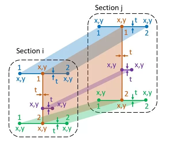
Κάθε μέλος έχει ένα αρχικό τμήμα i και ένα τελικό τμήμα j. Ένα τμήμα αποτελείται από γραμμές που ορίζονται από δύο κόμβους, Χ,y στο επίπεδο του τμήματος. Κάθε γραμμή έχει ένα ξεχωριστό πάχος t και ανήκει σε μια συγκεκριμένη ομάδα υλικών. Το σημείο αναφοράς για το x,Οι συντεταγμένες y μπορούν να επιλεγούν αυθαίρετα στο χώρο για κάθε τμήμα. Ο αριθμός των γραμμών σε κάθε ενότητα πρέπει να είναι συνεπής. Τα δεδομένα για τον πίνακα μπορούν είτε να εισαχθούν με μη αυτόματο τρόπο είτε να εισαχθούν από ένα φύλλο Excel. Επιπροσθέτως, Τα σχήματα ενοτήτων μπορούν να εισαχθούν από ένα αρχείο DXF που είναι αποθηκευμένο στον υπολογιστή του χρήστη.
Ενημέρωση t: Το κοινό πάχος μπορεί να αλλάξει για επιλεγμένη ομάδα γραμμών
Ενημέρωση Mat.: Η κοινή ομάδα υλικού μπορεί να αλλάξει για επιλεγμένη ομάδα γραμμών
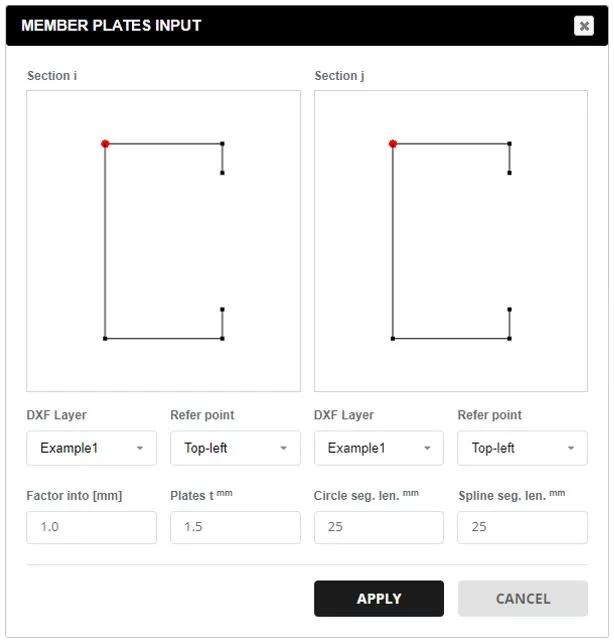
Δεδομένα από το DXF.: Επιλέξτε ένα αρχείο DXF από τον υπολογιστή σας. Επιλέξτε το επιθυμητό επίπεδο για τα στοιχεία ενότητας. Το σημείο αναφοράς καθορίζει την προέλευση για το Χ,και συντεταγμένες. Χρησιμοποιήστε τον παράγοντα για να κλιμακώσετε τις συντεταγμένες τομής σε χιλιοστά. Ένα προεπιλεγμένο πάχος θα εφαρμοστεί σε όλες τις γραμμές, που μπορεί να τροποποιηθεί αργότερα. Οι υποστηριζόμενες οντότητες DXF περιλαμβάνουν: Γραμμές, Πολυγραμμές, τόξα, και Splines. Για τόξα και σφήνες, Η διαίρεση τμήματος καθορίζεται για να ταιριάζει με το προτιμώμενο μέγεθος πλέγματος.
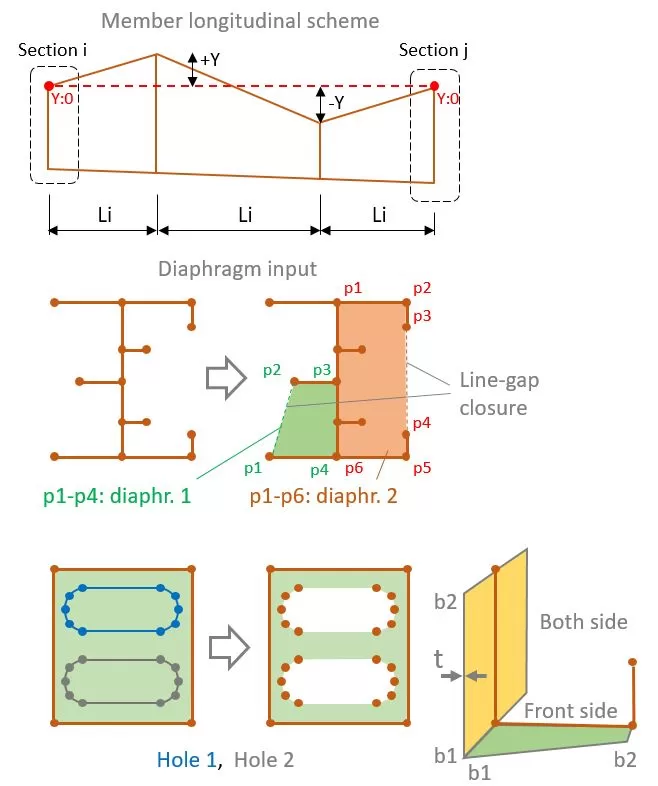
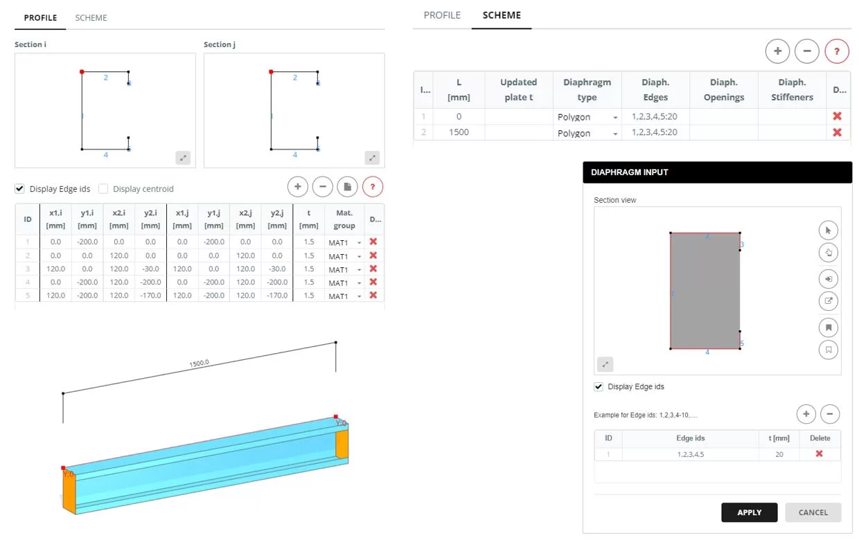
Ολόκληρο το μέλος μπορεί να αναπαρασταθεί είτε με ένα μόνο μήκος L είτε από μια σειρά τμημάτων Li. Ανεξάρτητα από τον αριθμό των τμημάτων, οι γραμμές του τμήματος έναρξης και λήξης θα έχουν τις ίδιες συντεταγμένες όπως ορίζονται στην καρτέλα ΠΡΟΦΙΛ. Κάθε τμήμα μπορεί επίσης να έχει διαφορετική θέση Υ.
Για κάθε τμήμα όπου μεγάλο δεν ισούται με 0, το πάχος για μια ομάδα πλακών μπορεί να ενημερωθεί στη στήλη "Ενημερωμένη πλάκα t". Επίλεξε το 0 για να κρύψει το πιάτο και τιμή μεγαλύτερη από 0 για να τροποποιήσετε το πάχος (τ).
Για τμήματα τμήματος, ένα διάφραγμα μπορεί να προστεθεί εάν το «Πολύγωνο’ επιλέγεται ο τύπος. Για να καθορίσετε ένα ή περισσότερα διαφράγματα, επιλέξτε τις γραμμές που συνθέτουν το σχήμα. Μόνο ένα κλείσιμο με διάκενο γραμμής επιτρέπεται να σχηματίσει το σχήμα.
Τρύπες μπορούν επίσης να ενσωματωθούν μέσα στο διάφραγμα. Για να το κάνω αυτό, ορίστε τα σχήματα των οπών επιλέγοντας τις αντίστοιχες γραμμές που περικλείουν τις τρύπες.
Εάν έχει καθοριστεί διάφραγμα, τότε μπορούν επίσης να οριστούν φλάντζες ή ενισχυτικά επιλέγοντας τις σχετικές γραμμές τους. Κάθε φλάντζα ή ενισχυτικό έχει ένα πλάτος έναρξης και λήξης (β1,σι2), πάχος τ, και ομάδα υλικού.
Παράδειγμα
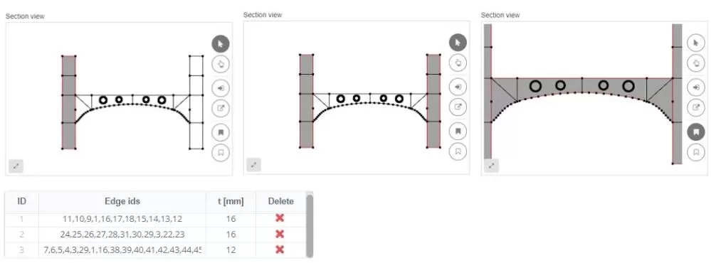
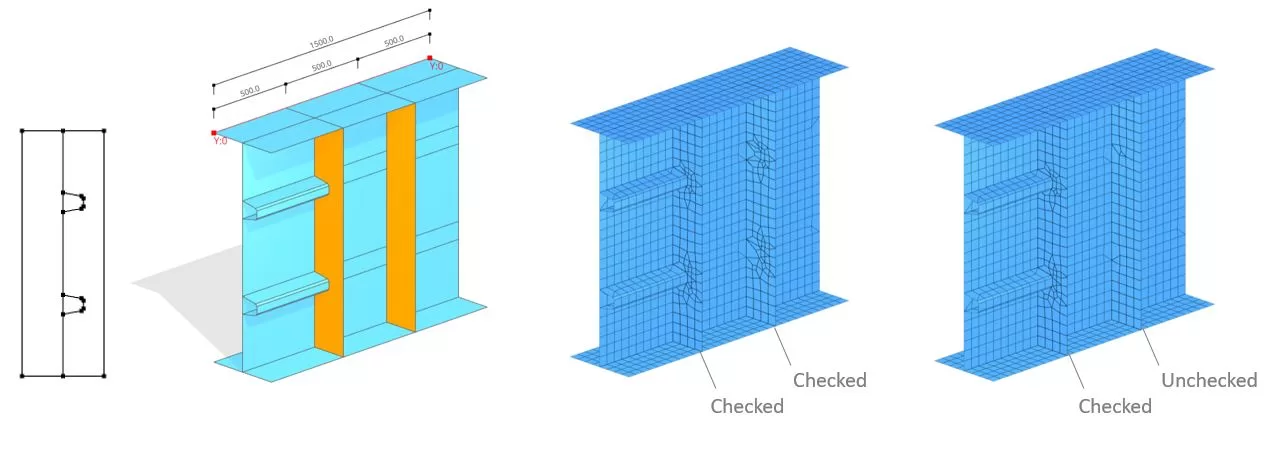
Κατά τη διάταξη των άκρων μέσα σε ένα διάφραγμα, μπορούν να συνυπολογιστούν στο σχέδιο πλέγματος. Για παράδειγμα, μπορεί να προκύψει μια κατάσταση όπου μια διαμήκης ακαμψία συνδέεται με μια κατακόρυφη. Σε τέτοια σενάρια, τα «εσωτερικά άκρα’ η επιλογή πρέπει να ενεργοποιηθεί. Ωστόσο, εάν η κατακόρυφη ενίσχυση δεν είναι συνδεδεμένη σε τίποτα, αυτή η επιλογή μπορεί να απενεργοποιηθεί.