
Οι χαλύβδινες συνδέσεις που αναφέρονται σε αυτό το άρθρο έχουν σχεδιαστεί σύμφωνα με το Αυστραλιανό Πρότυπο ΟΠΩΣ ΚΑΙ 4100:2020, Εγχειρίδιο σύνδεσης του Australian Steel Institute 1, και οδηγοί σχεδίασης του Australian Steel Institute 1-5.
Scope of the AS 4100 Μονάδα μέτρησης
Before going through the connection types, it is worth being clear about what the module covers under AS 4100.
ΟΠΩΣ ΚΑΙ 4100:2020 design in SkyCiv is for shear connections between I-sections, in metric units. Στιγμιαίες συνδέσεις, splices and bracing connections are outside the current AS 4100 scope.
Universal Beam σε Universal Column
Beam to column connections are among the most common connection types in steel design. The AS connections in SkyCiv are built around a supported beam framing into a supporting member, and the orientation can be set to a column flange support, a column web support, or a beam web support.
That third orientation means the same four connection types can also be used beam to beam, not only beam to column.
Only one connection to a node can be designed at a time. Όταν πρόκειται για συνδέσεις back-to-back, Συνιστάται να λαμβάνετε συντηρητικές υποθέσεις για τη διαδρομή φορτίου.
Διατμητικές συνδέσεις
A shear connection is a simple connection. It is detailed to carry the beam end reaction and to rotate at the joint rather than to carry end moment, which is what separates it from a moment connection. In the AS module it is designed for shear alone, with no concurrent axial load.
Για το σχέδιο AS, the following shear connection types are available:
Each of the four is available beam to column flange, beam to column web, and beam to beam web.
-

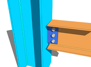
- Web Side Plate – Φλάντζα δοκού σε στήλη
-
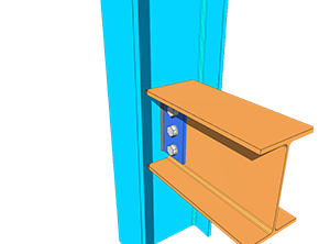
- Web Side Plate – Ιστός από δοκό σε στήλη
-
- Εύκαμπτη πλάκα άκρης – Φλάντζα δοκού σε στήλη

-
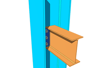
- Εύκαμπτη πλάκα άκρης – Ιστός από δοκό σε στήλη
-
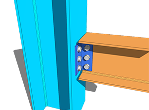
- Μονή γωνία – Φλάντζα δοκού σε στήλη
-
- Μονή γωνία – Ιστός από δοκό σε στήλη
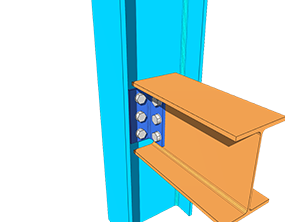
-
- Διπλή γωνία – Φλάντζα δοκού σε στήλη
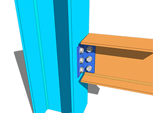
-
- Διπλή γωνία – Ιστός από δοκό σε στήλη
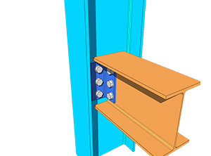
The design of the above shear connections was based mainly on ASI Design Guides 3, 4 και 5. The reference formulas were taken from the AS 4100:2020 εγχειρίδιο, while the rest of the calculations and criteria were taken from the ASI Connection Handbook 1.
Συντελεστής ομάδας μπουλονιών
Για ευελιξία στη διάταξη των μπουλονιών και στην απόσταση των μπουλονιών, Το SkyCiv προσάρμοσε τη μέθοδο ICOR και την ανελαστική ανάλυση για τον προσδιορισμό του συντελεστή C της ομάδας μπουλονιών, which is then used to calculate the bolt group shear capacity and bolt bearing capacity.
The Instantaneous Centre of Rotation Method (ICOR) χρησιμοποιεί επανάληψη για να εντοπίσει το IC της ομάδας μπουλονιών. Το SkyCiv χρησιμοποιεί τον δικό του λύτη για αυτές τις επαναλήψεις. Η θέση του IC περιλαμβάνεται στους υπολογισμούς, but the iterations are not shown, to keep the report concise and readable.
The equation used to calculate the force per bolt using the inelastic analysis is based on AISC Eq. (7-1) στη σελίδα 7-7 του Εγχειριδίου AISC 15th Edition. Η εξίσωση φαίνεται παρακάτω.
[math] R = R_{ult}\left(1-e^{-10\Delta}\right)^{0.55} [math]
This is a method borrowed for the bolt group solver, not a change of design code. The capacities themselves are still checked to AS 4100:2020.
Δεδομένου ότι η χωρητικότητα της ομάδας μπουλονιών προσάρμοσε τη μέθοδο AISC, the provisions for determining the design bolt eccentricity of the bolt group also follow Table 10-9 της AISC 15th Ed. This applies to SkyCiv’s AS Web Side Plate connection.
Eccentricity is handled differently for each type. Για συνδέσεις μονής γωνίας, both the NSL and OSL legs are designed with load eccentricity. Για συνδέσεις διπλής γωνίας, only the NSL leg is designed with eccentricity, since the OSL leg is symmetrically balanced about the line of force. For Flexible End Plate connections there is no eccentricity either, as the load acts directly on the centre of the bolt group. Every bolt group without eccentricity takes the bolt coefficient C as the total number of bolts in the group.
Τύποι εξαρτημάτων
Each interface can be set as a bolted or a welded fixture, at the beam and at the support.
For the bolted case, δείτε την τεκμηρίωση μπουλόνια; for the welded case, βλέπω συγκολλήσεις.
Περιορισμοί λεπτομερειών
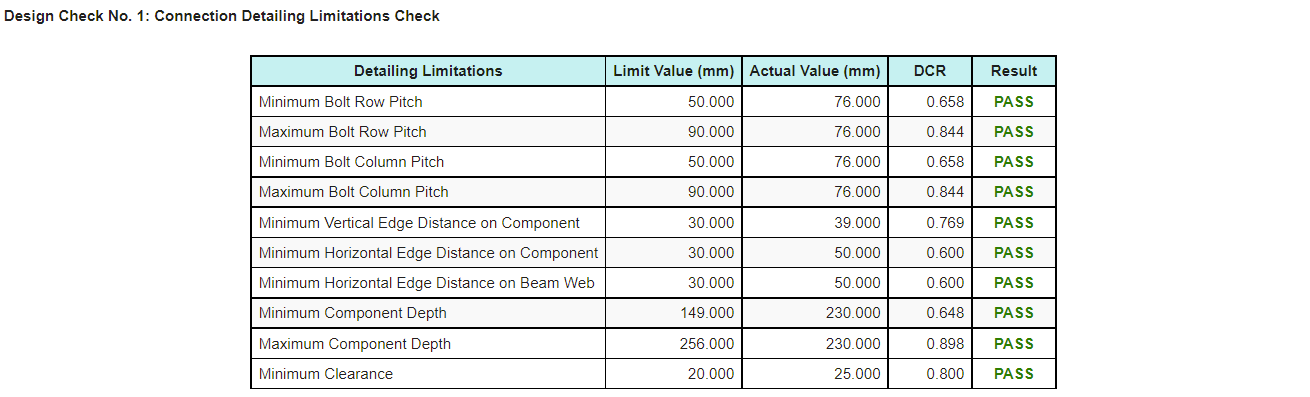
Detailing limitations, the fit-up checks on the connections, are included in the AS connection design. Most of them are based on ASI Design Guides 3-5, while some follow an intuitive engineering approach.
These checks catch the connection that satisfies every strength calculation and still cannot be built or erected, which is a failure mode that strength checks alone will not find.
A pass or fail result for the detailing limitations appears on the Results tab, so it can be identified quickly. Η αναφορά υπολογισμού παράγει επίσης έναν πίνακα, Φαίνεται παρακάτω, so the item that needs to be modified is easy to pick out.
Περισσότεροι τύποι σύνδεσης
Should you wish to see more connection types added under AS 4100, μπορείτε να επικοινωνήσετε Υποστήριξη SkyCiv.
Try it now
Pick a web side plate, εύκαμπτη τελική πλάκα, single angle or double angle, εισάγετε τη δέσμη σας, support and loads, and the module returns every check with its utilization ratio and the reference behind it, along with the detailing limitation table. Εκτελείται στο πρόγραμμα περιήγησης, χωρίς τίποτα για εγκατάσταση, and you can do it without an account.
You can also reach it through the Δωρεάν αριθμομηχανή σχεδίασης σύνδεσης χάλυβα.
Εγγραφή σε δωρεάν λογαριασμό
Ένας δωρεάν λογαριασμός σάς επιτρέπει να αποθηκεύετε και να φορτώνετε ξανά τα αρχεία σύνδεσής σας, κάτι που το δωρεάν εργαλείο δεν το κάνει. It also gives you access to the rest of SkyCiv’s δομικό λογισμικό, συμπεριλαμβανομένου του Structural 3D.
Αυτόνομη Σχεδίαση Σύνδεσης
Θέλετε να χρησιμοποιήσετε μόνο τη μονάδα σχεδιασμού σύνδεσης? Κάντε κλικ στο κουμπί παρακάτω για την αυτόνομη τιμολόγηση.
