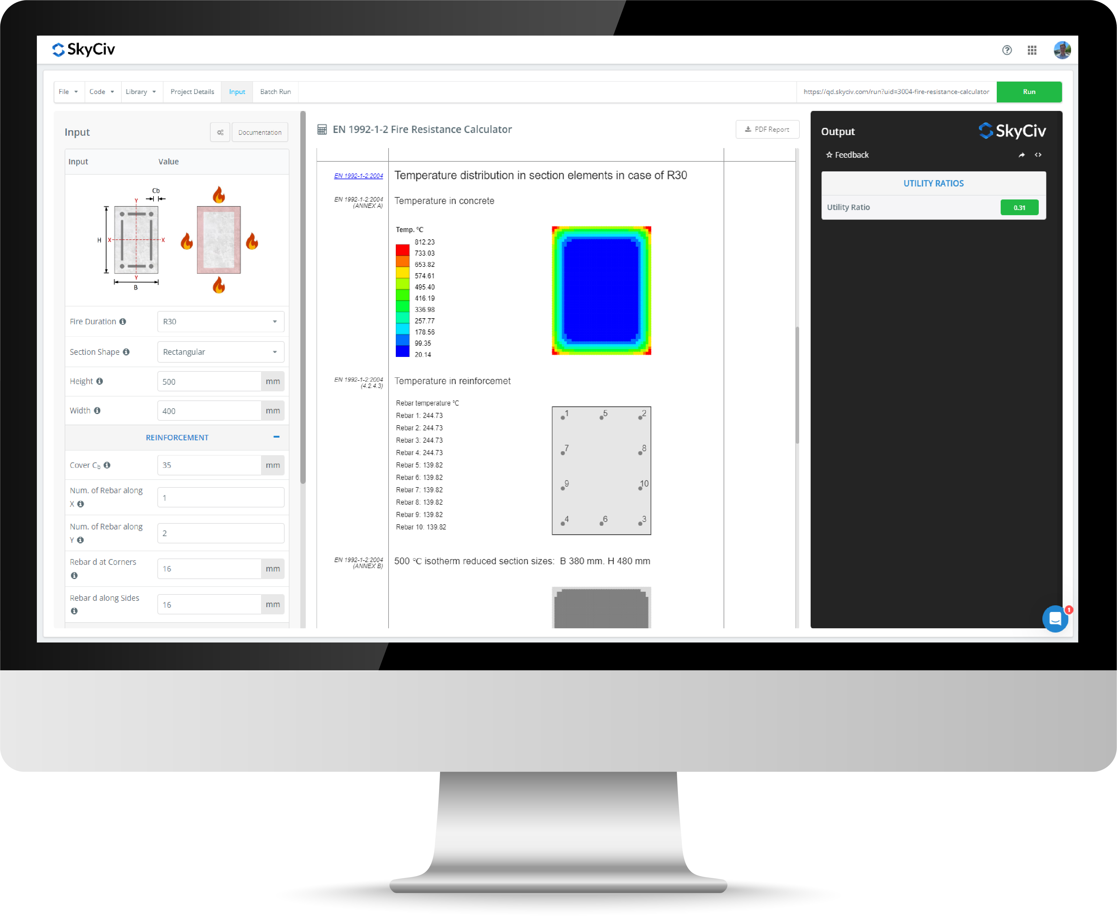
Υπολογιστής χωρητικότητας ικριωμάτων
Ο υπολογιστής σχεδιασμού μελών του SkyCiv Quick Design Design επιτρέπει στους μηχανικούς να σχεδιάζουν ικριώματα στα πρότυπα AISC 360-16, BS EN 12811-1:2003, και AS / NZS 1576. Ο υπολογιστής χωρητικότητας βάρους ικριώματος παρέχει πολλαπλές δυνατότητες σχεδιασμού τόσο για τους σωλήνες ικριώματος όσο και για τους σφιγκτήρες. Το εργαλείο σχεδίασης παρέχει αποτελέσματα χρήσης ικριωμάτων που υπολογίζονται και περιγράφονται λεπτομερώς σε μια επαγγελματική έκθεση, επιτρέποντας στους μηχανικούς να επαληθεύουν κάθε αποτέλεσμα και να κατανοούν τα βήματα υπολογισμού πίσω από αυτά. Χρησιμοποιώντας το εικονίδιο σημαίας στο επάνω αριστερό μέρος της αριθμομηχανής , τα ακόλουθα πρότυπα είναι διαθέσιμα στο λογισμικό σχεδιασμού ικριωμάτων μας:
- Ηνωμένες Πολιτείες - AISC 360-16.
- Αυστραλιανά πρότυπα - AS / NZS 1576 Γενικές Απαιτήσεις Σκαλωσιάς.
- Ευρώπη/Ηνωμένο Βασίλειο - BS EN 12811-1:2003 Εξοπλισμός Προσωρινών Εργασιών - Σκαλωσιές.
Ο υπολογιστής χωρητικότητας φορτίου ικριώματος απαιτεί τη γεωμετρία και το υλικό του μέλους ικριώματος, τα δεδομένα του συζεύκτη, τα φορτία του σχεδιασμού (κάμψη, κουρεύω, αξονική και στρέψη) καθώς και τους αποτελεσματικούς παράγοντες μήκους. Η αριθμομηχανή μπορεί να βοηθήσει τους μηχανικούς να υπολογίσουν τη χωρητικότητα φορτίου ικριώματος για αποτελέσματα, συμπεριλαμβανομένης της αξονικής συμπίεσης, διατμητική ικανότητα και ικανότητα ροπής. Η αριθμομηχανή υποστηρίζει πολλούς τύπους ζεύξεων, συμπεριλαμβανομένων των συζευκτών ορθής γωνίας, παράλληλοι ζεύκτες, περιστρεφόμενοι ζεύκτες και μανίκια τύπου τριβής.
Σχετικά με τον αριθμομηχανή χωρητικότητας φορτίου ικριώματος
Τι είναι το σκαλωσιά του σωλήνα και του σφιγκτήρα?
Το σκαλωσιά του σωλήνα και του σφιγκτήρα είναι ένας κοινός τύπος συστήματος ικριωμάτων που αποτελείται από σωλήνες και σφιγκτήρες από χάλυβα ή αλουμινίου (επίσης γνωστοί ως ζεύκτες ή εξαρτήματα) Για να συνδέσετε τους σωλήνες μαζί. Τα ικριώματα σωλήνων και ζεύκτη είναι κοινά στον κλάδο των κατασκευών όπου απαιτούνται φθηνές και αξιόπιστες προσωρινές δομές για τη διευκόλυνση της αποτελεσματικής κατασκευής.
Τι είναι ένας σφιγκτήρας ικριώματος?
Στο ικρίωμα ενός ζεύκτη αναφέρεται σε ένα εξάρτημα που χρησιμοποιείται για τη σύνδεση δύο μελών ικριωμάτων. Οι ζεύκτες διατίθενται σε διαφορετικούς τύπους και επιλογές.
Οι σφιγκτήρες δεξιάς γωνίας χρησιμοποιούνται για τη σύνδεση οριζόντιων και κατακόρυφων σωλήνων ικριωμάτων και περιστρεφόμενων σφιγκτήρων χρησιμοποιούνται για τη σύνδεση της στήριξης με τη δομή. Οι σφιγκτήρες από άκρο σε άκρο, όπως οι ζεύξεις μανικιών ή οι ζεύκτες αρθρώσεων, μπορούν να χρησιμοποιηθούν για την επέκταση μιας ευθείας εκτέλεσης ικριώματος. Μια βύθιση (Γνωρίστε επίσης ως ρυθμιζόμενο πόδι) Μπορεί να χρησιμοποιηθεί ως βάση εκκίνησης για ικριώματα με ρυθμιζόμενο ύψος για να εξασφαλιστεί ότι το ικριωμένο επίπεδο μπορεί να επιτευχθεί ακόμη και σε ανομοιογενείς επιφάνειες.
Ο τυπικός σωλήνας ικριώματος έχει ένα 48.3 χιλ (1.900 ίντσα) εξωτερική διάμετρο (ΤΟΥ) Και οι περισσότεροι σφιγκτήρες έχουν σχεδιαστεί για αυτό το πρότυπο μέγεθος.
Ποιοι ζεύκτες είναι διαθέσιμοι στον υπολογιστή χωρητικότητας ικριωμάτων?
Στον αριθμομηχανή χωρητικότητας βάρους ικριώματος, οι συνδέσεις που περιλαμβάνονται εξαρτώνται από το πρότυπο σχεδιασμού που αναφέρεται και τι περιλαμβάνεται στις διατάξεις αυτού του προτύπου σχεδιασμού.
Το BS ΕΝ 12811-1:2003 Το παράρτημα C δίνει χαρακτηριστικές τιμές των αντιστάσεων για τους ακόλουθους ζεύξεις:
- Ζεύκτης δεξιάς γωνίας
- Σύνδεσμος μανικιού τύπου τριβής
- Περιστρεφόμενος ζεύκτης
- Παράλληλος ζεύκτης
Αυτοί οι ζεύκτες χωρίζονται σε συζεύκτες κατηγορίας Α και κατηγορίας Β με τη χαρακτηριστική δύναμη που δίνεται για καθένα σε σχέση με τους τύπους φορτίου που μπορεί να μεταφέρει. Ένας μερικός συντελεστής ασφαλείας του 1.5 Χρησιμοποιείται στη συνέχεια για να ληφθεί υπόψη η μεταβλητότητα της δράσης φόρτωσης και ο μερικός συντελεστής ασφαλείας του 1.1 χρησιμοποιείται για μεταβλητότητα αντίστασης. Για παράδειγμα, Ένας ζεύκτης δεξιάς γωνίας κατηγορίας Α έχει χαρακτηριστική αντίσταση ολίσθησης του 10.0 ΚΝ. Μπορούμε στη συνέχεια να προσδιορίσουμε ένα όριο φορτίου εργασίας 10 / (1.1 * 1.5) = 6.1 kn για τους δεξιόστρους της κατηγορίας Α που αντιστέκονται σε μια δύναμη ολίσθησης.
Το AS/NZS 1576.2 (Σύνδεσμοι και αξεσουάρ) Δίνει καθοδήγηση σχετικά με τα ελάχιστα κριτήρια δοκιμών για τους ακόλουθους συζεύκτες:
- Ζεύκτης δεξιάς γωνίας
- Περιστρεφόμενος ζεύκτης
- Σύνδεσμοι από άκρο σε άκρο (δηλ. Σύνδεσμοι μανικιού τύπου τριβής)
- Παράλληλος ζεύκτης
- Ζεύκτης putlog
- Λεπίδα
- Έλεγχος συζεύκτη
- Ρυθμιζόμενο πόδι / Ρυθμιζόμενη πλάκα βάσης / Ρυθμιζόμενη πλάκα περιστροφής
- Φλάντζα
- Καστορί
- Ρυθμιζόμενος καστορέλαιο
Για να ληφθεί το όριο φορτίου εργασίας (Wll) Οι ελάχιστες δυνάμεις δοκιμών που απαιτούνται για να περάσουν το πρότυπο θα πρέπει να μειωθούν με παράγοντα ασφάλειας. Ταυτός AS / NZS 1576.2 δεν καθορίζει ρητά την ασφάλεια του παράγοντα εκτός από τα ρυθμιζόμενα πόδια / Βασικές πλάκες στις οποίες ένας παράγοντας ασφάλειας του 2.5 χρησιμοποιείται και για δεξιόστροφοι ζεύξεις και περιστρεφόμενους ζεύγους για αντίσταση ολίσθησης στον οποίο ένας παράγοντας ασφάλειας του 2 χρησιμοποιείται. Έχουμε εξετάσει έναν παράγοντα ασφάλειας του 2.0 για όλους τους ζεύκτες εκτός από βάσεις που γενικά δίνουν παρόμοια όρια φορτίου εργασίας στο BS EN 12811-1:2003. Για παράδειγμα, ένας δεξιός ζευγάρι έχει μια δοκιμαστική δύναμη ολίσθησης 12.5 ΚΝ. Μπορούμε στη συνέχεια να προσδιορίσουμε ένα ελάχιστο όριο φορτίου εργασίας 12.5/2 = 6.25 kN για δεξιόστροφοι συζεύκτες που αντιστέκονται σε μια δύναμη ολίσθησης.
Όπου ένας κατασκευαστής δοκιμάζει πέρα από τις απαιτήσεις του προτύπου, μπορούν να επιτύχουν υψηλότερο όριο φορτίου εργασίας για το προϊόν τους. Για απλότητα αναφέρθηκε απλώς στις ελάχιστες απαιτήσεις του προτύπου. Όταν χρησιμοποιείτε το Το λογισμικό σχεδιασμού ικριωμάτων SkyCIV που χρησιμοποιεί τη προσαρμοσμένη σύνδεση μπορεί να επιτρέψει σε έναν χρήστη να καθορίσει συγκεκριμένα όρια φορτίου εργασίας που παρέχεται από έναν κατασκευαστή για σύνδεση.
Συζεύκτη ορθής γωνίας
Οι δεξιόστροφοι ζεύγοι συνδέουν σωλήνες ικριώματος σε ακριβώς μια γωνία 90 μοιρών (εξ ου και το όνομα) Δημιουργία σταθερών αρθρώσεων. Οι δεξιόστροφοι συνδέοντες χρησιμοποιούνται συνήθως για τη σύνδεση των κάθετων και οριζόντιων μελών ικριωμάτων.
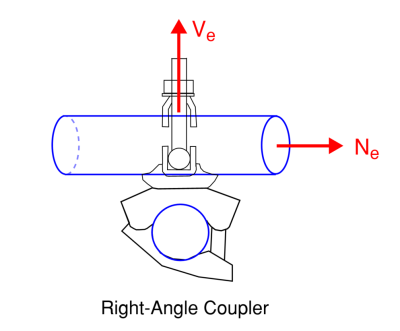
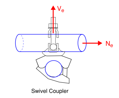
Περιστρεφόμενος ζεύκτης
Ο περιστρεφόμενος ζεύκτης είναι παρόμοιος με τον δεξιό γωνιακό ζευγάρι, ωστόσο, επιτρέπει την περιστροφή και όχι το σταθερό 90 κοινό βαθμός. Αυτό επιτρέπει στους σωλήνες ικριώματος να περιστρέφονται ανεξάρτητα όταν απαιτείται και μπορούν να χρησιμοποιηθούν για τη σύνδεση στοιχείων στήριξης ή μη ομαλοποιημένων ρυθμίσεων εντός της δομής ικριώματος.
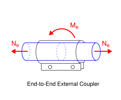
Συνδεδεμένοι με τερματισμό
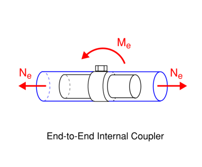
Οι σύνδεσμοι End to End συμμετέχουν σε δύο μέλη ικριωμάτων σε ευθεία γραμμή. Αυτά μπορούν να τοποθετηθούν εξωτερικά στον σωλήνα ικριώματος (Σύνδεσμοι μανικιού τύπου τριβής, Σύνδεσμοι εξωτερικού μανικιού) ή εσωτερικά στον σωλήνα ικριωμάτων (Επέκταση των ζεύκλων αρθρώσεων). Αυτές οι συνδέσεις επιτρέπουν τη μεταφορά στιγμών μεταξύ των μελών και τη μεταφορά δυνάμεων συμπίεσης, ωστόσο δεν παρέχουν αντίσταση σε ένταση. Όπου απαιτείται μεταφορά έντασης, πρέπει να χρησιμοποιείται μια διάταξη.
Η επέκταση των συνδέσμων με καρφίτσες λειτουργούν με την τοποθέτηση μέσα στο ικρίωμα και στη συνέχεια την επέκταση του Flush στο εσωτερικό του σωλήνα ικριώματος.
Οι ζεύξεις με μανίκια κάθονται έξω από τους σωλήνες ικριώματος και σφίγγονται για να ξεπλένονται στο εξωτερικό του σωλήνα ικριώματος.
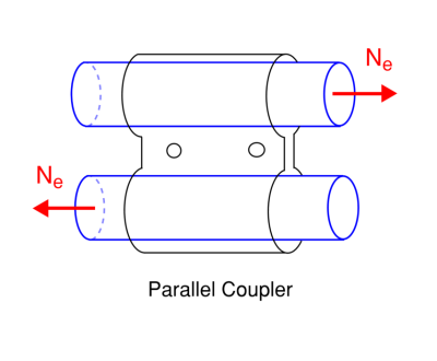
Παράλληλος ζεύκτης
Ο παράλληλος ζεύκτης χρησιμοποιείται για τη δημιουργία σύνδεσης ματίσματος ή σύνδεσης LAP μεταξύ σωλήνων ικριώματος συνδέοντάς τα παράλληλα. Αυτός ο τύπος σύνδεσης μπορεί να χρησιμοποιηθεί για τη μεταφορά αξονικών δυνάμεων μεταξύ των μελών ικριωμάτων.
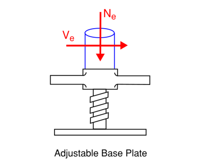
Βίδα
Μια βύθιση βιδών έχει ένα νήμα που επιτρέπει μια ρυθμιζόμενη βάση για την υποστήριξη κάθετων μελών ικριωμάτων στη βάση της δομής ικριωμάτων. Ρυθμίζοντας τη βύθιση, Τα ικριώματα επιπέδου μπορούν να ανεγερθούν από την ομάδα κατασκευής ακόμη και σε ανομοιόμορφες επιφάνειες. Στη συνέχεια, η βιδωτή υποδοχή υποστηρίζει τη δομή ικριώματος μεταφέροντας τις δυνάμεις συμπίεσης και διάτμησης στο ίδρυμα.
Χωρητικότητα φορτίου ικριώματος
Ο τυπικός σωλήνας ικριώματος έχει ένα 48.3 χιλ (1.900 ίντσα) εξωτερική διάμετρο. Δεδομένου ότι υπάρχουν μόνο λίγα πάχη τμήματος και βαθμοί χάλυβα που κατασκευάζονται, υπάρχουν μόνο μερικές διαφορετικές δυνατότητες φορτίου ικριώματος. Δεδομένου ότι είναι δύσκολο να προσδιοριστούν οπτικά το πάχος του τμήματος και ο βαθμός ενός σωλήνα ικριώματος στο χώρο, συνιστάται γενικά να είναι συντηρητικός και να χρησιμοποιεί το λεπτότερο και το χαμηλότερο τμήμα που θα ήταν διαθέσιμο στο χώρο των υπολογισμών σχεδιασμού.
Όταν ο σωλήνας ικριώματος αντιστέκεται μόνο στις δυνάμεις τάσης:
Ντ = Ατ * φάκαι * φ
όπου:
- ΕΝΑτ είναι η περιοχή του σωλήνα ικριώματος
- φάκαι είναι η ισχύς απόδοσης του σωλήνα ικριώματος
- φ είναι ένας παράγοντας ασφαλείας μείωσης της αντοχής
Παράδειγμα χωρητικότητας φορτίου ικριώματος
Για ένα 250 MPA απόδοση ισχύος 48,3x3,2 mm CHS Η χωρητικότητα σύμφωνα με το αυστραλιανό πρότυπο είναι:
Ντ = Ατ * φάκαι * φ
Ντ = 453.4 χιλ2 * 250 MPa * 0.9 = 102.01 ΚΝ
Πίνακες χωρητικότητας φορτίου ικριώματος
Άλλες δυνάμεις έντασης μπορούν να ληφθούν από τον πίνακα χωρητικότητας φορτίου ικριώματος παρακάτω. Οι τιμές έχουν υιοθετηθεί με βάση τον τύπο χωρητικότητας φορτίου ικριώματος για τα σχετικά πρότυπα σχεδιασμού.
| Πρότυπο σχεδίασης | Ενότητα | Σχεδιασμός αντοχή έντασης |
|---|---|---|
| ΣΤΟ | 48.3x3.2 (Βαθμός 250) | 102.01 |
| ΜΟΥ | 48.3x3.2 (Βαθμός 250) | 96.86 |
| ΜΑΣ | 1.900x0.120 (Βαθμός Α53) | 88.2 (19.82 δέρμα μόσχου ακατέργαστου) |
Ο τύπος χωρητικότητας φορτίου ικριώματος για ένα μέλος συμπίεσης είναι διαφορετικός, αφού το μέλος μπορεί να λυγίσει λόγω των δυνάμεων συμπιεστικής. Μπορούμε να υπολογίσουμε την χωρητικότητα βάρους ικριώματος για διαφορετικά αποτελεσματικά μήκη για τα μέλη της συμπίεσης που χρησιμοποιούν τον αριθμομηχανή γρήγορου σχεδιασμού και μια παρτίδα.
| Πρότυπο σχεδίασης | Ενότητα | Ο (Μ) | |||||
| 0 | 1 | 2 | 3 | 4 | 5 | ||
| ΣΤΟ | 48.3x3.2 (Βαθμός 250) | 102.01 ΚΝ | 86.67 ΚΝ | 44.2 ΚΝ | 21.26 ΚΝ | 12.24 ΚΝ | 7.93 ΚΝ |
| ΜΟΥ | 48.3x3.2 (Βαθμός 250) | 96.86 ΚΝ | 72.23 ΚΝ | 36.38 ΚΝ | 19.04 ΚΝ | 11.44 ΚΝ | 7.6 ΚΝ |
Μπορούμε επίσης να κατασκευάσουμε έναν πίνακα για τυπικό μέγεθος ικριώματος που χρησιμοποιείται στις ΗΠΑ για διαφορετικές διαστάσεις για να αποκτήσουμε περισσότερα παραδείγματα χωρητικότητας φορτίου ικριώματος.
| Πρότυπο | Μέγεθος | Ο (πόδια) | ||||
| 3 | 6 | 9 | 12 | 15 | ||
| ΜΑΣ | 1.900x0.120 (A53) | 16.8 δέρμα μόσχου ακατέργαστου | 10.23 δέρμα μόσχου ακατέργαστου | 4.89 δέρμα μόσχου ακατέργαστου | 2.75 δέρμα μόσχου ακατέργαστου | 1.76 δέρμα μόσχου ακατέργαστου |
Ποιες παράμετροι αποτελεσματικού μήκους χρησιμοποιούνται στον υπολογιστή χωρητικότητας ικριώματος?
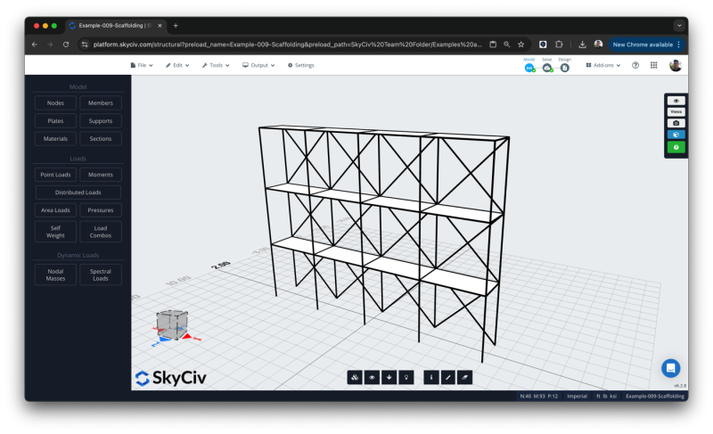
Τα τμήματα στρογγυλών HSS ή CHS δεν είναι ευαίσθητα στον πλευρικό λυγισμό (λυγισμός κάτω από κάμψη) Ωστόσο, μπορούν να λυγίσουν λόγω συμπιεστικών δυνάμεων. ο Το λογισμικό σχεδιασμού ικριωμάτων SkyCIV λαμβάνει μια εισροή για τον αποτελεσματικό παράγοντα μήκους που χρησιμοποιείται στους υπολογισμούς λυγισμού. Όπου χρησιμοποιείται η ενσωμάτωση SkyCIV S3D για το λογισμικό ικριωμάτων, οι παράγοντες αποτελεσματικού μήκους μπορούν να δημιουργηθούν αυτόματα με βάση τους περιορισμούς των μελών στο μοντέλο.
Μια ολοκληρωμένη έκδοση του αριθμομηχανή για το SkyCIV S3D είναι διαθέσιμη για την εισαγωγή όλων των επιλέξιμων μελών στη μονάδα σχεδιασμού ικριωμάτων και την εκτέλεση όλων των ελέγχων χωρητικότητας φορτίου ικριώματος ταυτόχρονα. Η ενσωμάτωση μπορεί να καθορίσει αυτόματα τους κατάλληλους αποτελεσματικούς παράγοντες μήκους με βάση τους περιορισμούς των μελών στο μοντέλο. Μπορείτε να μάθετε περισσότερα σχετικά με τη χρήση της ενσωμάτωσης στο Το Tutorial Design Scaffolding στο SkyCiv S3D.
Ποια φορτία πρέπει να λαμβάνονται υπόψη για τις σκαλωσιές?
Οι μηχανικοί που εργάζονται σε συστήματα σκαλωσιάς θα πρέπει να τα σχεδιάσουν ώστε να αντέχουν σε διάφορους τύπους φορτίων, αυτά τα φορτία περιλαμβάνουν:
- Νεκρά φορτία γενικά από το βάρος του ίδιου του συστήματος σκαλωσιάς.
- Ζωντανά φορτία γενικά από εργάτες και εξοπλισμό που χρησιμοποιείται στις σκαλωσιές.
- Φορτία ανέμου εξαρτώνται από τις τοπικές συνθήκες και πρότυπα.
- Φορτία χιονιού όπου ισχύει και ανάλογα με τις τοπικές συνθήκες και πρότυπα.
- Σεισμικά Φορτία σε περιοχές επιρρεπείς σε σεισμούς και ανάλογα με τις τοπικές συνθήκες και πρότυπα.
Αφού καθοριστούν τα φορτία από εξειδικευμένο δομικό μηχανικό, μπορούν να εφαρμοστούν στο τμήμα φορτίου σχεδιασμού της αριθμομηχανής με τη μορφή κάμψης, κουρεύω, και αξονική δύναμη.
Πώς λειτουργεί μια βιδωτή βύθιση ικριώματος?
Μια βύθιση βιδών μπορεί να αντισταθεί στη συμπίεση και οι δυνάμεις διάτμησης που μεταφέρονται μέσω ικριώματος και στη συνέχεια μπορεί να μεταφέρει τις δυνάμεις στο έδαφος. Μια πλάκα βάσης χρησιμοποιείται για την εξάπλωση των δυνάμεων συμπίεσης σε μια μεγαλύτερη περιοχή εδράνου και μια μοναδική σανίδα τοποθετείται συνήθως στη βάση για να κερδίσει πρόσθετη επιφάνεια ρουλεμάν και ως εκ τούτου αύξηση της χωρητικότητας εδράνου. Οι βάσεις έχουν συχνά τρύπες για άγκυρες που μπορούν να εγκατασταθούν σε ένα σκυρόδεμα που να τείνει ή να θεμελιώνται για να βοηθήσουν να αντισταθούν στις δυνάμεις της διάτμησης και να αποτρέψουν την ολίσθηση της βάσης ικριώματος.
Το ευρωπαϊκό πρότυπο ικριωμάτων έχει πρόβλεψη για το σχεδιασμό βιδών που βρίσκονται στο παράρτημα Β.
Το αυστραλιανό πρότυπο ως 1576.2 Ενότητα 4.3 Συζητά το ελάχιστο όριο φορτίου εργασίας για ρυθμιζόμενες βίδες με βύθιση από χάλυβα και αλουμίνιο.
Συχνές ερωτήσεις
Τι σύστημα μονάδας υποστηρίζεται?
Διατίθενται τόσο μετρικά όσο και αυτοκρατορικά συστήματα μονάδων. Για να αλλάξετε συστήματα μονάδων, κάντε κλικ στο γρανάζι στο επάνω αριστερό μέρος του πίνακα εισόδου.
Ποιες ιδιότητες υλικού λαμβάνονται υπόψη?
Τα εργαλεία σχεδιασμού σκαλωσιάς επιτρέπουν στους χρήστες να εισάγουν τις ακόλουθες ιδιότητες υλικού:
- Μέτρο ελαστικότητας
- Modulus Of Rigidity
- Όριο συμπίεσης λεπτότητας
- Ισχύς απόδοσης μέλους
- Η απόλυτη δύναμη του μέλους
Ποιοι κωδικοί σχεδίασης υποστηρίζονται?
Το λογισμικό σχεδιασμού ικριωμάτων υποστηρίζει το σχεδιασμό σκαλωσιάς σύμφωνα με τα ακόλουθα πρότυπα:
- AISC 360-16 Λογισμικό σχεδιασμού ικριωμάτων.
- AS / NZS 1576 Λογισμικό σχεδιασμού ικριωμάτων.
- BS EN 12811-1:2003 Λογισμικό σχεδιασμού ικριωμάτων.
Αυτές οι επιλογές είναι προσβάσιμες μέσω του εικονιδίου σημαίας στο επάνω μέρος του αριστερού πλαισίου εισόδου για αλλαγή του προτύπου σχεδίασης.
Ποια ανάλυση χρησιμοποιείται για τον υπολογισμό της αντίστασης των συζευκτών?
Η ενότητα σχεδιασμού σκαλωσιάς αποτελείται από την αξιολόγηση των χωρητικοτήτων του συζεύκτη με βάση τη γραμμική στατική ανάλυση των μελών. Για την ευρωπαϊκή έκδοση του σχεδιασμού ελέγξτε τις χωρητικότητες του συζεύκτη όπως δίνονται στο Παράρτημα Γ του ΕΝ 12811.1 χρησιμοποιούνται σε συνδυασμό με τους απαιτούμενους μερικούς παράγοντες ασφάλειας. Για τις απαιτήσεις δοκιμών ζεύξης της Αυστραλίας εκδοχής δίδονται ως ως AS 1576.2 Και αυτές οι τιμές χρησιμοποιούνται για τον προσδιορισμό του ελάχιστου ορίου φορτίου λειτουργίας της τοποθέτησης.
Είναι σκαλωσιά με υποδοχές βάσης που υποστηρίζονται?
Η ευρωπαϊκή και αυστραλιανή έκδοση του εργαλείου υποστηρίζει ικριώματα με βάσης βάσης. Η αμερικανική έκδοση του εργαλείου δεν υποστηρίζει επί του παρόντος το σχεδιασμό ικριώματος με βάσης βάσης.
Σχετικά Εργαλεία
Σχετικά με το SkyCiv
Το SkyCiv προσφέρει ένα ευρύ φάσμα λογισμικού ανάλυσης και σχεδιασμού Cloud Structural για μηχανικούς. Ως μια συνεχώς εξελισσόμενη εταιρεία τεχνολογίας, δεσμευόμαστε να καινοτομούμε και να προκαλούμε υπάρχουσες ροές εργασίας για να εξοικονομήσουμε χρόνο στους μηχανικούς στις διαδικασίες εργασίας και τα σχέδιά τους.

