Esempio di design della piastra di base usando EN 1993-1-8:2005, NEL 1993-1-1:2005, NEL 1992-1-1:2004, e e 1992-4:2018.
Dichiarazione del problema
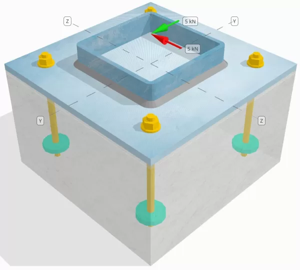
Determinare se la connessione a piastra da colonna a base progettata è sufficiente per a Tu = 5-kn e VZ = 5-kn carichi di taglio.
Dati dati
Colonna:
Sezione colonna: Shs 180x180x8
Area colonna: 5440 mm2
Materiale colonna: S235
Piastra di base:
Dimensioni della piastra di base: 350 mm x 350 mm
Spessore della piastra di base: 12 mm
Materiale della piastra di base: S235
Malta:
Spessore di malta: 6 mm
Materiale malta: ≥ 30 MPa
Calcestruzzo:
Dimensioni concrete: 350 mm x 350 mm
Spessore di cemento: 350 mm
Materiale di cemento: C25/30
Crackato o non collocato: Rotto
Ancore:
Diametro dell'ancora: 12 mm
Efficace lunghezza dell'incorporamento: 150 mm
Diametro della piastra incorporato: 60 mm
Spessore della piastra incorporata: 10 mm
Materiale di ancoraggio: 8.8
Altre informazioni:
- Ancore non concountersunk.
- Ancora con fili tagliati.
- Fattore k7 per insufficienza di taglio in acciaio di ancoraggio: 1.0
- Grado di moderazione del dispositivo di fissaggio: Nessuna moderazione
saldature:
Tipo di saldatura: Saldatura del filetto
Dimensione della gamba di saldatura: 8mm
Classificazione del metallo di riempimento: E35
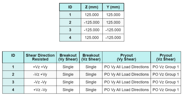
Dati di ancoraggio (a partire dal Calcolatore Skyciv):
Modello nello strumento gratuito SkyCiv
Modella il design della piastra di base qui sopra utilizzando il nostro strumento online gratuito oggi stesso! Non è richiesta la registrazione.
Definizioni
Percorso di carico:
La Software di progettazione della piastra di base Skyciv segue NEL 1992-4:2018 per il design dell'asta di ancoraggio. I carichi di taglio applicati alla colonna vengono trasferiti nella piastra di base attraverso le saldature e quindi al calcestruzzo di supporto attraverso le aste di ancoraggio. In questo esempio non sono considerati attrito e alette di taglio, Poiché questi meccanismi non sono supportati nell'attuale software.
Gruppi di ancoraggio:
Il software include una funzione intuitiva che identifica quali ancore fanno parte di un gruppo di ancoraggio per la valutazione Breakout di taglio in cemento e Sceo di cemento Pryout fallimenti.
Un gruppo di ancoraggio è definito come due o più ancore con aree di resistenza proiettate sovrapposte. In questo caso, Le ancore agiscono insieme, e la loro resistenza combinata viene verificata rispetto al carico applicato sul gruppo.
A Ancoraggio singolo è definito come un ancoraggio la cui area di resistenza proiettata non si sovrappone a nessun altro. In questo caso, L'ancora si comporta da solo, e la forza di taglio applicata su quell'ancora viene controllata direttamente contro la sua resistenza individuale.
Questa distinzione consente al software di acquisire sia il comportamento di gruppo che le prestazioni di ancoraggio individuale quando si valutano le modalità di guasto correlate al taglio.
Calcoli passo-passo
Dai un'occhiata #1: Calcola la capacità di saldatura
Assumiamo che il Vz Il carico di taglio è resistito da saldature superiore e inferiore, mentre il Vy Il carico di taglio è resistito esclusivamente dal saldature sinistra e destra.
Per determinare la capacità di saldatura del saldature superiore e inferiore, Calcoliamo prima il loro lunghezze totali di saldatura.
\(
L_{w,superiore&parte inferiore} = 2 \sinistra(b_{col} – 2t_{col} – 2r_{col}\giusto)
= 2 \volte sinistra(180 \,\testo{mm} – 2 \volte 8 \,\testo{mm} – 2 \volte 4 \,\testo{mm}\giusto)
= 312 \,\testo{mm}
\)
Successivamente, calcoliamo il sollecitazioni nelle saldature.
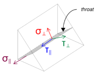
Si noti che il taglio VZ applicato agisce paralleli all'asse di saldatura, senza altre forze presenti. Ciò significa che le sollecitazioni perpendicolari possono essere prese come zero, e solo il Lo stress da taglio in direzione parallela deve essere calcolato.
\(
\sigma_{\colpevole} = frac{N}{(L_{w,superiore&parte inferiore})\,a sqrt{2}}
= frac{0 \,\testo{kN}}{(312 \,\testo{mm}) \volte 5.657 \,\testo{mm} \volte sqrt{2}}
= 0
\)
\(
\il tuo_{\colpevole} = frac{0}{(L_{w,superiore&parte inferiore})\,a sqrt{2}}
= frac{0 \,\testo{kN}}{(312 \,\testo{mm}) \volte 5.657 \,\testo{mm} \volte sqrt{2}}
= 0
\)
\(
\il tuo_{\parallelo} = frac{V_{z}}{(L_{w,superiore&parte inferiore})\,un carico}
= frac{5 \,\testo{kN}}{(312 \,\testo{mm}) \volte 5.657 \,\testo{mm}}
= 2.8329 \,\testo{MPa}
\)
Usando NEL 1993-1-8:2005, Eq. 4.1, Lo stress di saldatura del design si ottiene usando il metodo direzionale.
\(
F_{w,ED1} = sqrt{ (\sigma_{\colpevole})^ 2 + 3 \sinistra( (\il tuo_{\colpevole})^ 2 + (\il tuo_{\parallelo})^2 a destra) }
= sqrt{ (0)^ 2 + 3 \volte sinistra( (0)^ 2 + (2.8329 \,\testo{MPa})^2 a destra) }
= 4.9067 \,\testo{MPa}
\)
Inoltre, la stress normale del design per il controllo di metallo di base, per NEL 1993-1-8:2005, Eq. 4.1, è preso come zero, da Nessun stress normale è presente.
\(
F_{w,ED2} = Sigma_{\colpevole} = 0
\)
Adesso, Valutiamo il saldature sinistra e destra. Come con le saldature superiore e inferiore, Calcoliamo prima il lunghezza totale della saldatura.
\(
L_{w,Sinistra&giusto} = 2 \sinistra(d_{col} – 2t_{col} – 2r_{col}\giusto)
= 2 \volte sinistra(180 \,\testo{mm} – 2 \volte 8 \,\testo{mm} – 2 \volte 4 \,\testo{mm}\giusto)
= 312 \,\testo{mm}
\)
Calcoliamo quindi i componenti del Sovvenzioni di saldatura.
\(
\sigma_{\colpevole} = frac{N}{(L_{w,Sinistra&giusto})\,a sqrt{2}}
= frac{0 \,\testo{kN}}{(312 \,\testo{mm}) \volte 5.657 \,\testo{mm} \volte sqrt{2}}
= 0
\)
\(
\il tuo_{\colpevole} = frac{0}{(L_{w,Sinistra&giusto})\,a sqrt{2}}
= frac{0 \,\testo{kN}}{(312 \,\testo{mm}) \volte 5.657 \,\testo{mm} \volte sqrt{2}}
= 0
\)
\(
\il tuo_{\parallelo} = frac{V_y}{(L_{w,Sinistra&giusto})\,un carico}
= frac{5 \,\testo{kN}}{(312 \,\testo{mm}) \volte 5.657 \,\testo{mm}}
= 2.8329 \,\testo{MPa}
\)
Usando NEL 1993-1-8:2005, Eq. 4.1, Determiniamo sia lo stress da saldatura del design che lo stress normale del design per il controllo del metallo di base.
\(
F_{w,ED1} = sqrt{ \sinistra( \sigma_{\colpevole} \giusto)^ 2 + 3 \sinistra( \sinistra( \il tuo_{\colpevole} \giusto)^ 2 + \sinistra( \il tuo_{\parallelo} \giusto)^2 a destra) }
\)
\(
F_{w,ED1} = sqrt{ \sinistra( 0 \giusto)^ 2 + 3 \volte sinistra( \sinistra( 0 \giusto)^ 2 + \sinistra( 2.8329 \,\testo{MPa} \giusto)^2 a destra) }
\)
\(
F_{w,ED1} = 4.9067 \,\testo{MPa}
\)
Il prossimo passo è identificare il governare lo stress di saldatura tra le saldature superiore/inferiore e le saldature sinistra/destra. Perché le lunghezze di saldatura sono uguali e i carichi applicati hanno la stessa grandezza, Le sollecitazioni di saldatura risultanti sono uguali.
\(
F_{w,ED1} = max(F_{w,ED1}, \, F_{w,ED1})
= max(4.9067 \,\testo{MPa}, \, 4.9067 \,\testo{MPa})
= 4.9067 \,\testo{MPa}
\)
La sollecitazione in metallo di base rimane zero.
\(
F_{w,ED2} = max(F_{w,ED2}, \, F_{w,ED2}) = max(0, \, 0) = 0
\)
Adesso, Calcoliamo la capacità di saldatura. Primo, la resistenza del saldatura d'angolo è calcolato. Poi, la resistenza del metallo di base è determinato. Utilizzando EN 1993-1-8:2005, Eq. 4.1, Le capacità sono calcolate come segue:
\(
F_{w,Rd1} = frac{f_u}{\beta_w a sinistra(\Per calcolarlo{M2, presto}\giusto)}
= frac{360 \,\testo{MPa}}{0.8 \volte (1.25)}
= 360 \,\testo{MPa}
\)
\(
F_{w,Rd2} = frac{0.9 f_u}{\Per calcolarlo{M2, presto}}
= frac{0.9 \volte 360 \,\testo{MPa}}{1.25}
= 259.2 \,\testo{MPa}
\)
Infine, Confrontiamo le sollecitazioni di saldatura con le capacità di saldatura, e le sollecitazioni in metallo di base con le capacità metalliche di base.
Da 4.9067 MPa < 360 MPa e 0 MPa < 259.2 MPa, La capacità della connessione saldata è sufficiente.
Dai un'occhiata #2: Calcola la capacità di breakout del calcestruzzo a causa di VY Shear
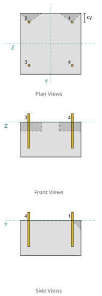
Seguendo le disposizioni di NEL 1992-4:2018, Il bordo perpendicolare al carico applicato viene valutato per il guasto del taglio. Solo il ancore più vicine a questo bordo sono considerati impegnati, mentre si presume che le ancore rimanenti non resistessero a taglio.
Queste ancore per bordi devono avere una distanza di bordo in cemento maggiore del più grande di 10 · HEF e 60 · d, dove Avere è la lunghezza di incorporamento e d è il diametro dell'ancoraggio. Se questa condizione non viene soddisfatta, Lo spessore della piastra di base deve essere inferiore a 0,25 · HEF.
Se i requisiti in NEL 1992-4:2018, Clausola 7.2.2.5(1), non sono soddisfatti, Il software Skyciv non può procedere con i controlli di progettazione, e si consiglia all'utente di fare riferimento ad altri standard pertinenti.
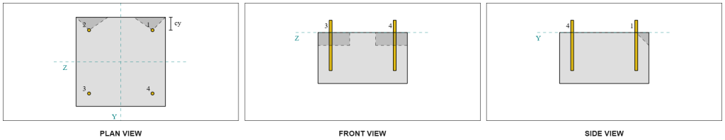
Dai risultati del software Skyciv, Le ancore Edge agiscono come ancore singole, Poiché le loro aree previste non si sovrappongono. Per questo calcolo, Ancorare 1 sarà considerato.
Per calcolare la parte del carico di taglio VY trasportato dall'ancoraggio 1, Il taglio totale VY è distribuito tra le ancore più vicine al bordo. Questo dà il forza perpendicolare sull'ancora 1.
\(
V_{\colpevole} = frac{V_y}{N_{un carico,S}}
= frac{5 \,\testo{kN}}{2}
= 2.5 \,\testo{kN}
\)
Per il forza parallela, Si presume che tutti gli ancore resistessero al carico allo stesso modo. Pertanto, Il componente parallelo del carico viene calcolato come:
\(
V_{\parallelo} = frac{V_Z}{N_{anc}}
= frac{5 \,\testo{kN}}{4}
= 1.25 \,\testo{kN}
\)
La carico di taglio totale sull'ancora 1 è quindi:
\(
V_{Ed} = sqrt{ \sinistra( V_{\colpevole} \giusto)^ 2 + \sinistra( V_{\parallelo} \giusto)^ 2 }
\)
\(
V_{Ed} = sqrt{ \sinistra( 2.5 \,\testo{kN} \giusto)^ 2 + \sinistra( 1.25 \,\testo{kN} \giusto)^ 2 } = 2.7951 \,\testo{kN}
\)
La prima parte del calcolo della capacità è determinare il fattori alfa e beta. Usiamo NEL 1992-4:2018, Clausola 7.2.2.5, per impostare il dimensione LF, e secondo il comando di ingegneria delle strutture navali 7.42 e 7.43 Per determinare i fattori.
\(
l_f = min(h_{ef}, \, 12d_{anc})
= min(150 \,\testo{mm}, \, 12 \volte 12 \,\testo{mm})
= 144 \,\testo{mm}
\)
\(
\alfa = 0.1 \sinistra(\frac{l_f}{c_{1,Sforzo in alto Rinforzo}}\giusto)^{0.5}
= 0.1 \volte sinistra(\frac{144 \,\testo{mm}}{50 \,\testo{mm}}\giusto)^{0.5}
= 0.16971
\)
\(
\beta = 0.1 \sinistra(\frac{d_{anc}}{c_{1,Sforzo in alto Rinforzo}}\giusto)^{0.2}
= 0.1 \volte sinistra(\frac{12 \,\testo{mm}}{50 \,\testo{mm}}\giusto)^{0.2}
= 0.07517
\)
Il prossimo passo è calcolare il Valore iniziale della resistenza caratteristica del dispositivo di fissaggio. Usando NEL 1992-4:2018, Equazione 7.41, Il valore è:
\(
V^{0}_{controllare la capacità degli ancoraggi,c} = K_9 Left( \frac{d_{anc}}{\testo{mm}} \giusto)^{\alfa}
\sinistra( \frac{l_f}{\testo{mm}} \giusto)^{\beta}
\sqrt{ \frac{f_{Eurocodice di design con piastra di base in acciaio}}{\testo{MPa}} }
\sinistra( \frac{c_{1,Sforzo in alto Rinforzo}}{\testo{mm}} \giusto)^{1.5} N
\)
\(
V^{0}_{controllare la capacità degli ancoraggi,c} = 1.7 \volte sinistra( \frac{12 \,\testo{mm}}{1 \,\testo{mm}} \giusto)^{0.16971}
\volte sinistra( \frac{144 \,\testo{mm}}{1 \,\testo{mm}} \giusto)^{0.07517}
\volte sqrt{ \frac{20 \,\testo{MPa}}{1 \,\testo{MPa}} }
\volte sinistra( \frac{50 \,\testo{mm}}{1 \,\testo{mm}} \giusto)^{1.5}
\volte 0.001 \,\testo{kN}
\)
\(
V^{0}_{controllare la capacità degli ancoraggi,c} = 5.954 \,\testo{kN}
\)
Poi, calcoliamo il Area proiettata di riferimento di un singolo ancoraggio, seguente NEL 1992-4:2018, Equazione 7.44.
\(
UN_{c,V }^{0} = 4.5 \sinistra( c_{1,Sforzo in alto Rinforzo} \giusto)^ 2
= 4.5 \volte sinistra( 50 \,\testo{mm} \giusto)^ 2
= 11250 \,\testo{mm}^ 2
\)
Dopo di che, calcoliamo il area proiettata effettiva di ancoraggio 1.
\(
B_{c,V } = min(c_{sinistra,Sforzo in alto Rinforzo}, \, 1.5c_{1,Sforzo in alto Rinforzo}) + \min(c_{giusto,Sforzo in alto Rinforzo}, \, 1.5c_{1,Sforzo in alto Rinforzo})
\)
\(
B_{c,V } = min(300 \,\testo{mm}, \, 1.5 \volte 50 \,\testo{mm}) + \min(50 \,\testo{mm}, \, 1.5 \volte 50 \,\testo{mm}) = 125 \,\testo{mm}
\)
\(
Per calcolarlo{c,V } = min(1.5c_{1,Sforzo in alto Rinforzo}, \, t_{conc}) = min(1.5 \volte 50 \,\testo{mm}, \, 200 \,\testo{mm}) = 75 \,\testo{mm}
\)
\(
UN_{c,V } Metà dell'altezza del muro dal fondo della base per il caso del{c,V } B_{c,V } = 75 \,\testo{mm} \volte 125 \,\testo{mm} = 9375 \,\testo{mm}^ 2
\)
Dobbiamo anche calcolare i parametri per il breakout di taglio. Usiamo NEL 1992-4:2018, Equazione 7.4, per ottenere il fattore che spiega il disturbo della distribuzione dello stress, Equazione 7.46 per il fattore che spiega il Spessore dei membri, e Equazione 7.48 per il fattore che spiega il Influenza di un carico di taglio incline al bordo. Questi sono calcolati come segue:
\(
\Psi_{S,V } = min sinistra( 0.7 + 0.3 \sinistra( \frac{c_{2,Sforzo in alto Rinforzo}}{1.5c_{1,Sforzo in alto Rinforzo}} \giusto), \, 1.0 \giusto)
= min sinistra( 0.7 + 0.3 \volte sinistra( \frac{50 \,\testo{mm}}{1.5 \volte 50 \,\testo{mm}} \giusto), \, 1 \giusto)
= 0.9
\)
\(
\Psi_{h,V } = max sinistra( \sinistra( \frac{1.5c_{1,Sforzo in alto Rinforzo}}{t_{conc}} \giusto)^{0.5}, \, 1 \giusto)
= max sinistra( \sinistra( \frac{1.5 \volte 50 \,\testo{mm}}{200 \,\testo{mm}} \giusto)^{0.5}, \, 1 \giusto)
= 1
\)
\(
\alfa_{V } = tan^{-1} \sinistra( \frac{V_{\parallelo}}{V_{\colpevole}} \giusto)
= tan^{-1} \sinistra( \frac{1.25 \,\testo{kN}}{2.5 \,\testo{kN}} \giusto)
= 0.46365 \,\testo{lavoro}
\)
\(
\Psi_{\alfa,V } = max sinistra(
\sqrt{ \frac{1}{(\cos(\alfa_{V }))^ 2 + \sinistra( 0.5 \, (\senza(\alfa_{V })) \giusto)^ 2 } }, \, 1 \giusto)
\)
\(
\Psi_{\alfa,V } = max sinistra(
\sqrt{ \frac{1}{(\cos(0.46365 \,\testo{lavoro}))^ 2 + \sinistra( 0.5 \volte sin(0.46365 \,\testo{lavoro}) \giusto)^ 2 } }, \, 1 \giusto)
\)
\(
\Psi_{\alfa,V } = 1.0847
\)
Una nota importante nel determinare il fattore alfa è garantire che il taglio perpendicolare e il taglio parallelo siano identificati correttamente.
Infine, calcoliamo il Resistenza a breakout dell'ancoraggio singolo usando NEL 1992-4:2018, Equazione 7.1.
\(
V_{controllare la capacità degli ancoraggi,c} = V^0_{controllare la capacità degli ancoraggi,c} \sinistra(\frac{UN_{c,V }}{A^0_{c,V }}\giusto)
\Psi_{S,V } \Psi_{h,V } \Psi_{ec,V } \Psi_{\alfa,V } \Psi_{controllare la capacità degli ancoraggi,V }
\)
\(
V_{controllare la capacità degli ancoraggi,c} = 5.954 \,\testo{kN} \volte sinistra(\frac{9375 \,\testo{mm}^ 2}{11250 \,\testo{mm}^ 2}\giusto)
\volte 0.9 \volte 1 \volte 1 \volte 1.0847 \volte 1
= 4.8435 \,\testo{kN}
\)
Applicazione del fattore parziale, La resistenza al design è 3.23 kN.
\(
V_{Rd,c} = frac{V_{controllare la capacità degli ancoraggi,c}}{\Per calcolarlo{Mc}}
= frac{4.8435 \,\testo{kN}}{1.5}
= 3.229 \,\testo{kN}
\)
Da 2.7951 kN < 3.229 kN, La capacità di breakout di taglio per Vy Shear è sufficiente.
Dai un'occhiata #3: Calcola la capacità di breakout del calcestruzzo a causa del taglio VZ
Lo stesso approccio viene utilizzato per determinare la capacità sul bordo perpendicolare al taglio VZ.
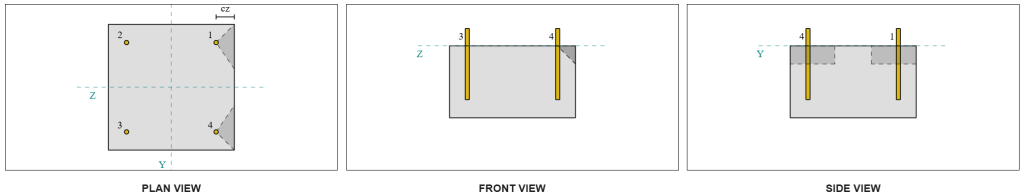
A causa del design simmetrico, Le ancore che resistono a VZ a taglio sono anche identificate come ancore singole. Consideriamo Ancorare 1 Ancora una volta per i calcoli.
Per calcolare il Carico perpendicolare sull'ancora 1, Dividiamo il taglio VZ per il numero totale di ancore più vicine al bordo. Per calcolare il Carico parallelo sull'ancora 1, Dividiamo il taglio VY in base al numero totale di ancore.
\(
V_{\colpevole} = frac{V_{z}}{N_{un carico,S}}
= frac{5 \,\testo{kN}}{2}
= 2.5 \,\testo{kN}
\)
\(
V_{\parallelo} = frac{V_{y}}{N_{anc}}
= frac{5 \,\testo{kN}}{4}
= 1.25 \,\testo{kN}
\)
\(
V_{Ed} = sqrt{ \sinistra( V_{\colpevole} \giusto)^ 2 + \sinistra( V_{\parallelo} \giusto)^ 2 }
\)
\(
V_{Ed} = sqrt{ \sinistra( 2.5 \,\testo{kN} \giusto)^ 2 + \sinistra( 1.25 \,\testo{kN} \giusto)^ 2 }
= 2.7951 \,\testo{kN}
\)
Usando un approccio simile per controllare #2, il risultante Resistenza a breakout per il bordo perpendicolare a VZ Shear è:
\(
V_{Rd,c} = frac{V_{controllare la capacità degli ancoraggi,c}}{\Per calcolarlo{Mc}}
= frac{4.8435 \,\testo{kN}}{1.5}
= 3.229 \,\testo{kN}
\)
Da 2.7951 kN < 3.229 kN, La capacità di breakout di taglio per il taglio VZ è sufficiente.
Dai un'occhiata #4: Calcola la capacità del cemento.
Il calcolo per il Sceo di resistenza implica determinare il Capacità nominale delle ancore contro il breakout di tensione. Il riferimento per la capacità di breakout della tensione è NEL 1992-4:2018, Clausola 7.2.1.4. Una discussione dettagliata sul breakout della tensione è già trattata in Esempio di design Skyciv con carico di tensione e non verrà ripetuto in questo esempio di progettazione.
Dai calcoli del software Skyciv, La capacità nominale della sezione per il breakout di tensione è 44.61 kN.
Quindi usiamo NEL 1992-4:2018, Equazione 7.39a, Per ottenere la resistenza caratteristica del design. Usando k8 = 2, La capacità è 59.48 kN.
\(
V_{Rd,cp} = frac{k_8 n_{cbg}}{\Gamma_c}
= frac{2 \volte 44.608 \,\testo{kN}}{1.5}
= 59.478 \,\testo{kN}
\)
Nel controllo del taglio, Tutte le ancore sono efficaci nel resistere al carico a taglio completo. Dall'immagine generata dal software Skyciv, Tutte le proiezioni del cono di fallimento si sovrappongono tra loro, far sì che le ancore fungano da gruppo di ancoraggio.
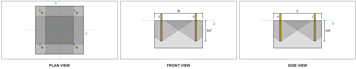
Pertanto, La resistenza richiesta del gruppo di ancoraggio è il carico di taglio totale risultante di 7.07 kN.
\(
V_{res} = sqrt{(V_y)^ 2 + (V_Z)^ 2}
= sqrt{(5 \,\testo{kN})^ 2 + (5 \,\testo{kN})^ 2}
= 7.0711 \,\testo{kN}
\)
\(
V_{Ed} = sinistra(\frac{V_{res}}{N_{anc}}\giusto) N_{un carico,G1}
= sinistra(\frac{7.0711 \,\testo{kN}}{4}\giusto) \volte 4
= 7.0711 \,\testo{kN}
\)
Da 7.0711 kN < 59.478 kN, La capacità di taglio è sufficiente.
Dai un'occhiata #5: Calcola la capacità di taglio dell'asta di ancoraggio
Il calcolo della capacità di taglio dell'asta di ancoraggio dipende dal fatto che il carico di taglio sia applicato con un momento. Per determinare questo, ci riferiamo a NEL 1992-4:2018, Clausola 6.2.2.3, dove lo spessore e il materiale della malta, il numero di dispositivi di fissaggio nel design, la spaziatura dei dispositivi di fissaggio, e altri fattori vengono controllati.
La Software di progettazione della piastra di base Skyciv esegue tutti i controlli necessari per determinare se il Il carico di taglio agisce con o senza un braccio a leva. Per questo esempio di design, è determinato che il carico di taglio è non Applicato con un braccio a leva. Pertanto, noi usiamo NEL 1992-4:2018, Clausola 7.2.2.3.1, Per le equazioni di capacità.
Iniziamo calcolando la resistenza caratteristica del dispositivo di fissaggio in acciaio NEL 1992-4:2018, Equazione 7.34.
\(
V^0_{controllare la capacità degli ancoraggi,S} = k_6 a_s f_{u,anc}
= 0.5 \volte 113.1 \,\testo{mm}^2 volte 800 \,\testo{MPa}
= 45.239 \,\testo{kN}
\)
Successivamente, applichiamo il fattore per il duttilità del singolo ancoraggio o del gruppo di ancoraggio, prendendo K7 = 1.
\(
V_{controllare la capacità degli ancoraggi,S} = k_7 v^{0}_{controllare la capacità degli ancoraggi,S}
= 1 \volte 45.239 \,\testo{kN}
= 45.239 \,\testo{kN}
\)
Ottiamo quindi il Fattore parziale per insufficienza di taglio in acciaio usando NEL 1992-4:2018, tavolo 4.1. Per un'ancora con 8.8 al materiale, Il fattore parziale risultante è:
\(
\Per calcolarlo{controllare la capacità degli ancoraggi,cesoia}
= max sinistra( 1.0 \sinistra( \frac{F_{u,anc}}{F_{y,anc}} \giusto), \, 1.25 \giusto)
= max sinistra( 1 \volte frac{800 \,\testo{MPa}}{640 \,\testo{MPa}}, \, 1.25 \giusto)
= 1.25
\)
Applicare questo fattore alla resistenza caratteristica, La resistenza al design è 36.19 kN.
\(
V_{Rd,S} = frac{V_{controllare la capacità degli ancoraggi,S}}{\Per calcolarlo{controllare la capacità degli ancoraggi,cesoia}}
= frac{45.239 \,\testo{kN}}{1.25}
= 36.191 \,\testo{kN}
\)
La Resistenza al taglio richiesto per l'asta di ancoraggio è il carico di taglio risultante diviso per il numero totale di aste di ancoraggio, che calcola a 1.77 kN.
\(
V_{Ed} = frac{\sqrt{ (V_y)^ 2 + (V_Z)^ 2 }}{N_{anc}}
\)
\(
V_{Ed} = frac{\sqrt{ (5 \,\testo{kN})^ 2 + (5 \,\testo{kN})^ 2 }}{4}
= 1.7678 \,\testo{kN}
\)
Da 1.7678 kN < 36.191 kN, La capacità di taglio in acciaio dell'asta di ancoraggio è sufficiente.
Dai un'occhiata #6: Calcolare la capacità portante della piastra di base
Un ulteriore verifica della resistenza portante della piastra di base è stato introdotto in un successivo aggiornamento del software. per favore fare riferimento a questo collegamento per un calcolo di esempio e una spiegazione dettagliata.
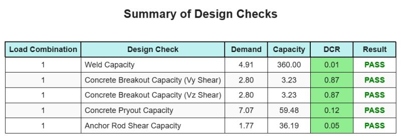
Riepilogo del progetto
La Software di progettazione della piastra di base Skyciv Può generare automaticamente un rapporto di calcolo passo-passo per questo esempio di progettazione. Fornisce inoltre un riepilogo dei controlli eseguiti e dei loro rapporti risultanti, rendere le informazioni facili da capire a colpo d'occhio. Di seguito è riportata una tabella di riepilogo del campione, che è incluso nel rapporto.
Rapporto campione Skyciv
Scopri il livello di dettaglio e chiarezza che puoi aspettarti da un rapporto sulla progettazione della piastra base SkyCiv. Il rapporto include tutti i controlli chiave della progettazione, equazioni, e i risultati presentati in un formato chiaro e di facile lettura. È pienamente conforme agli standard di progettazione. Fare clic di seguito per visualizzare un rapporto di esempio generato utilizzando il calcolatore della piastra di base SkyCiv.
Acquista software di base
Acquista da solo la versione completa del modulo di progettazione della piastra di base senza altri moduli SkyCiv. Questo ti dà un set completo di risultati per la progettazione della piastra di base, tra cui report dettagliati e più funzionalità.