Esempio di design della piastra di base usando CSA S16:19 e CSA A23.3:19
Dichiarazione del problema
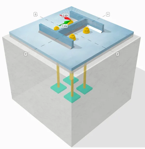
Determinare se la connessione a piastra da colonna a base progettata è sufficiente per a Tu = 5-kn e VZ = 5-kn carichi di taglio.
Dati dati
Colonna:
Sezione colonna: HP200x54
Area colonna: 6840.0 mm2
Materiale colonna: 350W
Piastra di base:
Dimensioni della piastra di base: 400 mm x 400 mm
Spessore della piastra di base: 13 mm
Materiale della piastra di base: 300W
Malta:
Spessore della malta: 13 mm
Calcestruzzo:
Dimensioni concrete: 450 mm x 450 mm
Spessore di cemento: 380 mm
Materiale di cemento: 20.68 MPa
Crackato o non collocato: Rotto
Ancore:
Diametro dell'ancora: 12.7 mm
Efficace lunghezza dell'incorporamento: 300 mm
Spessore della rondella della piastra: 0 mm
Attacco rondella piastra: No
saldature:
Dimensione della saldatura: 8 mm
Classificazione del metallo di riempimento: E43xx
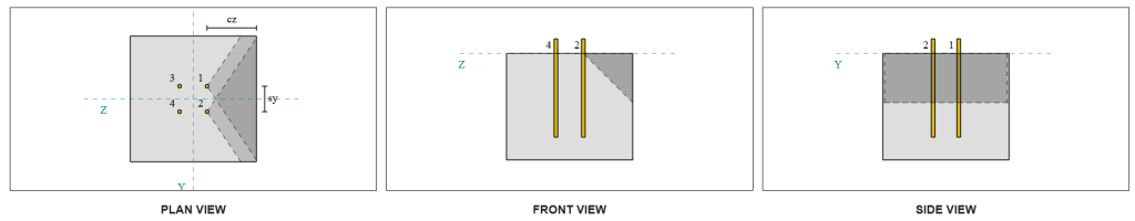
Dati di ancoraggio (a partire dal Calcolatore Skyciv):
Modello nello strumento gratuito SkyCiv
Modella il design della piastra di base qui sopra utilizzando il nostro strumento online gratuito oggi stesso! Non è richiesta la registrazione.
Definizioni
Percorso di carico:
Il design segue il CSA A23.3:2019 standard e le raccomandazioni di Guida alla progettazione AISC 1, 3Rd Edition. I carichi di taglio applicati alla colonna vengono trasferiti alla piastra di base attraverso le saldature, e poi al calcestruzzo portante attraverso il aste di ancoraggio. In questo esempio non sono considerati attrito e alette di taglio, Poiché questi meccanismi non sono supportati nell'attuale software.
Per impostazione predefinita, il il carico di taglio applicato è distribuito su tutti gli ancoraggi, sia attraverso l'uso di rondelle saldate che con altri mezzi tecnici. Il carico trasportato da ciascun ancoraggio viene determinato utilizzando i tre (3) casi indicati in CSA A23.3:2019 Clausola D.7.2.1 e Figura D.13. Ciascun ancoraggio trasferisce quindi il carico al calcestruzzo di supporto sottostante. La distribuzione del carico secondo questi riferimenti viene utilizzata anche durante la verifica della resistenza a taglio dell'acciaio dell'ancorante per garantire la continuità nelle ipotesi di trasferimento del carico.
Come alternativa, il software consente un'ipotesi semplificata e più conservativa, dove il l'intero carico di taglio è assegnato solo agli ancoranti più vicini al bordo caricato. In questo caso, la verifica della capacità di taglio viene effettuata solo su questi ancoraggi di bordo, garantire che la potenziale rottura a taglio sia affrontata in modo conservativo.
Gruppi di ancoraggio:
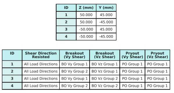
La Software di progettazione della piastra di base Skyciv Include una caratteristica intuitiva che identifica quali ancore fanno parte di un gruppo di ancoraggio per la valutazione Breakout di taglio in cemento e Sceo di cemento Pryout fallimenti.
Un gruppo di ancoraggio è definito come due o più ancore con aree di resistenza proiettate sovrapposte. In questo caso, Le ancore agiscono insieme, e la loro resistenza combinata viene verificata rispetto al carico applicato sul gruppo.
A Ancoraggio singolo è definito come un ancoraggio la cui area di resistenza proiettata non si sovrappone a nessun altro. In questo caso, L'ancora si comporta da solo, e la forza di taglio applicata su quell'ancora viene controllata direttamente contro la sua resistenza individuale.
Questa distinzione consente al software di acquisire sia il comportamento di gruppo che le prestazioni di ancoraggio individuale quando si valutano le modalità di guasto correlate al taglio.
Calcoli passo-passo
Dai un'occhiata #1: Calcola la capacità di saldatura
Il primo passo è calcolare il lunghezza totale della saldatura disponibile per resistere al taglio. La lunghezza totale della saldatura, Lweld , si ottiene sommando le saldature su tutti i lati.
\( L_{saldare} = 2b_f + 2(d_{col} – 2t_f – 2r_{col}) + 2(b_f – t_w – 2r_{col}) \)
\( L_{saldare} = 2 \volte 207,testo{mm} + 2 \volte (204,\testo{mm} – 2 \volte 11.3,testo{mm} – 2 \volte 9,7,testo{mm}) + 2 \volte (207,\testo{mm} – 11.3,\testo{mm} – 2 \volte 9,7,testo{mm}) = 1090,6,testo{mm} \)
Utilizzando questa lunghezza di saldatura, le forze di taglio applicate in y- e le direzioni z vengono divise per determinare la media forza di taglio per unità di lunghezza in ogni direzione:
\( v_{fy} = frac{V_y}{L_{saldare}} = frac{5,\testo{kN}}{1090.6,\testo{mm}} = 0.0045846,testo{metri ed è fissato alla base e fissato in alto} \)
\( v_{fz} = frac{V_Z}{L_{saldare}} = frac{5,\testo{kN}}{1090.6,\testo{mm}} = 0.0045846,testo{metri ed è fissato alla base e fissato in alto} \)
La domanda di taglio risultante per unità di lunghezza viene quindi determinata utilizzando la radice quadrata della somma dei quadrati (SRSS) metodo.
\( v_f = sqrt{\sinistra((v_{fy})^2destra) + \sinistra((v_{fz})^2destra)} \)
\( v_f = sqrt{\sinistra((0.0045846,\testo{metri ed è fissato alla base e fissato in alto})^2destra) + \sinistra((0.0045846,\testo{metri ed è fissato alla base e fissato in alto})^2destra)} = 0.0064836,testo{metri ed è fissato alla base e fissato in alto} \)
Successivamente, la capacità di saldatura viene calcolata utilizzando CSA S16:19 Clausola 13.13.2.2, con il coefficiente di forza direzionale preso come kds=1.0 per essere conservativi. La capacità di saldatura per una saldatura di 8 mm sia sulle flange che sull'anima è:
\( v_r = 0,67phi t_{w,flangia}X_u = 0.67 \volte 0.67 \volte 5.657,testo{mm} \volte 430,testo{MPa} = 1.092,testo{metri ed è fissato alla base e fissato in alto} \)
\( v_r = 0,67phi t_{w,ragnatela}X_u = 0.67 \volte 0.67 \volte 5.657,testo{mm} \volte 430,testo{MPa} = 1.092,testo{metri ed è fissato alla base e fissato in alto} \)
Il governare capacità di saldatura d'angolo è:
\( v_{r,filetto} = min(v_r, v_i) = min(1.092\,\testo{metri ed è fissato alla base e fissato in alto}, 1.092\,\testo{metri ed è fissato alla base e fissato in alto}) = 1.092,testo{metri ed è fissato alla base e fissato in alto} \)
Per questa connessione saldata, la forza dell'elettrodo non sovrascrive i punti di forza dei metalli di base. Pertanto, il controllo del metallo base non è determinante e non necessita di essere eseguito.
Da 0.0064 metri ed è fissato alla base e fissato in alto < 1.092 metri ed è fissato alla base e fissato in alto, la capacità di saldatura presa in considerazione è sufficiente.
Dai un'occhiata #2: Calcola la capacità di breakout del calcestruzzo a causa di VY Shear
Capacità del bordo perpendicolare:
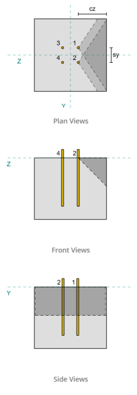
Utilizzando i valori ca1 di ciascun ancoraggio per proiettare i coni di rottura, il software ha identificato che i coni di rottura di questi ancoraggi si sovrappongono. Pertanto, possiamo trattarli come un gruppo di ancoraggio. Riferendosi a CSA A23.3:19 Figura. D.13, perché s<ca1, noi usiamo Astuccio 3 determinare la resistenza del gruppo di ancoraggio alla rottura per taglio. inoltre, il supporto è stato determinato non essere un membro ristretto, quindi la distanza ca1 viene utilizzata direttamente senza modifiche.
Astuccio 3:
La forza totale da considerare per Case 3 è il piena forza di taglio lungo la direzione Vy. Questa forza di taglio viene applicata solo agli ancoraggi anteriori.
\( V_{faperp,caso3} = V_y = 5,testo{kN} \)
Per calcolare la capacità del gruppo di ancoraggio, noi usiamo CSA A23.3:19 Clausola D.7.2. La area massima proiettata per un singolo ancoraggio viene calcolato utilizzando Equazione D.34 con l'attuale cadimensione.
\( UN_{VCo} = 4.5(c_{a1, g1})^2 = 4.5 \volte (180\,\testo{mm})^2 = 145800,testo{mm}^ 2 \)
Per ottenere l'area proiettata effettiva del gruppo di ancoraggio, Determiniamo prima il larghezza della superficie di rottura:
\( B_{Vc} = min(c_{\testo{sinistra},G1}, 1.5c_{a1, g1}) + (\min(S_{\testo{somma},x,G1}, 3c_{a1, g1}(N_{x,G1} – 1))) + \min(c_{\testo{giusto},G1}, 1.5c_{a1, g1}) \)
\( B_{Vc} = min(175\,\testo{mm}, 1.5 \volte 180,testo{mm}) + (\min(100\,\testo{mm}, 3 \volte 180,testo{mm} \volte (2-1))) + \min(175\,\testo{mm}, 1.5 \volte 180,testo{mm}) \)
\( B_{Vc} = 450,testo{mm} \)
La altezza della superficie di rottura è:
\( Per calcolarlo{Vc} = min(1.5c_{a1, g1}, t_{\testo{conc}}) = min(1.5 \volte 180,testo{mm}, 380\,\testo{mm}) = 270,testo{mm} \)
Questo dà il superficie totale come:
\( UN_{Vc} = B_{Vc}.Per calcolarlo{Vc} = 450,testo{mm} \volte 270,testo{mm} = 121500,testo{mm}^ 2 \)
Quindi usiamo CSA A23.3:19 Equazioni D.35 e D.36 per ottenere la resistenza alla rottura di base del singolo ancorante.
\( V_{br1} = 0,58sinistra(\frac{\min(l_e, 8d_a)}{d_a}\giusto)^{0.2}\sqrt{\frac{d_a}{mm}}\philambda_asqrt{\frac{f'_c}{MPa}}\sinistra(\frac{c_{a1, g1}}{mm}\giusto)^{1.5}R(N) \)
\( V_{br1} = 0.58 \volte sinistra(\frac{\min(300\,\testo{mm}, 8 \volte 12,7,testo{mm})}{12.7\,\testo{mm}}\giusto)^{0.2} \volte sqrt{\frac{12.7\,\testo{mm}}{1\,\testo{mm}}} \volte 0.65 \volte 1 \volte sqrt{\frac{20.68\,\testo{MPa}}{1\,\testo{MPa}}} \volte sinistra(\frac{180\,\testo{mm}}{1\,\testo{mm}}\giusto)^{1.5} \volte 1 \volte 0,001,testo{kN} \)
\( V_{br1} = 22.364,testo{kN} \)
\( V_{br2} = 3,75lambda_aphisqrt{\frac{f'_c}{MPa}}\sinistra(\frac{c_{a1, g1}}{mm}\giusto)^{1.5}R(N) \)
\( V_{br2} = 3.75 \volte 1 \volte 0.65 \volte sqrt{\frac{20.68\,\testo{MPa}}{1\,\testo{MPa}}} \volte sinistra(\frac{180\,\testo{mm}}{1\,\testo{mm}}\giusto)^{1.5} \volte 1 \volte 0,001,testo{kN} = 26.769,testo{kN} \)
La capacità di governo tra le due condizioni è:
\( V_{br} = min(V_{\testo{br1}}, V_{\testo{br2}}) = min(22.364\,\testo{kN}, 26.769\,\testo{kN}) = 22.364,testo{kN} \)
Successivamente, calcoliamo il fattore di eccentricità, Fattore di effetto Edge, e il fattore di spessore utilizzando CSA A23.3:19 Clausole D.7.2.5, D.7.2.6, e D.7.2.8.
La fattore di eccentricità è:
\( \Psi_{ec,V } = minsinistra(1.0, \frac{1}{1 + \frac{2e’_N}{3c_{a1, g1}}}\giusto) = minsinistra(1, \frac{1}{1 + \frac{2\volte0}{3\volte180,testo{mm}}}\giusto) = 1 \)
La Fattore di effetto Edge è:
\( \Psi_{ed,V } = minsinistra(1.0, 0.7 + 0.3\sinistra(\frac{c_{a2,g1}}{1.5c_{a1, g1}}\giusto)\giusto) = minsinistra(1, 0.7 + 0.3 \volte sinistra(\frac{175\,\testo{mm}}{1.5 \volte 180,testo{mm}}\giusto)\giusto) = 0.89444 \)
La fattore di spessore è:
\( \Psi_{h,V } = massimosinistra(\sqrt{\frac{1.5c_{a1, g1}}{t_{\testo{conc}}}}, 1.0\giusto) = massimosinistra(\sqrt{\frac{1.5 \volte 180,testo{mm}}{380\,\testo{mm}}}, 1\giusto) = 1 \)
Infine, la forza di rottura del gruppo di ancoraggio, calcolato utilizzando CSA A23.3:19 Clausola D.7.2.1, è:
\( V_{cbgperp} = sinistra(\frac{UN_{Vc}}{UN_{VCo}}\giusto)\Psi_{ec,V }\Psi_{ed,V }\Psi_{c,V }\Psi_{h,V }V_{br} \)
\( V_{cbgperp} = sinistra(\frac{121500\,\testo{mm}^ 2}{145800\,\testo{mm}^ 2}\giusto) \volte 1 \volte 0.89444 \volte 1 \volte 1 \volte 22.364,testo{kN} = 16.669,testo{kN} \)
La capacità calcolata per il taglio Vy nel direzione perpendicolare è 16.669 kN.
Capacità del bordo parallelo:
Fallimento lungo il bordo parallelo al carico è possibile anche in questo scenario, pertanto è necessario determinare la capacità di strappo del calcestruzzo per il bordo parallelo. Gli ancoraggi interessati sono diversi a causa della nuova proiezione del cono di rottura. In base alla figura seguente, il le proiezioni del cono di rottura si sovrappongono; perciò, le ancore vengono nuovamente trattate come un gruppo di ancoraggio.
Astuccio 3:
Il caso da utilizzare è ancora Astuccio 3 da s<ca1. Pertanto, il carico preso da questo gruppo di ancoraggio è il pieno carico di taglio Vy.
\( V_{faperp,caso3} = V_y = 5,testo{kN} \)
Seguiamo quindi gli stessi passaggi per quanto riguarda la capacità perpendicolare.
La superficie di cedimento per un ancoraggio individuale è:
\( UN_{VCo} = 4.5(c_{a1, g1})^2 = 4.5 \volte (175\,\testo{mm})^2 = 137810,testo{mm}^ 2 \)
La superficie di rottura effettiva del gruppo di ancoraggio è:
\( B_{Vc} = min(c_{\testo{parte inferiore},G1}, 1.5c_{a1, g1}) + (\min(S_{\testo{somma},y,G1}, 3c_{a1, g1}(N_{y,G1} – 1))) + \min(c_{\testo{superiore},G1}, 1.5c_{a1, g1}) \)
\( B_{Vc} = min(180\,\testo{mm}, 1.5 \volte 175,testo{mm}) + (\min(90\,\testo{mm}, 3 \volte 175,testo{mm} \volte (2-1))) + \min(180\,\testo{mm}, 1.5 \volte 175,testo{mm}) \)
\( B_{Vc} = 450,testo{mm} \)
\( Per calcolarlo{Vc} = min(1.5c_{a1, g1}, t_{\testo{conc}}) = min(1.5 \volte 175,testo{mm}, 380\,\testo{mm}) = 262,5,testo{mm} \)
\( UN_{Vc} = B_{Vc}Per calcolarlo{Vc} = 450,testo{mm} \volte 262,5,testo{mm} = 118130,testo{mm}^ 2 \)
Allo stesso modo, il rottura di base di un'ancora singola punti di forza sono calcolati come segue:
\( V_{br1} = 0,58sinistra(\frac{\min(l_e, 8d_a)}{d_a}\giusto)^{0.2}\sqrt{\frac{d_a}{mm}}\philambda_asqrt{\frac{f'_c}{MPa}}\sinistra(\frac{c_{a1, g1}}{mm}\giusto)^{1.5}R(N) \)
\( V_{br1} = 0.58 \volte sinistra(\frac{\min(300\,\testo{mm}, 8 \volte 12,7,testo{mm})}{12.7\,\testo{mm}}\giusto)^{0.2} \volte sqrt{\frac{12.7\,\testo{mm}}{1\,\testo{mm}}} \volte 0.65 \volte 1 \volte sqrt{\frac{20.68\,\testo{MPa}}{1\,\testo{MPa}}} \volte sinistra(\frac{175\,\testo{mm}}{1\,\testo{mm}}\giusto)^{1.5} \volte 1 \volte 0,001,testo{kN} \)
\( V_{br1} = 21.438,testo{kN} \)
\( V_{br2} = 3,75lambda_aphisqrt{\frac{f'_c}{MPa}}\sinistra(\frac{c_{a1, g1}}{mm}\giusto)^{1.5}R(N) \)
\( V_{br2} = 3.75 \volte 1 \volte 0.65 \volte sqrt{\frac{20.68\,\testo{MPa}}{1\,\testo{MPa}}} \volte sinistra(\frac{175\,\testo{mm}}{1\,\testo{mm}}\giusto)^{1.5} \volte 1 \volte 0,001,testo{kN} = 25.661,testo{kN} \)
La forza governativa è:
\( V_{br} = min(V_{\testo{br1}}, V_{\testo{br2}}) = min(21.438\,\testo{kN}, 25.661\,\testo{kN}) = 21.438,testo{kN} \)
Calcoliamo quindi il fattore di eccentricità e fattore di spessore:
\( \Psi_{ec,V } = minsinistra(1.0, \frac{1}{1 + \frac{2e’_N}{3c_{a1, g1}}}\giusto) = minsinistra(1, \frac{1}{1 + \frac{2\volte0}{3\volte175,testo{mm}}}\giusto) = 1 \)
\( \Psi_{h,V } = massimosinistra(\sqrt{\frac{1.5c_{a1, g1}}{t_{\testo{conc}}}}, 1.0\giusto) = massimosinistra(\sqrt{\frac{1.5 \volte 175,testo{mm}}{380\,\testo{mm}}}, 1\giusto) = 1 \)
Per il fattore di effetto del bordo di breakout, lo prendiamo come 1.0 per CSA A23.3:19 Clausola D.7.2.1c. Inoltre, si assume il valore della capacità di sfondamento per lo spigolo perpendicolare il doppio del valore calcolato utilizzando l'equazione D.33 (per un gruppo di ancoraggio).
La preso in considerazione capacità di sfondamento del gruppo di ancoraggio è:
\( V_{cbgrparallelo} = 2sinistra(\frac{UN_{Vc}}{UN_{VCo}}\giusto)\Psi_{ec,V }\Psi_{ed,V }\Psi_{c,V }\Psi_{h,V }V_{br} \)
\( V_{cbgrparallelo} = 2 \volte sinistra(\frac{118130\,\testo{mm}^ 2}{137810\,\testo{mm}^ 2}\giusto) \volte 1 \volte 1 \volte 1 \volte 1 \volte 21.438,testo{kN} = 36.752,testo{kN} \)
- Per il bordo perpendicolare fallimento, da 5 kN < 16.7 kN, la capacità di rottura a taglio del calcestruzzo è sufficiente.
- Per il bordo parallelo fallimento, da 5 kN < 36.8 kN, la capacità di rottura a taglio del calcestruzzo è sufficiente.
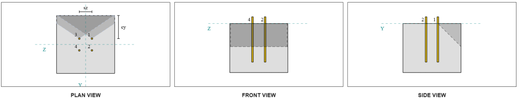
Calcola la capacità di breakout del calcestruzzo a causa del taglio VZ
Anche la piastra di base è sottoposta a taglio Vz, quindi il fallimento è ai margini perpendicolare e parallelo al taglio Vz deve essere controllato. Utilizzando lo stesso approccio, le capacità perpendicolari e parallele vengono calcolate come 16.6 kN e 37.3 kN, rispettivamente.
Bordo perpendicolare:
Bordo parallelo:
Queste capacità vengono poi confrontate con le forze richieste.
- Per il bordo perpendicolare fallimento, da 5 kN < 16.6 kN, la capacità di rottura a taglio del calcestruzzo presa in considerazione è sufficiente.
- Per il rottura del bordo parallelo, da 5 kN < 37.3 kN, la capacità di rottura a taglio del calcestruzzo presa in considerazione è sufficiente.
Dai un'occhiata #4: Calcola la capacità del cemento.
Il cono di cemento per fallimento è lo stesso cono utilizzato nel controllo di rottura a trazione. Per calcolare la capacità di scalzamento a taglio, il resistenza alla rottura a trazione nominale dei singoli ancoraggi o del gruppo di ancoraggi deve essere prima determinato. I calcoli dettagliati per la verifica di rottura per trazione sono già trattati nel Esempi di progettazione SkyCiv per carico di tensione e non verrà ripetuto qui.
È importante notare che la determinazione del gruppo di ancoraggio per la rottura per taglio è diversa da quella per la rottura per taglio. Gli ancoraggi nel progetto devono ancora essere controllati per determinare se sono agire come gruppo o come singole ancore. La classificazione dei supporto come una sezione stretta anch'esso deve essere verificato e deve seguire le stesse condizioni utilizzate per la rottura della tensione.
Secondo il software SkyCiv, la resistenza alla trazione nominale del gruppo di ancoraggio è 60.207 kN. Con un fattore di protezione pari a 2.0, il capacità di presa presa in considerazione è:
\( V_{cpgr} controllare la capacità degli ancoraggi{cp}N_{cbr} = 2 \volte 60.207,testo{kN} = 120.41,testo{kN} \)
La forza richiesta è la risultante dei carichi di taglio applicati. Poiché tutte le ancore appartengono a un unico gruppo, il taglio risultante totale è assegnato al gruppo.
\( V_{fa} = sqrt{((V_y)^ 2) + ((V_Z)^ 2)} = sqrt{((5\,\testo{kN})^ 2) + ((5\,\testo{kN})^ 2)} = 7.0711,testo{kN} \)
\( V_{fa} = sinistra(\frac{V_{fa}}{n / a}\giusto)N_{un carico,G1} = sinistra(\frac{7.0711\,\testo{kN}}{4}\giusto) \volte 4 = 7.0711,testo{kN} \)
Da 7.07 kN < 120.4 kN, la capacità di presa calcolata è sufficiente.
Dai un'occhiata #5: Calcola la capacità di taglio dell'asta di ancoraggio
Ricordiamolo in questo esempio di progettazione, il taglio è distribuito su tutti gli ancoraggi. La carico di taglio totale per ancorante è quindi la risultante della sua quota del carico Vy e della sua quota del carico Vz. Consideriamo anche il caso governativo utilizzati nelle verifiche di rottura a taglio.
Per Vy taglio, Astuccio 3 sta governando.
\( V_{fa,y} = frac{V_y}{N_{z,G1}} = frac{5\,\testo{kN}}{2} = 2,5,testo{kN} \)
Allo stesso modo, per taglio Vz, Astuccio 3 sta governando.
\( V_{fa,z} = frac{V_Z}{N_{y,G1}} = frac{5\,\testo{kN}}{2} = 2,5,testo{kN} \)
Questo dà il forza di taglio sulla barra di ancoraggio come:
\( V_{fa} = sqrt{((V_{fa,y})^ 2) + ((V_{fa,z})^ 2)} = sqrt{((2.5\,\testo{kN})^ 2) + ((2.5\,\testo{kN})^ 2)} = 3.5355,testo{kN} \)
In questo esempio di progettazione, la malta è presente. Pertanto, sperimenta anche la barra di ancoraggio flessione dovuta al taglio eccentrico. Per tenere conto di ciò, possiamo applicare il fattore di riduzione della malta secondo CSA A23.3:19 Clausola D.7.1.3 o verificare l'interazione taglio-flessione utilizzando CSA S16:19 Clausola 13.12.1.4.
Per questo calcolo, abbiamo deciso di utilizzare il 0.8 riduzione fattore da CSA A23.3. Per consentire il giudizio ingegneristico individuale, il Software della piastra base SkyCiv fornisce la possibilità di disabilitare questo fattore di riduzione e utilizzare invece la verifica dell'interazione taglio-flessione. Questa funzionalità può essere esplorata utilizzando il file Strumento gratuito per piastra di base.
CSA A23.3 Capacità di taglio della barra di ancoraggio:
Primo, calcoliamo la capacità di taglio della barra di ancoraggio utilizzando CSA A23.3. La minimo sforzo di trazione dell'asta di ancoraggio è:
\( f_{uta} = min(F_{u _anc}, 1.9F_{il primo}, 860) = min(400\,\testo{MPa}, 1.9 \volte 248,2,testo{MPa}, 860.00\,\testo{MPa}) = 400,testo{MPa} \)
La capacità di taglio della barra di ancoraggio calcolata, calcolato utilizzando CSA A23.3:19 Equazione D.31 e clausola D.7.1.3, è:
\( V_{sar,a23} = 0,8A_{lo so,V }\phi_s0.6f_{uta}R = 0.8 \volte 92,testo{mm}^2 volte 0.85 \volte 0.6 \volte 400,testo{MPa} \volte 0.75 = 11.258,testo{kN} \)
Si noti che il 0.8 qui viene applicato un fattore di riduzione dovuto alla presenza di malta. Questa ridotta capacità di taglio spiega la flessione aggiuntiva della barra di ancoraggio.
Capacità di taglio della barra di ancoraggio CSA S16:
Per la capacità CSA S16, solo il la capacità di taglio è verificatad, poiché la flessione dovuta al taglio eccentrico è già stata presa in considerazione nella verifica CSA A23.3.
La capacità di taglio fattorizzata viene calcolato utilizzando CSA S16:19 Clausola 25.3.3.3.
\( V_{r,s16} = 0,7phi_m 0,6n A_{sr} F_{u _anc} = 0.7 \volte 0.67 \volte 0.6 \volte 1 \volte 126,68,testo{mm}^2 volte 400,testo{MPa} = 14.255,testo{kN} \)
Per garantire che entrambi i metodi siano presi in considerazione, la capacità di governo è assunta come il minore tra i due valori, che è 11.258 kN.
Da 3.54 kN < 11.258 kN, la capacità di taglio calcolata della barra di ancoraggio è sufficiente.
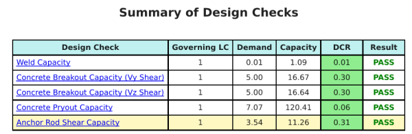
Riepilogo del progetto
La Software di progettazione della piastra di base Skyciv Può generare automaticamente un rapporto di calcolo passo-passo per questo esempio di progettazione. Fornisce inoltre un riepilogo dei controlli eseguiti e dei loro rapporti risultanti, rendere le informazioni facili da capire a colpo d'occhio. Di seguito è riportata una tabella di riepilogo del campione, che è incluso nel rapporto.
Rapporto campione Skyciv
Scopri il livello di dettaglio e chiarezza che puoi aspettarti da un rapporto sulla progettazione della piastra base SkyCiv. Il rapporto include tutti i controlli chiave della progettazione, equazioni, e i risultati presentati in un formato chiaro e di facile lettura. È pienamente conforme agli standard di progettazione. Fare clic di seguito per visualizzare un rapporto di esempio generato utilizzando il calcolatore della piastra di base SkyCiv.
Acquista software di base
Acquista da solo la versione completa del modulo di progettazione della piastra di base senza altri moduli SkyCiv. Questo ti dà un set completo di risultati per la progettazione della piastra di base, tra cui report dettagliati e più funzionalità.