Esempio di design della piastra di base usando EN 1993-1-8-2005, NEL 1993-1-1-2005 e e 1992-1-1-2004
Dichiarazione del problema
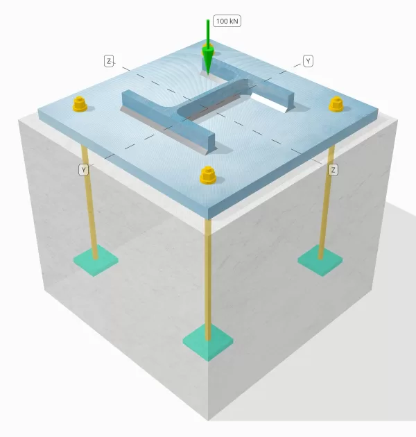
Determina se la connessione a piastra da colonna a base progettata è sufficiente per un carico di compressione da 100 kn.
Dati dati
Colonna:
Sezione colonna: LUI 200 B
Area colonna: 7808 mm2
Materiale colonna: S235
Piastra di base:
Dimensioni della piastra di base: 400 mm x 400 mm
Spessore della piastra di base: 20 mm
Materiale della piastra di base: S235
Malta:
Spessore di malta: 20 mm
Calcestruzzo:
Dimensioni concrete: 450 mm x 450 mm
Spessore di cemento: 380 mm
Materiale di cemento: C20/25
saldature:
Carico di compressione trasferito solo attraverso saldature? NO
Modello nello strumento gratuito SkyCiv
Modella il design della piastra di base qui sopra utilizzando il nostro strumento online gratuito oggi stesso! Non è richiesta la registrazione.
Calcoli passo-passo
Dai un'occhiata #1: Calcola la capacità di saldatura
Poiché il carico di compressione non viene trasferito solo attraverso le saldature, È necessaria una superficie di cuscinetto a contatto adeguata per garantire che il carico venga trasferito tramite cuscinetto. Fare riferimento a NEL 1090-2:2018 Clausola 6.8 per la preparazione del cuscinetto a contatto.
Inoltre, Utilizzare la dimensione minima della saldatura specificato in Eurocode.
Dai un'occhiata #2: Calcola la capacità del cuscinetto in calcestruzzo e la capacità di resa della piastra di base
Il primo passo è determinare la resistenza a compressione del design dell'articolazione, che dipende dalla geometria del supporto (calcestruzzo) e la geometria dell'area caricata (utilizza combinazioni di carico fattorizzate in ASCE).
Iniziamo calcolando il fattore alfa, che spiega la diffusione della forza concentrata all'interno della fondazione.
Secondo NEL 1992-1-1:2004, Clausola 6.7, Il coefficiente alfa è il rapporto tra l'area caricata e l'area di distribuzione massima, che ha una forma simile all'area caricata.
Useremo l'equazione da Parte 6.1 di edifici in acciaio a più piani 5 di Arcelor Mittal, PEINER CORRIER, e Corus per calcolare il fattore alfa.
\(
\alfa = min sinistra(
1 + \frac{t_{\testo{conc}}}{\max(L_{\testo{p.p}}, B_{\testo{p.p}})},
1 + 2 \sinistra( \frac{e_h}{L_{\testo{p.p}}} \giusto),
1 + 2 \sinistra( \frac{e_b}{B_{\testo{p.p}}} \giusto),
3
\giusto)
\)
\(
\alfa = min sinistra(
1 + \frac{380 \, \testo{mm}}{\max(400 \, \testo{mm}, 400 \, \testo{mm})},
1 + 2 \sinistra( \frac{25 \, \testo{mm}}{400 \, \testo{mm}} \giusto),
1 + 2 \sinistra( \frac{25 \, \testo{mm}}{400 \, \testo{mm}} \giusto),
3
\giusto)
\)
\(
\alfa = 1.125
\)
dove,
\(
e_h = frac{L_{\testo{conc}} – L_{\testo{p.p}}}{2} = frac{450 \, \testo{mm} – 400 \, \testo{mm}}{2} = 25 \, \testo{mm}
\)
\(
e_b = frac{B_{\testo{conc}} – B_{\testo{p.p}}}{2} = frac{450 \, \testo{mm} – 400 \, \testo{mm}}{2} = 25 \, \testo{mm}
\)
Una volta definita la geometria, Determineremo quindi la resistenza a compressione del calcestruzzo utilizzando NEL 1992-1-1:2004, Eq. 3.15.
\(
f_{CD} = frac{\alfa_{cc} f_{Eurocodice di design con piastra di base in acciaio}}{\Gamma_c} = frac{1 \volte 20 \, \testo{MPa}}{1.5} = 13.333 \, \testo{MPa}
\)
Successivamente, Assumiamo un valore per il coefficiente beta. Poiché la malta è presente, Il valore beta può essere 2/3. Calcoleremo la resistenza al cuscinetto del design dell'articolazione usando le formule combinate da NEL 1993-1-8:2005 Eq. 6.6, e NEL 1992-1-1:2004 Eq. 6.63.
\(
f_{Eurocodice di design con piastra di base in acciaio} = beta alfa f_{CD} = 0.66667 \volte 1.125 \volte 13.333 \, \testo{MPa} = 10 \, \testo{MPa}
\)
La seconda parte prevede il calcolo della capacità di resa della piastra di base.
Dal momento che abbiamo già la forza del cuscinetto del design della connessione, Lo useremo per determinare la più piccola distanza a sbalzo della piastra di base che sperimenta il carico completo. Ci faremo riferimento al Sci P358 Esempio a pagina 243 e NEL 1993-1-1:2005 Clausola 6.2.5.
\(
c = t_{\testo{p.p}} \sqrt{\frac{f_{y_{\testo{p.p}}}}{3 f_{Eurocodice di design con piastra di base in acciaio} \Per calcolarlo{M0}}} = 20 \, \testo{mm} \volte sqrt{\frac{225 \, \testo{MPa}}{3 \volte 10 \, \testo{MPa} \volte 1}} = 54.772 \, \testo{mm}
\)
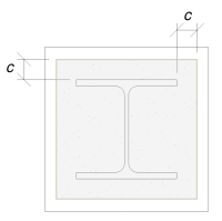
Useremo questa dimensione per calcolare l'area effettiva della piastra di base. Il "c’ La dimensione che abbiamo calcolato può sovrapporsi o non si sovrappone vicino alla flangia. Se si sovrappone, Supponiamo che la sezione sia una sezione rettangolare. Se non si sovrappone, Prenderemo la forma della colonna.
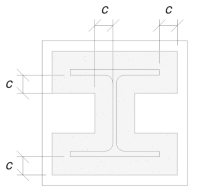
Senza sovrapposizione
Con sovrapposizione
Abbiamo determinato che la "C’ La dimensione non si sovrappone. Pertanto, usando Sci P358 pg. 243, L'area efficace è:
\(
A_e = 4c^2 + Design di piastre di base in acciaio con piccolo momento{\testo{col}}c + UN_{\testo{col}} = 4 \Times 54.772^2 \, \testo{mm}^ 2 + 1182 \, \testo{mm} \volte 54.772 \, \testo{mm} + 7808 \, \testo{mm}^2 = 84549 \, \testo{mm}^ 2
\)
È importante notare che l'area efficace non dovrebbe essere inferiore all'area della piastra di base.
Infine, noi useremo NEL 1993-1-8:2005 Eq. 6.6, e e 1992-1-1:2004, Eq. 6.63 Per calcolare la resistenza al cuscinetto del design della connessione della piastra di base.
\(
N_{Rd} = sinistra( \min(A_e, A_0) \giusto) f_{Eurocodice di design con piastra di base in acciaio} = sinistra( \min(84549 \, \testo{mm}^ 2, 160000 \, \testo{mm}^ 2) \giusto) \volte 10 \, \testo{MPa} = 845.49 \, \testo{kN}
\)
Da 845.49 kN > 100 kN, Il design è sufficiente!
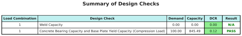
Riepilogo del progetto
Il software di progettazione della piastra di base Skyciv può generare automaticamente un rapporto di calcolo passo-passo per questo esempio di progettazione. Fornisce inoltre un riepilogo dei controlli eseguiti e dei loro rapporti risultanti, rendere le informazioni facili da capire a colpo d'occhio. Di seguito è riportata una tabella di riepilogo del campione, che è incluso nel rapporto.
Rapporto campione Skyciv
Scopri il livello di dettaglio e chiarezza che puoi aspettarti da un rapporto sulla progettazione della piastra base SkyCiv. Il rapporto include tutti i controlli chiave della progettazione, equazioni, e i risultati presentati in un formato chiaro e di facile lettura. È pienamente conforme agli standard di progettazione. Fare clic di seguito per visualizzare un rapporto di esempio generato utilizzando il calcolatore della piastra di base SkyCiv.
Acquista software di base
Acquista da solo la versione completa del modulo di progettazione della piastra di base senza altri moduli SkyCiv. Questo ti dà un set completo di risultati per la progettazione della piastra di base, tra cui report dettagliati e più funzionalità.