Esempio di design della piastra di base usando EN 1993-1-8-2005, NEL 1993-1-1-2005 e e 1992-1-1-2004
Dichiarazione del problema
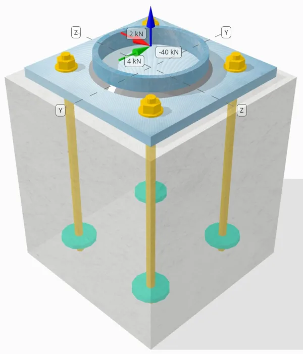
Determinare se la connessione a piastra da colonna a base progettata è sufficiente per a 50-carico di trazione kN, 4-kN Vy carico di taglio, e 2-kN Vz carico di taglio.
Dati dati
Colonna:
Sezione colonna: CHS193.7×10
Area colonna: 5770.0 mm²
Materiale colonna: S460
Piastra di base:
Dimensioni della piastra di base: 300mm x 300 mm
Spessore della piastra di base: 18mm
Materiale della piastra di base: S235
Malta:
Spessore di malta: 0 mm
Calcestruzzo:
Dimensioni concrete: 350mm x 350 mm
Spessore di cemento: 400 mm
Materiale di cemento: C35/45
Crackato o non collocato: Rotto
Ancore:
Diametro dell'ancora: 16 mm
Efficace lunghezza dell'incorporamento: 350 mm
Diametro della piastra incorporato: 70 mm
Spessore della piastra incorporata: 10 mm
Materiale di ancoraggio: 4.8
saldature:
Tipo di saldatura: Filetto
Dimensione della saldatura: 7mm
Classificazione del metallo di riempimento: E42
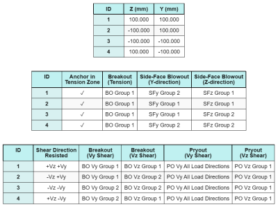
Dati di ancoraggio (a partire dal Calcolatore Skyciv):
Modello nello strumento gratuito SkyCiv
Modella il design della piastra di base qui sopra utilizzando il nostro strumento online gratuito oggi stesso! Non è richiesta la registrazione.
Appunti
Lo scopo di questo esempio di progettazione è quello di dimostrare i calcoli passo-passo per le verifiche di capacità che coinvolgono carichi assiali e di taglio simultanei. Alcuni dei controlli richiesti sono già stati discussi nei precedenti esempi di progettazione. Si prega di fare riferimento ai collegamenti forniti in ciascuna sezione.
Calcoli passo-passo
Dai un'occhiata #1: Calcola la capacità di saldatura
Il pieno carico di trazione è contrastato da intera sezione di saldatura, mentre il componenti del carico di taglio sono distribuiti solo su una parte della lunghezza totale della saldatura. Questa porzione è determinata proiettando a 90° settore dal centro della colonna alla sua circonferenza. Pertanto, solo metà della circonferenza totale è progettato per resistere al carico di taglio.
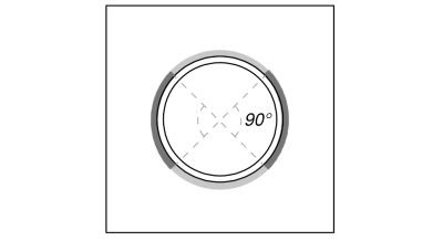
Per prima cosa calcoliamo il lunghezza totale della saldatura che per il porzione della saldatura entro la proiezione di 90°.
\(L_{saldare,pieno} = pi d_{col} = pi volte 193.7\ \testo{mm} = 608.53\ \testo{mm}\)
\(L_{saldare} = frac{\pi d_{col}}{2} = frac{\pi volte 193.7\ \testo{mm}}{2} = 304.26\ \testo{mm}\)
Successivamente, calcoliamo il carico di taglio risultante.
\(V_r = sqrt{(V_y)^ 2 + (V_Z)^ 2} = sqrt{(4\ \testo{kN})^ 2 + (2\ \testo{kN})^ 2} = 4.4721\ \testo{kN}\)
Calcoliamo quindi il normale e sollecitazioni di taglio, tenendo conto della distribuzione del carico ipotizzata.
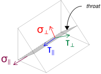
\( \sigma_{\colpevole} = frac{N_x}{L_{saldare,pieno}\,a,sqrt{2}} = frac{40\ \testo{kN}}{608.53\ \testo{mm} \volte 4.95\ \testo{mm} \volte sqrt{2}} = 9.39\ \testo{MPa} \)
\( \il tuo_{\colpevole} = frac{N_x}{L_{saldare,pieno}\,a,sqrt{2}} = frac{40\ \testo{kN}}{608.53\ \testo{mm} \volte 4.95\ \testo{mm} \volte sqrt{2}} = 9.39\ \testo{MPa} \)
\( \il tuo_{\parallelo} = frac{V_r}{L_{saldare}\,un carico} = frac{4.4721\ \testo{kN}}{304.26\ \testo{mm} \volte 4.95\ \testo{mm}} = 2.9693\ \testo{MPa} \)
Dopo di che, calcoliamo il tensioni combinate usando NEL 1993-1-8:2005 Eq. (4.1).
\(F_{w,ED1} = sqrt{(\sigma_{\colpevole})^ 2 + 3\grande((\il tuo_{\colpevole})^ 2 + (\il tuo_{\parallelo})^2grande)}\)
\(F_{w,ED1} = sqrt{(9.39\ \testo{MPa})^ 2 + 3\grande((9.39\ \testo{MPa})^ 2 + (2.9693\ \testo{MPa})^2grande)}\)
\(F_{w,ED1} = 19.471\ \testo{MPa}\)
Allo stesso tempo, Determiniamo il sollecitazione sul metallo base utilizzando la stessa equazione.
\(F_{w,ED2} = Sigma_{\colpevole} = 9.39\ \testo{MPa}\)
Successivamente, calcoliamo il capacità di saldatura. Per prima cosa determiniamo il resistenza alla trazione finale (fu) del materiale più debole, e poi utilizzare NEL 1993-1-8:2005 Eq. (4.1) per ottenere il resistenza della saldatura d'angolo e resistenza dei metalli di base.
\(f_u = min!\sinistra(F_{u,\testo{col}},\ f_{u,\testo{p.p}},\ f_{u,w}\giusto) = \min\!\sinistra(550\ \testo{MPa},\ 360\ \testo{MPa},\ 500\ \testo{MPa}\giusto) = 360\ \testo{MPa}\)
\(F_{w,Rd1} = frac{f_u}{\beta_w\,(\Per calcolarlo{M2,\text{saldare}})} = frac{360\ \testo{MPa}}{0.8 \volte (1.25)} = 360\ \testo{MPa}\)
\(F_{w,Rd2} = frac{0.9\,f_u}{\Per calcolarlo{M2,\text{saldare}}} = frac{0.9 \volte 360\ \testo{MPa}}{1.25} = 259.2\ \testo{MPa}\)
Da 19.471 MPa < 360 MPa, La capacità di saldatura è sufficiente.
Dai un'occhiata #2: Calcola la capacità di cedimento della flessione della piastra di base dovuta al carico di tensione
Un esempio di progettazione per la capacità di snervamento flessionale della piastra di base è già discusso nell'Esempio di progettazione della piastra di base per trazione. Fare riferimento a questo collegamento per il calcolo passo passo.
Dai un'occhiata #3: Calcola la capacità di breakout del calcestruzzo in tensione
Un esempio di progettazione per la capacità di rottura del calcestruzzo a causa del carico di trazione è già discusso nell'Esempio di progettazione della piastra di base per trazione. Fare riferimento a questo collegamento per il calcolo passo passo.
Dai un'occhiata #4: Calcola la capacità di estrazione dell'ancoraggio
Un esempio di progettazione per la capacità di estrazione dell'ancoraggio è già discusso nell'Esempio di progettazione della piastra di base per la trazione. Fare riferimento a questo collegamento per il calcolo passo passo.
Dai un'occhiata #5: Calcola la capacità di scoppio della faccia laterale nella direzione Y
Un esempio di progettazione per la capacità di scarico della faccia laterale nella direzione Y è già discusso nell'Esempio di progettazione della piastra di base per la tensione. Fare riferimento a questo collegamento per il calcolo passo passo.
Dai un'occhiata #6: Calcola la capacità di scoppio della faccia laterale nella direzione z
Un esempio di progettazione per la capacità di scarico della faccia laterale nella direzione Z è già discusso nell'Esempio di progettazione della piastra di base per la tensione. Fare riferimento a questo collegamento per il calcolo passo passo.
Dai un'occhiata #7: Calcolare la capacità portante della piastra di base in corrispondenza dei fori di ancoraggio (Vy taglio)
Un esempio di progettazione per la capacità portante della piastra di base nei fori di ancoraggio per il taglio Vy è già discusso nell'Esempio di progettazione della piastra di base per compressione e taglio. Fare riferimento a questo collegamento per il calcolo passo passo.
Dai un'occhiata #8: Calcolare la capacità portante della piastra di base in corrispondenza dei fori di ancoraggio (Taglio Vz)
Un esempio di progettazione per la capacità portante della piastra di base nei fori di ancoraggio per il taglio Vz è già discusso nell'Esempio di progettazione della piastra di base per compressione e taglio. Fare riferimento a questo collegamento per il calcolo passo passo.
Dai un'occhiata #9: Calcolare la capacità di strappo del calcestruzzo (Vy taglio)
Un esempio di progettazione per la capacità del calcestruzzo in caso di rottura a rottura dovuta al taglio Vy è già discusso nell'Esempio di progettazione della piastra di base per taglio. Fare riferimento a questo collegamento per il calcolo passo passo.
Dai un'occhiata #10: Calcolare la capacità di strappo del calcestruzzo (Taglio Vz)
Un esempio di progettazione per la capacità del calcestruzzo in caso di rottura a rottura dovuta al taglio Vz è già discusso nell'Esempio di progettazione della piastra di base per taglio. Fare riferimento a questo collegamento per il calcolo passo passo.
Dai un'occhiata #11: Calcolare la capacità di estrazione
Un esempio di progettazione per la capacità di scalzamento del calcestruzzo è già discusso nell'Esempio di progettazione della piastra di base per taglio. Fare riferimento a questo collegamento per il calcolo passo passo.
Dai un'occhiata #12: Calcola la capacità di taglio dell'asta di ancoraggio
L'effetto del carico di tensione sulla capacità della barra di ancoraggio viene presa in considerazione in questo controllo se la la forza di taglio agisce con un braccio di leva. Tuttavia, in questo esempio, il taglio agisce senza braccio di leva. Pertanto, l'interazione tra sforzi di taglio e trazione sulla barra di ancoraggio verrà valutata separatamente nel controllo dell'interazione.
Per il calcolo passo passo della capacità di taglio senza braccio di leva, si prega di fare riferimento a questo collegamento.
Il software SkyCiv Base Plate Design può eseguire tutti i controlli necessari per determinare se il carico di taglio agisce con o senza braccio di leva. Puoi prova lo strumento gratuito oggi.
Dai un'occhiata #13: Calcolare la verifica dell'interazione dell'ancoraggio con l'acciaio
Usiamo NEL 1992-4:2018 tavolo 7.3 Eq. (7.54) per valutare il interazione tra sforzi di taglio e di trazione sulla barra di ancoraggio. Sostituendo nell'equazione lo stress e la capacità di trazione nonché lo stress e la capacità di taglio, il risultante valore di interazione è:
\(IO_{int} = sinistra(\frac{N_{Ed}}{N_{Rd,S}}\giusto)^ 2 + \sinistra(\frac{V_{Ed}}{V_{Rd,S}}\giusto)^2)
\(IO_{int} = sinistra(\frac{10\ \testo{kN}}{49.22\ \testo{kN}}\giusto)^ 2 + \sinistra(\frac{1.118\ \testo{kN}}{38.604\ \testo{kN}}\giusto)^2 = 0.042117\)
Da 0.042 < 1.0, il controllo dell'interazione della rottura dell'acciaio della barra di ancoraggio è sufficiente.
Dai un'occhiata #14: Calcolare la verifica dell'interazione del cedimento del calcestruzzo
Un ulteriore controllo dell'interazione è richiesto per fallimenti concreti sotto carico simultaneo di taglio e trazione. Per questo, noi usiamo NEL 1992-4:2018 tavolo 7.3 Eq. (7.55) e Eq. (7.56).
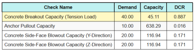
Ecco i rapporti risultanti per tutti controlli di trazione.
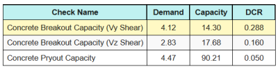
Ecco i rapporti risultanti per tutti controlli a taglio.
Primo, controlliamo utilizzando Eq. (7.55) e confrontare il risultato con quello limite massimo di interazione di 1.0.
\(IO_{\testo{caso1}} = sinistra(\sinistra(\frac{N_{Ed}}{N_{Rd}}\giusto)^{1.5}\giusto) + \sinistra(\sinistra(\frac{V_{Ed}}{V_{Rd}}\giusto)^{1.5}\giusto)\)
\(IO_{\testo{caso1}} = sinistra(\sinistra(\frac{40}{45.106}\giusto)^{1.5}\giusto) + \sinistra(\sinistra(\frac{4.1231}{14.296}\giusto)^{1.5}\giusto) = 0.99\)
Successivamente, controlliamo utilizzando Eq. (7.56) e confrontare il risultato con quello limite massimo di interazione di 1.2.
\(IO_{\testo{caso2}} = frac{N_{Ed}}{N_{Rd}} + \frac{V_{Ed}}{V_{Rd}} = frac{40}{45.106} + \frac{4.1231}{14.296} = 1.1752\)
Da 0.99 < 1.0 e 1.175 < 1.2, il verifica dell'interazione dei guasti concreti è sufficiente.
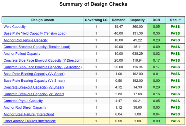
Riepilogo del progetto
La Software di progettazione della piastra di base Skyciv Può generare automaticamente un rapporto di calcolo passo-passo per questo esempio di progettazione. Fornisce inoltre un riepilogo dei controlli eseguiti e dei loro rapporti risultanti, rendere le informazioni facili da capire a colpo d'occhio. Di seguito è riportata una tabella di riepilogo del campione, che è incluso nel rapporto.
Rapporto campione Skyciv
Scopri il livello di dettaglio e chiarezza che puoi aspettarti da un rapporto sulla progettazione della piastra base SkyCiv. Il rapporto include tutti i controlli chiave della progettazione, equazioni, e i risultati presentati in un formato chiaro e di facile lettura. È pienamente conforme agli standard di progettazione. Fare clic di seguito per visualizzare un rapporto di esempio generato utilizzando il calcolatore della piastra di base SkyCiv.
(Il report di esempio verrà aggiunto presto)
Acquista software di base
Acquista da solo la versione completa del modulo di progettazione della piastra di base senza altri moduli SkyCiv. Questo ti dà un set completo di risultati per la progettazione della piastra di base, tra cui report dettagliati e più funzionalità.