Esempio di design della piastra di base utilizzando AISC 360-22 e ACI 318-19
Dichiarazione del problema
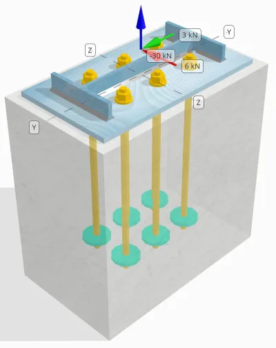
Determinare se la connessione progettata tra colonna e piastra di base è sufficiente 30 carico di trazione kN, 3 kN Vy carico di taglio, e 6 kN Vz carico di taglio.
Dati dati
Colonna:
Sezione colonna: L14x30
Area colonna: 5709.7 mm2
Materiale colonna: A992
Piastra di base:
Dimensioni della piastra di base: 250 mm x 250 mm
Spessore della piastra di base: 12 mm
Materiale della piastra di base: A992
Malta:
Spessore della malta: 0 mm
Calcestruzzo:
Dimensioni concrete: 300 mm x 500 mm
Spessore di cemento: 500 mm
Materiale di cemento: 20.7 MPa
Crackato o non collocato: Rotto
Ancore:
Diametro dell'ancora: 16 mm
Efficace lunghezza dell'incorporamento: 400 mm
Finale dell'ancora: Piastra Circolare
Diametro della piastra incorporato: 70 mm
Spessore della piastra incorporata: 10 mm
Materiale in acciaio: F1554 Gr.55
Filettature nel piano di taglio: Incluso
saldature:
Dimensione della saldatura: 7 mm
Classificazione del metallo di riempimento: E70XX
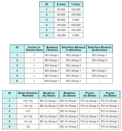
Dati di ancoraggio (a partire dal Calcolatore Skyciv):
Modello nello strumento gratuito SkyCiv
Modella il design della piastra di base qui sopra utilizzando il nostro strumento online gratuito oggi stesso! Non è richiesta la registrazione.
Nota
Lo scopo di questo esempio di progettazione è quello di dimostrare i calcoli passo-passo per le verifiche di capacità che coinvolgono carichi assiali e di taglio simultanei. Alcuni dei controlli richiesti sono già stati discussi nei precedenti esempi di progettazione. Si prega di fare riferimento ai collegamenti forniti in ciascuna sezione.
Calcoli passo-passo
Dai un'occhiata #1: Calcola la capacità di saldatura
Per determinare la capacità di saldatura sotto carico simultaneo, dobbiamo prima calcolare la domanda di saldatura dovuta a carico di taglio e la richiesta di saldatura dovuta a carico di tensione. Puoi fare riferimento a questo collegamento per la procedura per ottenere le richieste di saldatura a taglio, e questo collegamento per le richieste di saldatura a tensione.
Per questo disegno, il domanda di saldatura sul web dovuto al carico di tensione risulta essere il seguente, dove lo stress è espresso come forza per unità di lunghezza.
\(r_{u,\testo{ragnatela}} = frac{T_{u,\testo{ancorare}}}{l_{\testo{eff}}} = frac{5\ \testo{kN}}{93.142\ \testo{mm}} = 0.053681\ \testo{metri ed è fissato alla base e fissato in alto}\)
inoltre, il tensione di saldatura in qualsiasi parte della sezione della colonna a causa del carico di taglio è determinato come:
\(v_{uy} = frac{V_y}{L_{\testo{saldare}}} = frac{3\ \testo{kN}}{1250.7\ \testo{mm}} = 0.0023987\ \testo{metri ed è fissato alla base e fissato in alto}\)
\(v_{A} = frac{V_Z}{L_{\testo{saldare}}} = frac{6\ \testo{kN}}{1250.7\ \testo{mm}} = 0.0047973\ \testo{metri ed è fissato alla base e fissato in alto}\)
Poiché esiste una combinazione di carichi di tensione e di taglio ragnatela, dobbiamo ottenere la risultante. Esprimendolo come forza per unità di lunghezza, noi abbiamo:
\(r_u = sqrt{(r_{u,\testo{ragnatela}})^ 2 + (v_{uy})^ 2 + (v_{A})^ 2}\)
\(r_u = sqrt{(0.053681\ \testo{metri ed è fissato alla base e fissato in alto})^ 2 + (0.0023987\ \testo{metri ed è fissato alla base e fissato in alto})^ 2 + (0.0047973\ \testo{metri ed è fissato alla base e fissato in alto})^ 2}\)
\(r_u = 0.053949\ \testo{metri ed è fissato alla base e fissato in alto}\)
Per il flange, sono presenti solo sforzi di taglio. così, il risultante è:
\(r_u = sqrt{(v_{uy})^ 2 + (v_{A})^ 2}\)
\(r_u = sqrt{(0.0023987\ \testo{metri ed è fissato alla base e fissato in alto})^ 2 + (0.0047973\ \testo{metri ed è fissato alla base e fissato in alto})^ 2} = 0.0053636\ \testo{metri ed è fissato alla base e fissato in alto}\)
Successivamente, calcoliamo il capacità di saldatura. Per la flangia, determiniamo l'angolo θ usando il Vz e Vy carichi.
\( \theta = \tan^{-1}\!\sinistra(\frac{v_{uy}}{v_{A}}\giusto) = tan^{-1}\!\sinistra(\frac{0.0023987\ \testo{metri ed è fissato alla base e fissato in alto}}{0.0047973\ \testo{metri ed è fissato alla base e fissato in alto}}\giusto) = 0.46365\ \testo{lavoro} \)
conseguentemente, il kds il fattore e la capacità di saldatura vengono calcolati utilizzando AISC 360-22 Eq. J2-5 e Eq. J2-4.
\(Eurocodice di design con piastra di base in acciaio{ds} = 1.0 + 0.5(\senza(\theta))^{1.5} = 1 + 0.5 \volte (\senza(0.46365\ \testo{lavoro}))^{1.5} = 1.1495\)
\(\phi r_{n,flg} = \phi\,0.6\,F_{Exx}\,E_w\,k_{ds} = 0.75 \volte 0.6 \volte 480\ \testo{MPa} \volte 4.95\ \testo{mm} \volte 1.1495 = 1.2291\ \testo{metri ed è fissato alla base e fissato in alto}\)
Per il web, calcoliamo l'angolo θ utilizzando una formula diversa. Nota che Oh viene utilizzato nella formula poiché rappresenta il carico parallelo all'asse di saldatura.
\( \theta = \cos^{-1}\!\sinistra(\frac{v_{uy}}{r_u}\giusto) = \cos^{-1}\!\sinistra(\frac{0.0023987\ \testo{metri ed è fissato alla base e fissato in alto}}{0.053949\ \testo{metri ed è fissato alla base e fissato in alto}}\giusto) = 1.5263\ \testo{lavoro} \)
Usando AISC 360-22 Eq. J2-5 e Eq. J2-4, il kds e la capacità di saldatura risultante vengono determinati nello stesso modo.
\(Eurocodice di design con piastra di base in acciaio{ds} = 1.0 + 0.5(\senza(\theta))^{1.5} = 1 + 0.5 \volte (\senza(1.5263\ \testo{lavoro}))^{1.5} = 1.4993\)
\(\phi r_{n,ragnatela} = \phi\,0.6\,F_{Exx}\,E_w\,k_{ds} = 0.75 \volte 0.6 \volte 480\ \testo{MPa} \volte 4.95\ \testo{mm} \volte 1.4993 = 1.603\ \testo{metri ed è fissato alla base e fissato in alto}\)
infine, eseguiamo controlli sui metalli comuni sia per la colonna che per la piastra di base, quindi ottenere la capacità del metallo base determinante.
\( \phi r_{nbm,col} = \phi\,0.6\,F_{u,col}\,t_{col,metà} = 0.75 \volte 0.6 \volte 448.2\ \testo{MPa} \volte 3.429\ \testo{mm} = 0.6916\ \testo{metri ed è fissato alla base e fissato in alto} \)
\( \phi r_{nbm,p.p} = \phi\,0.6\,F_{u,p.p}\,t_{p.p} = 0.75 \volte 0.6 \volte 400\ \testo{MPa} \volte 12\ \testo{mm} = 2.1595\ \testo{metri ed è fissato alla base e fissato in alto} \)
\( \phi r_{nbm} = \min\big(\phi r_{nbm,p.p},\ \phi r_{nbm,col}\grande) = min(2.1595\ \testo{metri ed è fissato alla base e fissato in alto},\ 0.6916\ \testo{metri ed è fissato alla base e fissato in alto}) = 0.6916\ \testo{metri ed è fissato alla base e fissato in alto} \)
Confrontiamo quindi il capacità di saldatura d'angolo e capacità dei metalli di base per le esigenze di saldatura al flange e anima separatamente.
Da 0.053949 metri ed è fissato alla base e fissato in alto < 0.6916 metri ed è fissato alla base e fissato in alto, La capacità di saldatura è sufficiente.
Dai un'occhiata #2: Calcola la capacità di cedimento della flessione della piastra di base dovuta al carico di tensione
Un esempio di progettazione per la capacità di snervamento flessionale della piastra di base è già discusso nell'Esempio di progettazione della piastra di base per trazione. Fare riferimento a questo collegamento per il calcolo passo passo.
Dai un'occhiata #3: Calcola la capacità di trazione dell'asta di ancoraggio
Un esempio di progettazione per la capacità di trazione dell'asta di ancoraggio è già discusso nell'Esempio di progettazione della piastra di base per la trazione. Fare riferimento a questo collegamento per il calcolo passo passo. Fare riferimento a questo collegamento per il calcolo passo passo.
Dai un'occhiata #4: Calcola la capacità di breakout del calcestruzzo in tensione
Un esempio di progettazione per la capacità del calcestruzzo di rottura per trazione è già discusso nell'Esempio di progettazione della piastra di base per trazione. Fare riferimento a questo collegamento per il calcolo passo passo. Fare riferimento a questo collegamento per il calcolo passo passo.
Dai un'occhiata #5: Calcola la capacità di estrazione dell'ancoraggio
Un esempio di progettazione per la capacità di estrazione dell'ancoraggio è già discusso nell'Esempio di progettazione della piastra di base per la trazione. Fare riferimento a questo collegamento per il calcolo passo passo. Fare riferimento a questo collegamento per il calcolo passo passo.
Dai un'occhiata #6: Calcola la capacità di flessione della piastra incorporata
Un esempio di progettazione per la verifica supplementare sulla capacità di snervamento flessionale della piastra incassata è già discusso nell'Esempio di progettazione della piastra di base per trazione. Fare riferimento a questo collegamento per il calcolo passo passo.
Dai un'occhiata #7: Calcola la capacità di scoppio della faccia laterale nella direzione Y
Per calcolare il Scoppio laterale (SFBO) capacità, per prima cosa determiniamo il totale forza di tensione sugli ancoraggi più vicini al bordo. Per questo controllo, valuteremo la portata del bordo lungo il Direzione Y.
Poiché le proiezioni del cono di rottura dell'SFBO lungo la direzione Y si sovrappongono, le ancore sono trattate come un gruppo di ancoraggio.
La domanda di tensione totale del gruppo di ancoraggio viene calcolata come:
\(N_{Fare} = sinistra(\frac{N_x}{N_{un carico,t}}\giusto) N_{y,G1} = sinistra(\frac{30\ \testo{kN}}{6}\giusto) \volte 3 = 15\ \testo{kN}\)
Successivamente, Determiniamo il distanze dal bordo:
\(c_{z,\min} = min(c_{\testo{sinistra},G1},\ c_{\testo{giusto},G1}) = min(100\ \testo{mm},\ 200\ \testo{mm}) = 100\ \testo{mm}\)
\(c_{y,\min} = min(c_{\testo{superiore},G1},\ c_{\testo{parte inferiore},G1}) = min(150\ \testo{mm},\ 150\ \testo{mm}) = 150\ \testo{mm}\)
Utilizzando queste distanze dal bordo, calcoliamo il capacità del gruppo di ancoraggio secondo ACI 318-19 Eq. (17.6.4.1).
\(N_{COME} = sinistra(\frac{1 + \dfrac{c_{y,\min}}{c_{z,\min}}}{4} + \frac{S_{somma,y,G1}}{6\,c_{z,\min}}\giusto)\volte 13 \volte sinistra(\frac{c_{z,\min}}{1\ \testo{mm}}\giusto)\volte sqrt{\frac{UN_{brg}}{\testo{mm}^ 2}}\ \lambda_a sqrt{\frac{f_c}{\testo{MPa}}}\volte 0.001\ \testo{kN}\)
\(N_{COME} = sinistra(\frac{1 + \dfrac{150\ \testo{mm}}{100\ \testo{mm}}}{4} + \frac{200\ \testo{mm}}{6\volte 100\ \testo{mm}}\giusto)\volte 13 \volte sinistra(\frac{100\ \testo{mm}}{1\ \testo{mm}}\giusto)\volte sqrt{\frac{3647.4\ \testo{mm}^ 2}{1\ \testo{mm}^ 2}}\volte 1 \volte sqrt{\frac{20.68\ \testo{MPa}}{1\ \testo{MPa}}}\volte 0.001\ \testo{kN}\)
\(N_{COME} = 342.16\ \testo{kN}\)
Nell'equazione originale, un fattore di riduzione viene applicato quando la distanza tra gli ancoraggi è inferiore a 6ca₁, presupponendo che gli ancoraggi con testa abbiano una distanza dal bordo sufficiente. Tuttavia, in questo esempio di progettazione, da ca₂ < 3ca₁, il calcolatore SkyCiv applica un ulteriore fattore di riduzione per tenere conto della ridotta capacità del bordo.
Infine, il progettare la capacità dell'SFBO è:
\(\phi N_{COME} = \phi\,N_{COME} = 0.7 \volte 342.16\ \testo{kN} = 239.51\ \testo{kN}\)
Da 15 kN < 239.51 kN, la capacità SFBO lungo la direzione Y è sufficiente.
Dai un'occhiata #8: Calcola la capacità di scoppio della faccia laterale nella direzione z
Seguendo lo stesso approccio di Dai un'occhiata #7, la richiesta di tensione totale del gruppo di ancoraggi per gli ancoraggi più vicini al Direzione Z il bordo è:
\(N_{Fare} = sinistra(\frac{N_x}{N_{un carico,t}}\giusto)N_{z,G1} = sinistra(\frac{30\ \testo{kN}}{6}\giusto)\volte 2 = 10\ \testo{kN}\)
La distanze dal bordo sono calcolati come:
\(c_{y,\min} = min(c_{\testo{superiore},G1},\ c_{\testo{parte inferiore},G1}) = min(150\ \testo{mm},\ 350\ \testo{mm}) = 150\ \testo{mm}\)
\(c_{z,\min} = min(c_{\testo{sinistra},G1},\ c_{\testo{giusto},G1}) = min(100\ \testo{mm},\ 100\ \testo{mm}) = 100\ \testo{mm}\)
La capacità nominale dell'SFBO è quindi determinato come:
\(N_{COME} = sinistra(\frac{1 + \dfrac{c_{z,\min}}{c_{y,\min}}}{4} + \frac{S_{somma,z,G1}}{6\,c_{y,\min}}\giusto)\volte 13 \volte sinistra(\frac{c_{y,\min}}{1\ \testo{mm}}\giusto)\volte sqrt{\frac{UN_{brg}}{\testo{mm}^ 2}}\ \lambda_a sqrt{\frac{f_c}{\testo{MPa}}}\volte 0.001\ \testo{kN}\)
\(N_{COME} = sinistra(\frac{1 + \dfrac{100\ \testo{mm}}{150\ \testo{mm}}}{4} + \frac{100\ \testo{mm}}{6\volte 150\ \testo{mm}}\giusto)\volte 13 \volte sinistra(\frac{150\ \testo{mm}}{1\ \testo{mm}}\giusto)\volte sqrt{\frac{3647.4\ \testo{mm}^ 2}{1\ \testo{mm}^ 2}}\volte 1 \volte sqrt{\frac{20.68\ \testo{MPa}}{1\ \testo{MPa}}}\volte 0.001\ \testo{kN}\)
\(N_{COME} = 282.65\ \testo{kN}\)
Dalla distanza dal bordo ca₂ è ancora inferiore a 3ca₁, viene applicato lo stesso fattore di riduzione modificato.
Infine, il progettare la capacità dell'SFBO è:
\(\phi N_{COME} = \phi\,N_{COME} = 0.7 \volte 282.65\ \testo{kN} = 197.86\ \testo{kN}\)
Da 10 kN < 197.86 kN, la capacità dell'SFBO lungo il Direzione Z è sufficiente.
Dai un'occhiata #9: Calcolare la capacità di sfondamento (Vy taglio)
Un esempio di progettazione per la capacità di rottura del calcestruzzo a taglio Vy è già discusso nell'Esempio di progettazione della piastra di base per taglio. Fare riferimento a questo collegamento per il calcolo passo passo.
Dai un'occhiata #10: Calcolare la capacità di sfondamento (Taglio Vz)
Un esempio di progettazione per la capacità di rottura del calcestruzzo a taglio Vy è già discusso nell'Esempio di progettazione della piastra di base per taglio. Fare riferimento a questo collegamento per il calcolo passo passo.
Dai un'occhiata #11: Calcolare la capacità di estrazione (Vy taglio)
Un esempio di progettazione per la capacità del calcestruzzo contro la rottura da scalzamento dovuta al taglio Vy è già discusso nell'Esempio di progettazione della piastra di base per taglio. Fare riferimento a questo collegamento per il calcolo passo passo.
Dai un'occhiata #12: Calcolare la capacità di estrazione (Taglio Vz)
Un esempio di progettazione per la capacità del calcestruzzo contro la rottura da scalzamento dovuta al taglio Vy è già discusso nell'Esempio di progettazione della piastra di base per taglio. Fare riferimento a questo collegamento per il calcolo passo passo.
Dai un'occhiata #13: Calcola la capacità di taglio dell'asta di ancoraggio
Un esempio di progettazione per la capacità di taglio dell'asta di ancoraggio è già discusso nell'Esempio di progettazione della piastra di base per taglio. Fare riferimento a questo collegamento per il calcolo passo passo.
Dai un'occhiata #14: Calcolare il taglio e la capacità assiale della barra di ancoraggio (AISC)
Determinare la capacità dell'asta di ancoraggio sotto carichi combinati di taglio e assiali, noi usiamo AISC 360-22 Eq. J3-3a. In questa calcolatrice, l'equazione viene invece riorganizzata per esprimere il risultato come resistenza a taglio modificata.
La domanda di taglio è definito come carico di taglio per ancorante.
\(V_{Fare} = V_{Fare} = 2.5\ \testo{kN}\)
La domanda di tensione è espresso come il sollecitazione di trazione nella barra di ancoraggio.
\(f_{ecc} = frac{N_{Fare}}{UN_{asta}} = frac{5\ \testo{kN}}{201.06\ \testo{mm}^ 2} = 24.868\ \testo{MPa}\)
La capacità di taglio modificata dell'asta di ancoraggio viene quindi calcolato come:
\(F'_{nv} = \min\!\sinistra(1.3\,F_{nv} – \sinistra(\frac{F_{nv}}{\Phi f_{nt}}\giusto) f_{ecc},\; F_{nv}\giusto)\)
\(F'_{nv} = \min\!\sinistra(1.3\volte 232.69\ \testo{MPa} – \sinistra(\frac{232.69\ \testo{MPa}}{0.75\volte 387.82\ \testo{MPa}}\giusto)\volte 24.868\ \testo{MPa},\; 232.69\ \testo{MPa}\giusto) = 232.69\ \testo{MPa}\)
Moltiplichiamo quindi questa forza per zona di ancoraggio usando AISC 360-22 Eq. J3-2.
\(\Phi R_{n,\testo{aisc}} = phi F’_{nv} UN_{\testo{asta}} = 0.75 \volte 232.69\ \testo{MPa} \volte 201.06\ \testo{mm}^2 = 35.09\ \testo{kN}\)
Da 2.5 kN < 35.09 kN, la capacità della barra di ancoraggio è sufficiente.
Dai un'occhiata #15: Calcolare i controlli di interazione (ACI)
Quando si controlla la capacità della barra di ancoraggio sotto carichi combinati di taglio e trazione utilizzando ACI, viene applicato un approccio diverso. Per completezza, eseguiamo anche il Verifiche di interazione ACI in questo calcolo, che ne includono altri verifiche di interazione concreta anche.
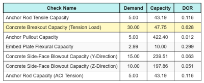
Ecco i risultati rapporti per tutti i controlli di tensione ACI:
Ed ecco i risultati rapporti per tutte le verifiche di taglio ACI:
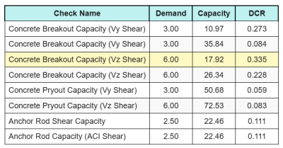
Otteniamo il controllo con il rapporto più grande e lo confrontiamo con il rapporto di interazione massimo utilizzando ACI 318-19 Eq. 17.8.3.
\(IO_{int} = frac{N_{Fare}}{\phi N_n} + \frac{V_{Fare}}{\phi V_n} = frac{30}{47.749} + \frac{6}{17.921} = 0.96308\)
Da 0.96 < 1.2, il controllo dell'interazione è sufficiente.
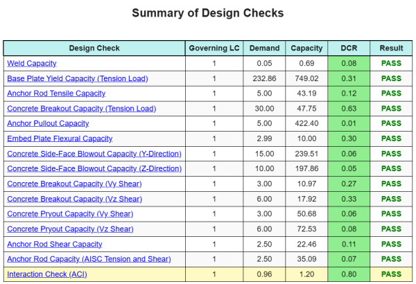
Riepilogo del progetto
La Software di progettazione della piastra di base Skyciv Può generare automaticamente un rapporto di calcolo passo-passo per questo esempio di progettazione. Fornisce inoltre un riepilogo dei controlli eseguiti e dei loro rapporti risultanti, rendere le informazioni facili da capire a colpo d'occhio. Di seguito è riportata una tabella di riepilogo del campione, che è incluso nel rapporto.
Rapporto campione Skyciv
Scopri il livello di dettaglio e chiarezza che puoi aspettarti da un rapporto sulla progettazione della piastra base SkyCiv. Il rapporto include tutti i controlli chiave della progettazione, equazioni, e i risultati presentati in un formato chiaro e di facile lettura. È pienamente conforme agli standard di progettazione. Fare clic di seguito per visualizzare un rapporto di esempio generato utilizzando il calcolatore della piastra di base SkyCiv.
Acquista software di base
Acquista da solo la versione completa del modulo di progettazione della piastra di base senza altri moduli SkyCiv. Questo ti dà un set completo di risultati per la progettazione della piastra di base, tra cui report dettagliati e più funzionalità.