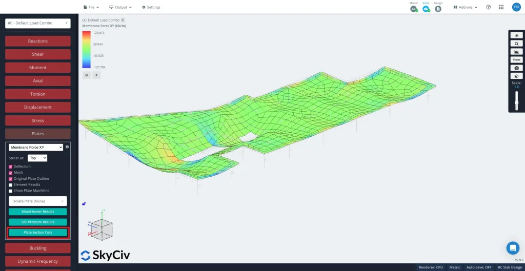
ο Περικοπές τμήματος πλάκας εργαλείο σας επιτρέπει να εξάγετε δυνάμεις, στιγμές, και άλλα αποτελέσματα πλάκας κατά μήκος οποιασδήποτε καθορισμένης γραμμής κοπής κατά μήκος των πλακών, πλάκες, ή τοίχους. Αυτό είναι χρήσιμο για το σχεδιασμό λωρίδων πλάκας, έλεγχος συμπεριφοράς τοπικής πινακίδας, και επαλήθευση κατανομής φορτίου.
Πώς να χρησιμοποιήσετε το εργαλείο κοπής τμημάτων πλακών
Μετά την επίλυση, επιλέγω Πλάκες και μετά Περικοπές τμήματος πλάκας στον αριστερό πίνακα.
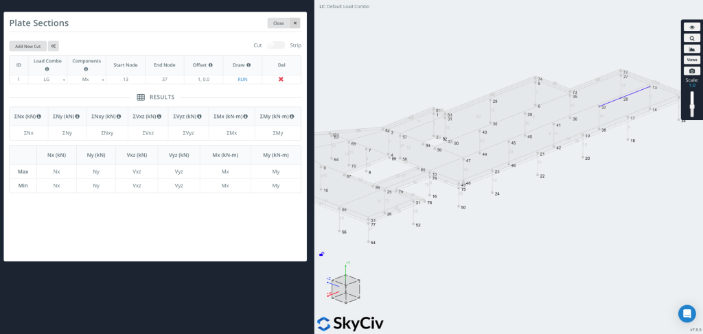
Κάντε κλικ "Προσθήκη νέας περικοπής" για να δημιουργήσετε μια νέα καταχώρηση.
Κάθε περικοπή περιλαμβάνει:
-
Φόρτωση Combo – Επιλέξτε από ποιον συνδυασμό φορτίου θα εξαγάγετε τα αποτελέσματα.
-
Συστατικά – Επιλέξτε τον τύπο αποτελέσματος (π.χ., Μx, Καμπύλες Mz-My και καμπύλες F-M, Nx, Vxz, Wood-Armer, Διπλή διάτμηση).
-
Έναρξη Κόμβου / Τελικός κόμβος – Καθορίστε το τμήμα όπου θα τοποθετηθεί η τομή.
-
Αντισταθμίζεται – Προαιρετικά μετακινήστε τη γραμμή κοπής κατά μια δεδομένη απόσταση (π.χ.,
1,0,0).-
Αυτό είναι χρήσιμο όταν θέλετε ένα γράφημα σε μια καθορισμένη μετατόπιση από μια ακμή χωρίς μη αυτόματο υπολογισμό συντεταγμένων.
-
Τώρα μπορείτε να σχεδιάσετε & Εκτελέστε το Cut
Τύπος ΤΡΕΞΙΜΟ για να δημιουργήσετε το κόψιμο. Η γραμμή κοπής θα εμφανιστεί στο μοντέλο σας (όπως φαίνεται στη δεξιά πλευρά της εικόνας), και το πίνακα αποτελεσμάτων θα συμπληρωθεί με μέγιστες και ελάχιστες τιμές για κάθε επιλεγμένο στοιχείο.
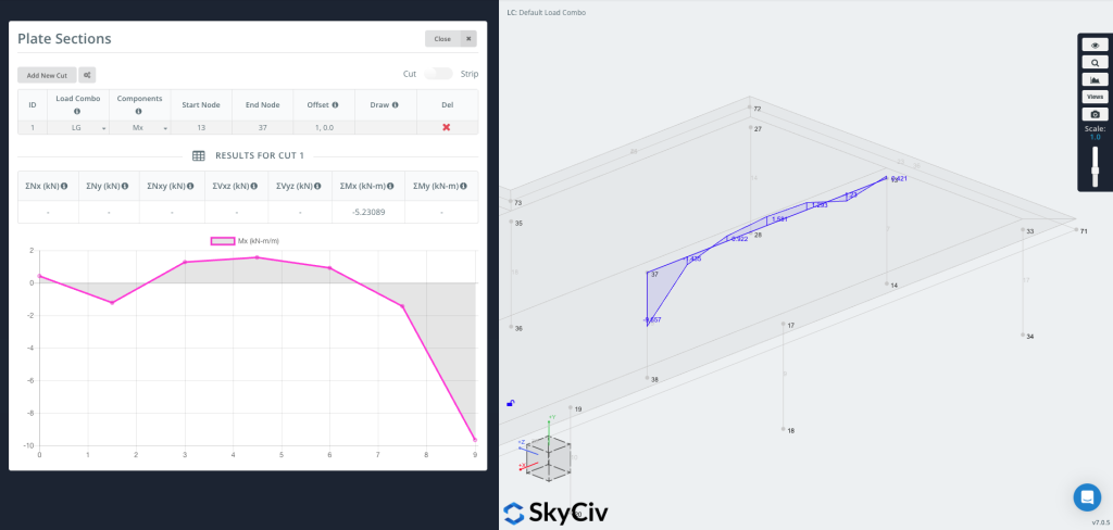
Τώρα μπορείτε να σχεδιάσετε το γράφημα απευθείας στη γεωμετρία, εμφάνιση των τιμών των αποτελεσμάτων οπτικά κατά μήκος της γραμμής κοπής.
Οι χρήστες μπορούν επίσης να δημιουργήσουν ένα τμήμα λωρίδας ενεργοποιώντας τη λειτουργία λωρίδας στην επάνω δεξιά γωνία.
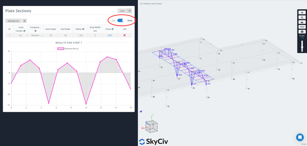
ΕΝΑ Λωρίδα εξάγει αποτελέσματα σε πλάτος, όχι απλώς μια γραμμή. Υπολογίζει τον μέσο όρο των αποτελεσμάτων της πλάκας σε ένα ενεργό πλάτος με επίκεντρο την καθορισμένη γραμμή κοπής—αυτό χρησιμοποιείται συνήθως σχέδιο λωρίδας πλάκας, όπου οι κώδικες σχεδίασης απαιτούν τον υπολογισμό του μέσου όρου των ροπών σε μια λωρίδα πλάκας.
Ένα Strip είναι χρήσιμο όταν το χρειάζεστε:
-
Σχεδιαστικές τιμές για μονόδρομες ή αμφίδρομες ταινίες πλακών
-
Μέσος όρος βάσει κώδικα (συμπεριλαμβανομένου του προαιρετικού κανόνα των δύο τρίτων CSA)
-
Πιο αντιπροσωπευτικές τιμές σε μια φυσική ταινία αντί για μια μεμονωμένη γραμμή