Πώς να αντισταθμίσετε, Μεταφράστε ή προσθέστε σημεία εισαγωγής σε ένα μέλος στο SkyCiv Structural 3D
Οι αντισταθμίσεις μελών είναι μικρές μετατοπίσεις στη θέση ενός μέλους σε μια τοποθεσία πιο κοντά στην εκπροσώπηση του πραγματικού κόσμου του.
Από προεπιλογή, Το λογισμικό S3D του SkyCiv συμμετέχει στον κόμβο των μελών στον κόμβο. Η μονοδιάστατη γραμμή που αντιπροσωπεύει κάθε μέλος μεταξύ των τελικών κόμβων τους βρίσκεται στο κέντρο της διατομής.
Αισθητικώς, Αυτή η προεπιλεγμένη συμπεριφορά δημιουργεί μια επικάλυψη ορισμένων μελών που δεν μπορούσαν να συμβούν ρεαλιστικά. Επιπλέον, Μικρές στιγμές ή δυνάμεις μπορούν να υπάρχουν σε δομές πραγματικού κόσμου λόγω των παρακείμενων μελών που δεν συμμετέχουν στην πραγματικότητα στο Centroid στο Centroid. Ως εκ τούτου, χρησιμοποιούνται οι αντισταθμίσεις μελών για την επίλυση αυτών των προβλημάτων.
Άξονας αντιστάθμισης
Οι αντισταθμίσεις μελών ορίζονται από μια είσοδο τριών συμβολοσειρών που αντιπροσωπεύει την απόσταση μετατόπισης σε κάθε κατεύθυνση του άξονα: [άξονας x, άξονας y, άξονας z]. Αυτό καθορίζει ότι τα μέλη αντισταθμίζονται από μια συγκεκριμένη τιμή χιλιοστών (ίντσες εάν χρησιμοποιείτε το Imperial) προς την κατεύθυνση του καθορισμένου τοπικού άξονα. ο τοπικός άξονας Πρέπει να χρησιμοποιείται για την εντολή αντιστάθμισης λόγω της σύγχυσης που μπορεί να προκύψει μέσα σε ένα τρισδιάστατο χώρο όταν δύο μέλη βρίσκονται σε δύο εντελώς διαφορετικά επίπεδα. Για παράδειγμα, εάν τα μέλη είναι σε διαγώνιο στον παγκόσμιο άξονα που αντισταθμίζει μέσω παγκόσμιων μετρήσεων θα ήταν δύσκολη και χρονοβόρα θα ήταν δύσκολη και χρονοβόρα.
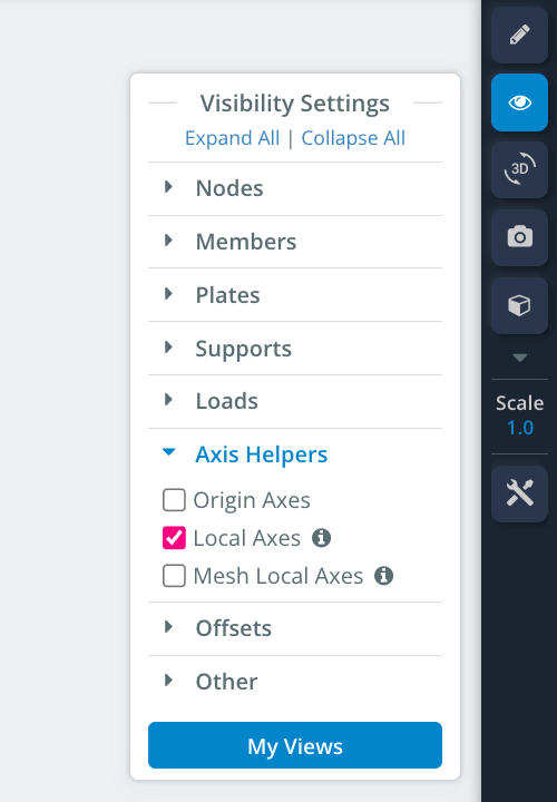
Το μέλος του τοπικού άξονα μπορεί να εμφανιστεί στην προβολή πλαισιωμένου καλωδίου, μεταφέροντας τις ρυθμίσεις ορατότητας και ενεργοποιώντας τις όπως φαίνεται παρακάτω:
Αντισταθμίζοντας ένα μέλος
Ένα μέλος μπορεί να αντισταθμιστεί κάνοντας κλικ στο μέλος και εισάγοντας την τιμή της μετατόπισης στην αντίστοιχη ενότητα άξονα των παρακάτω [άξονας x, άξονας y, άξονας z], Αρχικά ρυθμίστηκε ως [0,0,0] Λόγω της έλλειψης αρχικής μετατόπισης. Η χρήση ενός αρνητικού αριθμού θα αντισταθμίσει το μέλος στην αρνητική κατεύθυνση ως τοπικός άξονας.
Για να αποκτήσετε πρόσβαση στις επιλογές μετατόπισης, Βεβαιωθείτε ότι έχετε αλλάξει το “Προχωρημένος” μεταβείτε στη θέση ON.
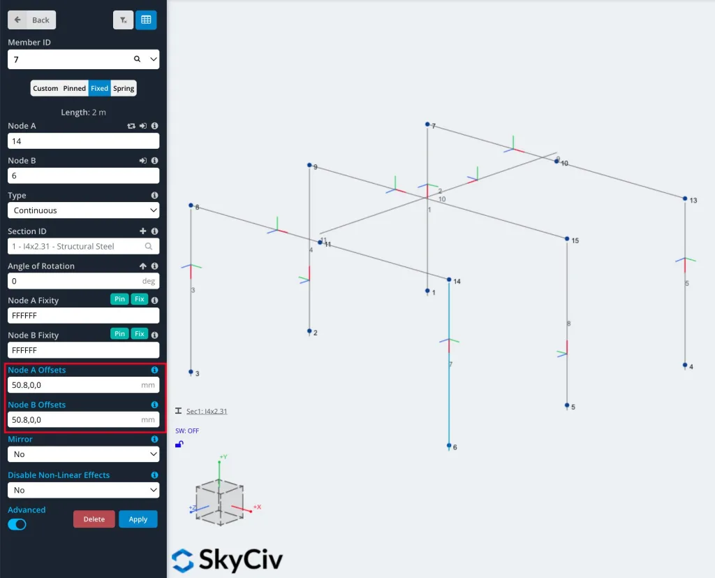
Παρακάτω παρουσιάζεται ένα παράδειγμα πλαισίου χωρίς αντισταθμίσεις μελών. Σημειώστε ότι οι μετατοπίσεις σε ένα μέλος μπορούν να γίνουν σε ένα μόνο άκρο ή και στα δύο άκρα.
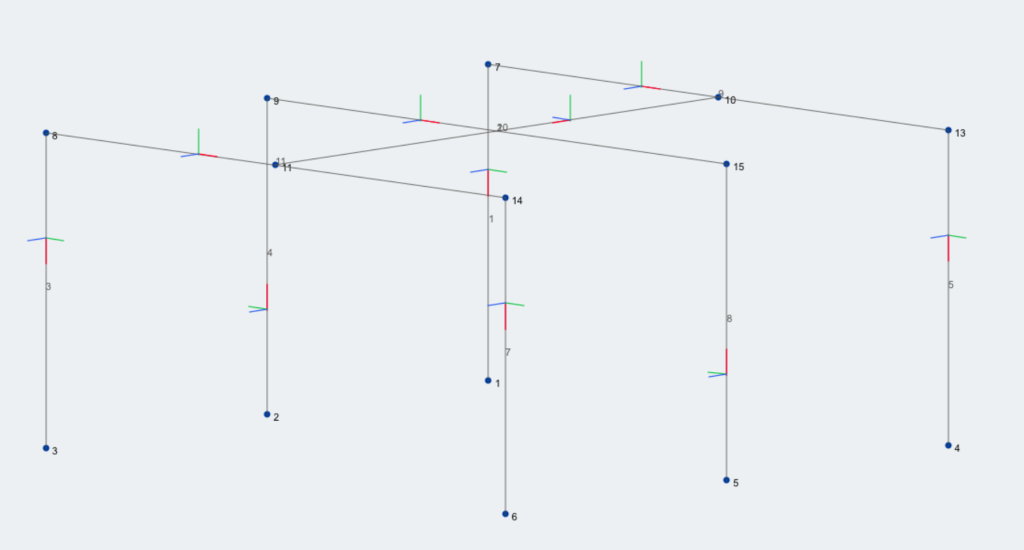
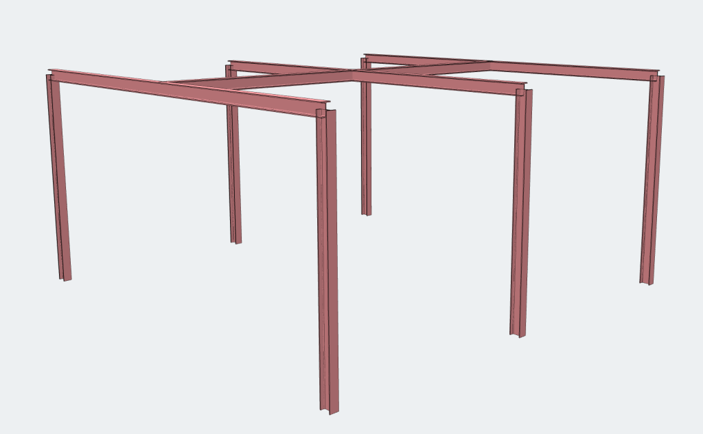
Μπορείτε να δείτε παραπάνω ότι οι γωνίες των μελών του πλαισίου είναι πάνω από το κτύπημα και ότι το purlin κάθεται μέσα στο δοκός πλαισίου και όχι στην κορυφή.
Παρακάτω εμφανίζεται το ίδιο πλαίσιο αλλά με τη χρήση των αντισταθμίσεων μελών:
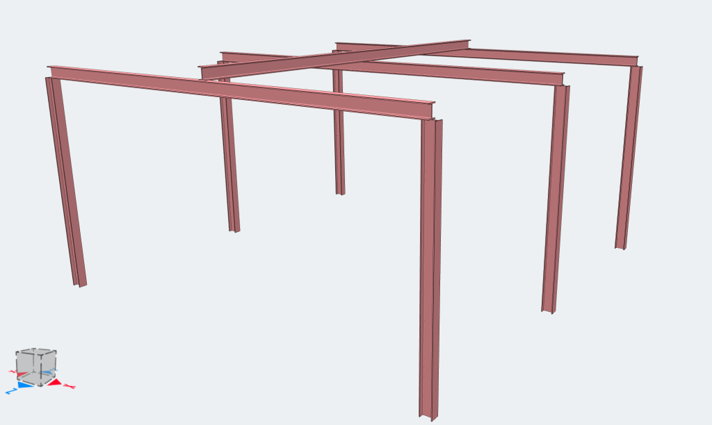
Μπορείτε να δείτε παραπάνω ότι τα δοκάρια τώρα κάθονται στην κορυφή των στηλών αντί για μέσα τους και το παρόμοιο με τα purlins στα δοκάρια.
Παρακάτω εμφανίζεται το ίδιο πλαίσιο αλλά στην προβολή ενσύρματου πλαισίου:
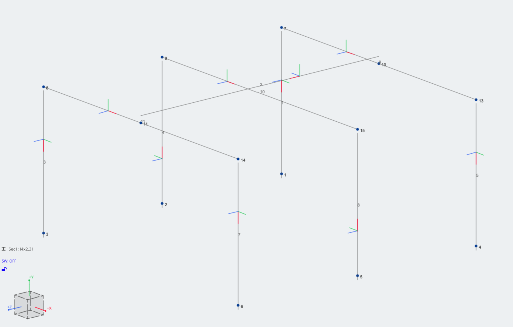
Πώς λειτουργούν οι αντισταθμίσεις?
Οι αντισταθμίσεις θα δημιουργήσουν “χώρος” μεταξύ ενός μέλους και του κόμβου του, αλλά εξακολουθεί να συνδέεται με τον κόμβο. Συνδέεται με αόρατο Άκαμπτος σύνδεσμος. Ένας άκαμπτος σύνδεσμος είναι ένας φανταστικός σκληρός σύνδεσμος που ενώνει τον κόμβο με την τοποθεσία μετατόπισης μέλους, έτσι ώστε να μεταφράζουν τέλεια φορτία, εκτροπή και περιστροφές μεταξύ τους.
Δεδομένου ότι τα μέλη δεν είναι πλέον συνδεδεμένα στα μέσα τους, Αυτός ο άκαμπτος σύνδεσμος θα δημιουργήσει ένα μικρό βραχίονα στιγμής και επομένως θα επηρεάσει τις εσωτερικές δυνάμεις του μέλους του μέλους. Μπορεί να δημιουργήσει πρόσθετες δυνάμεις στρεπτικής ή κάμψης στο μέλος. Πολλές φορές αυτές οι τιμές είναι αρκετά ελάχιστες και συχνά μπορούν να θεωρηθούν αμελητέες.
Διαβάστε περισσότερα για τους άκαμπτους συνδέσμους και τη συμπεριφορά τους στο Μέλος τεκμηρίωση.
Σημείωση όταν χρησιμοποιείτε αντισταθμίσεις
Είναι σημαντικό να είστε προσεκτικοί όταν χρησιμοποιείτε αντισταθμίσεις και άκαμπτους συνδέσμους για να διασφαλίσετε ότι τα μέλη εξακολουθούν να συνδέονται σωστά. Για παράδειγμα, Εάν επισυνάψετε έναν άκαμπτο σύνδεσμο σε υποστήριξη FFFRRR (Η σταθερή μετάφραση είναι όλες οι οδηγίες – ελεύθερος να περιστρέφεται προς όλες τις κατευθύνσεις), Μπορείτε να αναμένετε ότι το μέλος θα εξακολουθεί να υποστηρίζεται στο x,ΚΑΙ,Z μετάφραση. Ωστόσο, Ο άκαμπτος σύνδεσμος είναι τεχνικά ελεύθερος να περιστρέφεται και οι δυνάμεις μπορεί να μην μεταφέρουν όπως προβλέπεται:
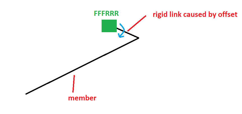
(Σημείωση: Σε αυτή την περίπτωση, μια σωστή ρύθμιση μπορεί να είναι μια πλήρως σταθερή υποστήριξη και στη συνέχεια FFFRRR στο τέλος του μέλους για να περιορίσει το άκαμπτο μέλος από την περιστροφή)
Σημεία εισαγωγής
Τα σημεία εισαγωγής είναι ένας κοινός τρόπος για τον έλεγχο της τοποθέτησης της σύνδεσης με ένα μέλος. Από προεπιλογή, Το μέλος θα συνδεθεί με άλλα στοιχεία μέσω του κέντρου του. Με σημεία εισαγωγής, Μπορείτε να το μετακινήσετε σε άλλα βασικά σημεία του τμήματος. Τα σημεία εισαγωγής βασίζονται στην ίδια λειτουργικότητα με τις αντισταθμίσεις για την εξισορρόπηση της ακρίβειας του λογισμικού με μια καθαρή και εύκολη εμπειρία χρήστη.
Τα σημεία εισαγωγής είναι εύκολο να ελεγχθούν χρησιμοποιώντας αντισταθμίσεις μελών:
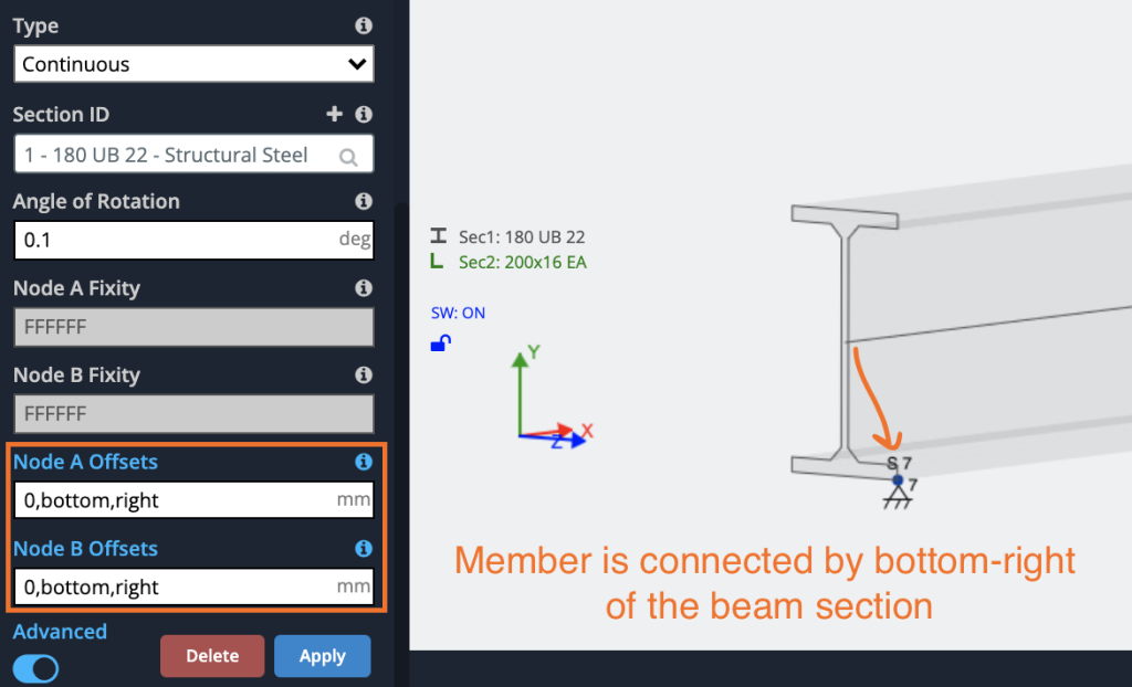
Τα σημεία εισαγωγής μπορούν να οριστούν από τα παρακάτω:
- Πρώτη καταχώρηση – Αριθμός μόνο
- Δεύτερη καταχώρηση – μπλουζα, κάτω μέρος, διάτμηση ή κέντρο
- Τρίτη καταχώρηση – σωστά, αριστερά, διάτμηση ή κέντρο
- Τέταρτη καταχώρηση – (Προαιρετικός) Προσθέτοντας ένα 4ο επιχείρημα ως “βείναι”, Ο διαλυτής θα αγνοήσει τις αντισταθμίσεις στην ανάλυση, και χρησιμοποιήστε τα μόνο στα γραφικά.
Συνδυάζοντας αυτές τις επιλογές, Οι χρήστες μπορούν να μεταφέρουν τα σημεία εισαγωγής τους στο σημείο που χρειάζονται στο μέλος:
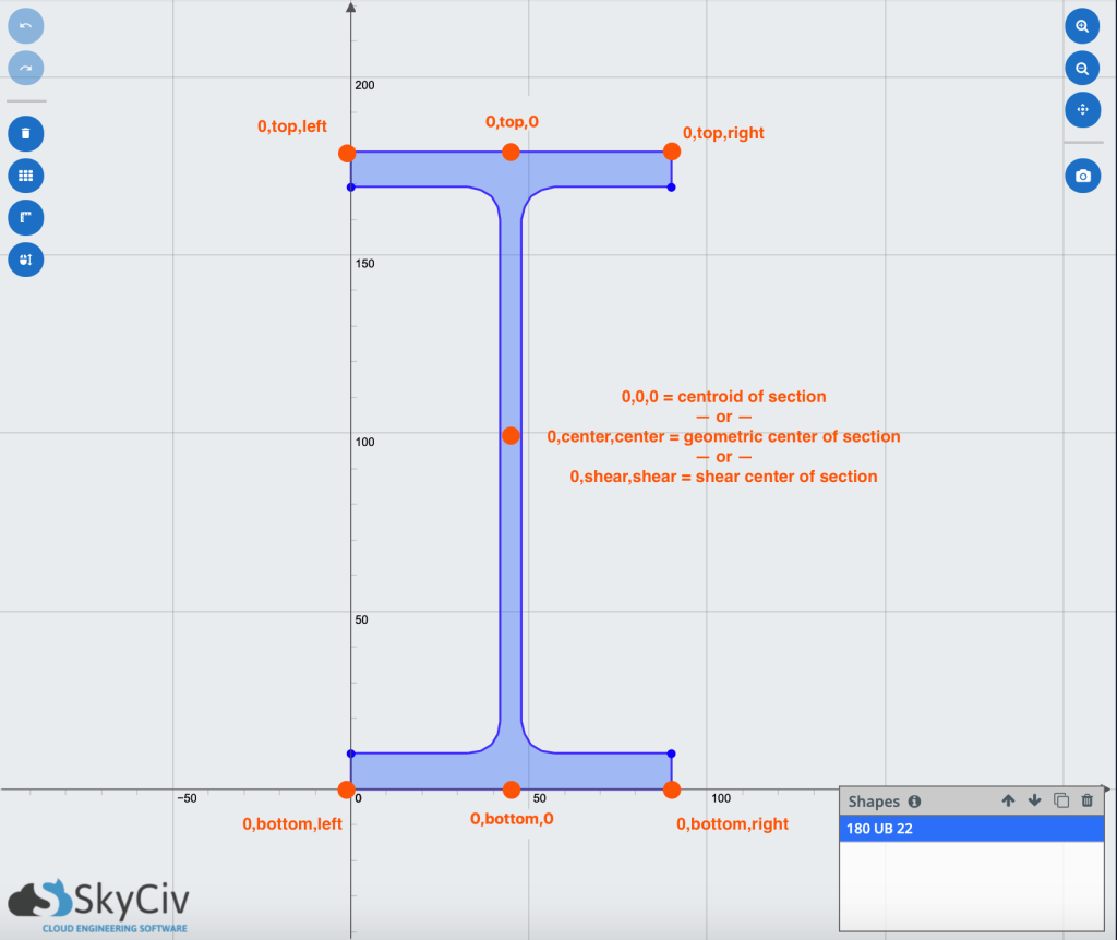
Μερικά κοινά σημεία εισαγωγής μιας δέσμης – Σημείωση: Οι χρήστες μπορούν να αναμειγνύονται και να ταιριάζουν με τις διαφορετικές εισόδους
Μερικά κοινά παραδείγματα:
| 0,μπλουζα,0 | Σημείο εισαγωγής στην κορυφή της δέσμης |
| 0,μπλουζα,σωστά | Σημείο εισαγωγής στο πάνω δεξιά της δέσμης |
| 0,κάτω μέρος,αριστερά,οπτικός | Σημείο εισαγωγής στο κάτω αριστερό μέρος της δέσμης, αγνοήστε την αντιστάθμιση στην ανάλυση (Χρησιμοποιήστε μόνο για απεικόνιση) |
| 0,κουρεύω,κουρεύω | Σημείο εισαγωγής στο κέντρο διάτμησης τμήματος |
| 0,0,σωστά | Σημείο εισαγωγής στο κεντροειδές-δεξιά της δέσμης |
| 0,τ,ρ | Σημείο εισαγωγής στην κορυφαία δεξιά της δέσμης |
Σημείωση: για όλες τις παραπάνω εισόδους, Οι χρήστες μπορούν να εισέλθουν μόνο στο πρώτο γράμμα ως συντόμευση. Π.χ. “0,τ,μεγάλο” θα ήταν το ίδιο με την είσοδο “0, μπλουζα, αριστερά”
Τα αποτελέσματα των σημείων εισαγωγής
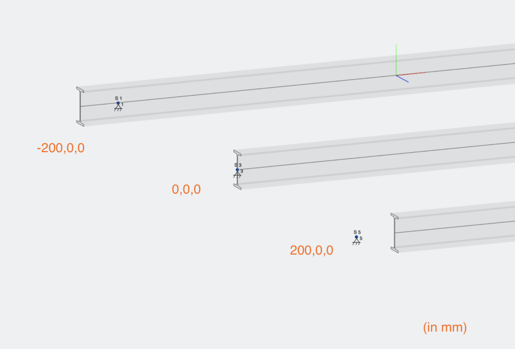
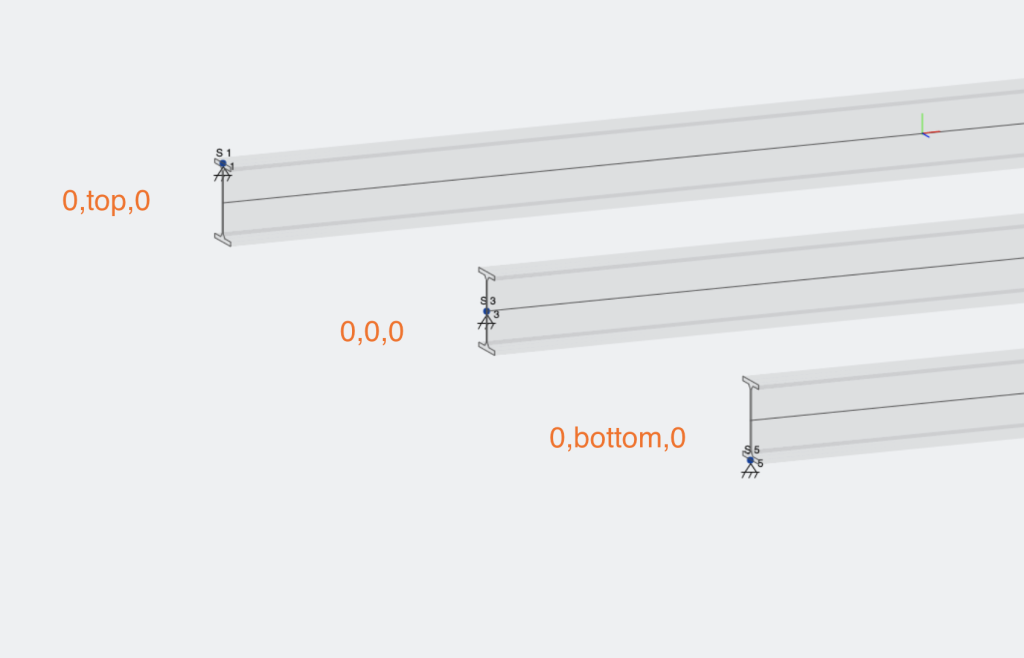
Παρακάτω είναι μερικά παραδείγματα των επιπτώσεων διαφορετικών σημείων εισαγωγής. Συμπεριλαμβάνοντας ένα σημείο εισαγωγής, Ένα άκαμπτο μέλος θα εισαχθεί στα άκρα του μέλους για να αντισταθμίσει τη θέση του κεντροειδούς. Έτσι στο παρακάτω παράδειγμα, Έχουμε τρία πιθανά σημεία εισαγωγής:
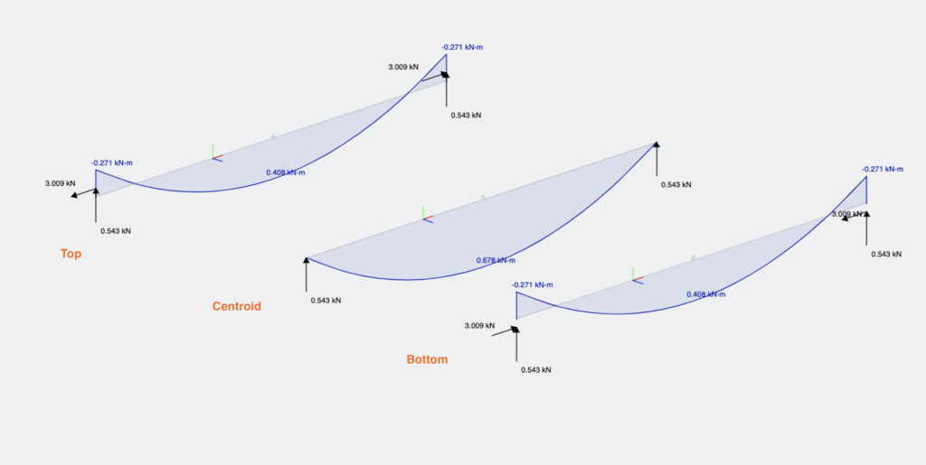
Τα διαφορετικά σημεία εισαγωγής θα έχουν διαφορετικές επιδράσεις τόσο στην εκτροπή, αντιδράσεις και διαγράμματα ροπής κάμψης μελών:
Σημεία εισαγωγής (αντισταθμίσεις) Μπορεί επίσης να υπάρχει κατά μήκος ενός μέλους εισάγοντας έναν αριθμό ως την πρώτη είσοδο, εδώ είναι 3 παραδείγματα τέτοιων:
