Παράδειγμα σχεδιασμού πλάκας βάσης χρησιμοποιώντας AISC 360-22 και ACI 318-19
Προβληματική δήλωση
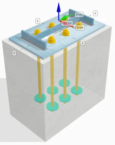
Προσδιορίστε εάν η σχεδιασμένη σύνδεση στήλης-πλάκας βάσης είναι επαρκής για 30 kN φορτίο εφελκυσμού, 3 kN Διατμητικό φορτίο, και 6 kN Vz διατμητικό φορτίο.
Δεδομένα
Στήλη:
Ενότητα στήλης: Μ14Χ30
Επιφάνεια στήλης: 5709.7 χιλ2
Υλικό στήλης: A992
Πλάκα βάσης:
Διαστάσεις πλάκας βάσης: 250 mm x 250 χιλ
Πάχος πλάκας βάσης: 12 χιλ
Υλικό πλάκας βάσης: A992
Πηκτώ:
Πάχος ενέματος: 0 χιλ
Σκυρόδεμα:
Διαστάσεις σκυροδέματος: 300 mm x 500 χιλ
Πάχος σκυροδέματος: 500 χιλ
Σκυρόδεμα: 20.7 MPa
Ραγισμένα ή αδιευκρίνιστα: Ραγισμένος
Άγκυρες:
Διάμετρος άγκυρας: 16 χιλ
Αποτελεσματικό μήκος ενσωμάτωσης: 400 χιλ
Anchor Ending: Κυκλική πλάκα
Διάμετρος ενσωματωμένης πλάκας: 70 χιλ
Ενσωματωμένο πάχος πλάκας: 10 χιλ
Υλικό χάλυβα: F1554 Γρ.55
Νήματα σε επίπεδο διάτμησης: Συμπεριλαμβανομένος
Συγκολλήσεις:
Μέγεθος συγκόλλησης: 7 χιλ
Η ταξινόμηση μετάλλων πλήρωσης: Ε70ΧΧ
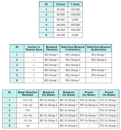
Δεδομένα αγκυροβόλησης (από Υπολογιστής Skyciv):
Μοντέλο στο δωρεάν εργαλείο SkyCiv
Μοντελοποιήστε το παραπάνω σχέδιο πλάκας βάσης χρησιμοποιώντας το δωρεάν διαδικτυακό μας εργαλείο σήμερα! Δεν απαιτείται εγγραφή.
Σημείωση
Ο σκοπός αυτού του παραδείγματος σχεδιασμού είναι να επιδείξει τους βαθμιαίους υπολογισμούς για ελέγχους χωρητικότητας που περιλαμβάνουν ταυτόχρονα διατμητικά και αξονικά φορτία. Ορισμένοι από τους απαιτούμενους ελέγχους έχουν ήδη συζητηθεί στα προηγούμενα παραδείγματα σχεδιασμού. Ανατρέξτε στους συνδέσμους που παρέχονται σε κάθε ενότητα.
Υπολογισμοί βήμα προς βήμα
Ελεγχος #1: Υπολογίστε τη χωρητικότητα συγκόλλησης
Για τον προσδιορισμό της ικανότητας συγκόλλησης υπό ταυτόχρονη φόρτιση, πρέπει πρώτα να υπολογίσουμε τη ζήτηση συγκόλλησης λόγω του διατμητικό φορτίο και η ζήτηση συγκόλλησης λόγω του φορτίο τάσης. Μπορείτε να αναφερθείτε σε αυτό Σύνδεσμος για τη διαδικασία λήψης των απαιτήσεων συγκόλλησης για διάτμηση, και αυτό Σύνδεσμος για τις απαιτήσεις συγκόλλησης τάσης.
Για αυτό το σχέδιο, ο ζήτηση συγκόλλησης στο διαδίκτυο λόγω του φορτίου εφελκυσμού βρέθηκε να είναι ως εξής, όπου το άγχος εκφράζεται ως δύναμη ανά μονάδα μήκους.
\(r_{εσύ,\κείμενο{ιστός}} = frac{T_{εσύ,\κείμενο{άγκυρα}}}{μεγάλο_{\κείμενο{εφ}}} = frac{5\ \κείμενο{ΚΝ}}{93.142\ \κείμενο{χιλ}} = 0.053681\ \κείμενο{kN / mm}\)
Επί πλέον, ο τάση συγκόλλησης σε οποιοδήποτε μέρος του τμήματος της στήλης λόγω του διατμητικού φορτίου προσδιορίζεται ως:
\(v_{uy} = frac{V_y}{ΜΕΓΑΛΟ_{\κείμενο{συγκόλληση}}} = frac{3\ \κείμενο{ΚΝ}}{1250.7\ \κείμενο{χιλ}} = 0.0023987\ \κείμενο{kN / mm}\)
\(v_{να} = frac{V_z}{ΜΕΓΑΛΟ_{\κείμενο{συγκόλληση}}} = frac{6\ \κείμενο{ΚΝ}}{1250.7\ \κείμενο{χιλ}} = 0.0047973\ \κείμενο{kN / mm}\)
Δεδομένου ότι υπάρχει ένας συνδυασμός φορτίων εφελκυσμού και διάτμησης στο ιστός, πρέπει να λάβουμε το αποτέλεσμα. Εκφράζοντας αυτό ως δύναμη ανά μονάδα μήκους, έχουμε:
\(r_u = sqrt{(r_{εσύ,\κείμενο{ιστός}})^ 2 + (v_{uy})^ 2 + (v_{να})^ 2}\)
\(r_u = sqrt{(0.053681\ \κείμενο{kN / mm})^ 2 + (0.0023987\ \κείμενο{kN / mm})^ 2 + (0.0047973\ \κείμενο{kN / mm})^ 2}\)
\(r_u = 0.053949\ \κείμενο{kN / mm}\)
Για το πέλματα, υπάρχουν μόνο διατμητικές τάσεις. Ετσι, το αποτέλεσμα είναι:
\(r_u = sqrt{(v_{uy})^ 2 + (v_{να})^ 2}\)
\(r_u = sqrt{(0.0023987\ \κείμενο{kN / mm})^ 2 + (0.0047973\ \κείμενο{kN / mm})^ 2} = 0.0053636\ \κείμενο{kN / mm}\)
Επόμενο, υπολογίζουμε το χωρητικότητες συγκόλλησης. Για τη φλάντζα, καθορίζουμε τη γωνία θ SkyCiv Renderer API Vz και Εσείς φορτία.
\( \theta = \tan^{-1}\!\αριστερά(\frac{v_{uy}}{v_{να}}\σωστά) = \tan^{-1}\!\αριστερά(\frac{0.0023987\ \κείμενο{kN / mm}}{0.0047973\ \κείμενο{kN / mm}}\σωστά) = 0.46365\ \κείμενο{rad} \)
συνεπώς, ο kds ο συντελεστής και η χωρητικότητα συγκόλλησης υπολογίζονται χρησιμοποιώντας AISC 360-22 Εξ. J2-5 και Εξ. J2-4.
\(κ_{δδ} = 1.0 + 0.5(\χωρίς(\θήτα))^{1.5} = 1 + 0.5 \φορές (\χωρίς(0.46365\ \κείμενο{rad}))^{1.5} = 1.1495\)
\(\phi r_{ν,flg} = phi,0,6,F_{Exx}\,E_w\,k_{δδ} = 0.75 \φορές 0.6 \φορές 480\ \κείμενο{MPa} \φορές 4.95\ \κείμενο{χιλ} \φορές 1.1495 = 1.2291\ \κείμενο{kN / mm}\)
Για τον Ιστό, υπολογίζουμε τη γωνία θ χρησιμοποιώντας διαφορετικό τύπο. Σημειώστε ότι Εκπληκτική επιτυχία χρησιμοποιείται στον τύπο αφού αντιπροσωπεύει το φορτίο παράλληλο προς τον άξονα συγκόλλησης.
\( \theta = \cos^{-1}\!\αριστερά(\frac{v_{uy}}{r_u}\σωστά) = \cos^{-1}\!\αριστερά(\frac{0.0023987\ \κείμενο{kN / mm}}{0.053949\ \κείμενο{kN / mm}}\σωστά) = 1.5263\ \κείμενο{rad} \)
Χρησιμοποιώντας AISC 360-22 Εξ. J2-5 και Εξ. J2-4, ο kds ο συντελεστής και η προκύπτουσα ικανότητα συγκόλλησης προσδιορίζονται με τον ίδιο τρόπο.
\(κ_{δδ} = 1.0 + 0.5(\χωρίς(\θήτα))^{1.5} = 1 + 0.5 \φορές (\χωρίς(1.5263\ \κείμενο{rad}))^{1.5} = 1.4993\)
\(\phi r_{ν,ιστός} = phi,0,6,F_{Exx}\,E_w\,k_{δδ} = 0.75 \φορές 0.6 \φορές 480\ \κείμενο{MPa} \φορές 4.95\ \κείμενο{χιλ} \φορές 1.4993 = 1.603\ \κείμενο{kN / mm}\)
Εν τέλει, εκτελούμε έλεγχοι βασικών μετάλλων τόσο για τη στήλη όσο και για την πλάκα βάσης, στη συνέχεια, λάβετε την ισχύουσα χωρητικότητα βασικού μετάλλου.
\( \phi r_{nbm,διάσελο} = phi,0,6,F_{εσύ,διάσελο}\,αυτό είναι ένα πολύ σημαντικό στάδιο στο σχεδιασμό ενός τοίχου αντιστήριξης, καθώς η μη αντιστοίχιση των σωστών αναλογικών διαστάσεων από την αρχή σε κάθε στοιχείο μπορεί να οδηγήσει στην ανάγκη πολλών επαναλήψεων για να συμμορφωθεί ο τοίχος αντιστήριξης με τις απαιτήσεις ευστάθειας ή υπερμεγέθη σύστημα που πληροί όλες τις απαιτήσεις, αλλά χρησιμοποιεί πολύ περισσότερο υλικό από το θεωρητικό ελάχιστο{διάσελο,ήμισυ} = 0.75 \φορές 0.6 \φορές 448.2\ \κείμενο{MPa} \φορές 3.429\ \κείμενο{χιλ} = 0.6916\ \κείμενο{kN / mm} \)
\( \phi r_{nbm,bp} = phi,0,6,F_{εσύ,bp}\,αυτό είναι ένα πολύ σημαντικό στάδιο στο σχεδιασμό ενός τοίχου αντιστήριξης, καθώς η μη αντιστοίχιση των σωστών αναλογικών διαστάσεων από την αρχή σε κάθε στοιχείο μπορεί να οδηγήσει στην ανάγκη πολλών επαναλήψεων για να συμμορφωθεί ο τοίχος αντιστήριξης με τις απαιτήσεις ευστάθειας ή υπερμεγέθη σύστημα που πληροί όλες τις απαιτήσεις, αλλά χρησιμοποιεί πολύ περισσότερο υλικό από το θεωρητικό ελάχιστο{bp} = 0.75 \φορές 0.6 \φορές 400\ \κείμενο{MPa} \φορές 12\ \κείμενο{χιλ} = 2.1595\ \κείμενο{kN / mm} \)
\( \phi r_{nbm} = minμεγάλο(\phi r_{nbm,bp},\ \phi r_{nbm,διάσελο}\μεγάλος) = min(2.1595\ \κείμενο{kN / mm},\ 0.6916\ \κείμενο{kN / mm}) = 0.6916\ \κείμενο{kN / mm} \)
Στη συνέχεια συγκρίνουμε το χωρητικότητες συγκόλλησης φιλέτου και χωρητικότητες βασικών μετάλλων για τις απαιτήσεις συγκόλλησης στο φλάντζες και ιστός χωριστά.
Από 0.053949 kN / mm < 0.6916 kN / mm, Η χωρητικότητα συγκόλλησης είναι επαρκής.
Ελεγχος #2: Υπολογίστε τη χωρητικότητα κάμψης πλάκας βάσης λόγω φορτίου τάσης
Ένα παράδειγμα σχεδίασης για την ικανότητα κάμψης της πλάκας βάσης έχει ήδη συζητηθεί στο Παράδειγμα σχεδίασης πλάκας βάσης για τάση. Ανατρέξτε σε αυτόν τον σύνδεσμο για τον βήμα προς βήμα υπολογισμό.
Ελεγχος #3: Υπολογίστε την ικανότητα εφελκυσμού της ράβδου άγκυρας
Ένα παράδειγμα σχεδίασης για την ικανότητα εφελκυσμού της ράβδου αγκύρωσης έχει ήδη συζητηθεί στο Παράδειγμα σχεδίασης πλάκας βάσης για την τάση. Ανατρέξτε σε αυτόν τον σύνδεσμο για τον βήμα προς βήμα υπολογισμό. Ανατρέξτε σε αυτόν τον σύνδεσμο για τον βήμα προς βήμα υπολογισμό.
Ελεγχος #4: Υπολογίστε τη χωρητικότητα ξεμπλοκάρισμα από σκυρόδεμα σε ένταση
Ένα παράδειγμα σχεδίασης για την ικανότητα του σκυροδέματος σε διάσπαση τάσης έχει ήδη συζητηθεί στο Παράδειγμα σχεδίασης πλάκας βάσης για τάση. Ανατρέξτε σε αυτόν τον σύνδεσμο για τον βήμα προς βήμα υπολογισμό. Ανατρέξτε σε αυτόν τον σύνδεσμο για τον βήμα προς βήμα υπολογισμό.
Ελεγχος #5: Υπολογίστε την χωρητικότητα αγκύρωσης
Ένα παράδειγμα σχεδίασης για την ικανότητα έλξης αγκύρωσης έχει ήδη συζητηθεί στο Παράδειγμα σχεδίασης πλάκας βάσης για τάση. Ανατρέξτε σε αυτόν τον σύνδεσμο για τον βήμα προς βήμα υπολογισμό. Ανατρέξτε σε αυτόν τον σύνδεσμο για τον βήμα προς βήμα υπολογισμό.
Ελεγχος #6: Υπολογίστε την ικανότητα κάμψης της πλάκας
Ένα παράδειγμα σχεδίασης για τον συμπληρωματικό έλεγχο της ικανότητας κάμψης της ενσωματωμένης πλάκας έχει ήδη συζητηθεί στο Παράδειγμα σχεδίασης πλάκας βάσης για τάση. Ανατρέξτε σε αυτόν τον σύνδεσμο για τον βήμα προς βήμα υπολογισμό.
Ελεγχος #7: Υπολογίστε την χωρητικότητα εκτόξευσης πλευρικού προσώπου σε κατεύθυνση y
Για να υπολογίσετε το Έκρηξη στο πλάι του προσώπου (SFBO) χωρητικότητα, προσδιορίζουμε πρώτα το σύνολο δύναμη τάσης στις άγκυρες που βρίσκονται πιο κοντά στην άκρη. Για αυτόν τον έλεγχο, θα αξιολογήσουμε την χωρητικότητα της άκρης κατά μήκος του Y-κατεύθυνση.
Δεδομένου ότι οι προβολές κώνου αστοχίας του SFBO κατά μήκος της κατεύθυνσης Υ επικαλύπτονται, οι άγκυρες αντιμετωπίζονται ως ένα ομάδα άγκυρας.
Η συνολική ζήτηση τάσης της ομάδας αγκύρωσης υπολογίζεται ως:
\(Ν_{κάνω} = αριστερά(\frac{N_x}{n_{ένα,τ}}\σωστά) n_{και,G1} = αριστερά(\frac{30\ \κείμενο{ΚΝ}}{6}\σωστά) \φορές 3 = 15\ \κείμενο{ΚΝ}\)
Επόμενο, καθορίζουμε το αποστάσεις ακμών:
\(ντο_{με,\ελάχ} = min(ντο_{\κείμενο{αριστερά},G1},\ ντο_{\κείμενο{σωστά},G1}) = min(100\ \κείμενο{χιλ},\ 200\ \κείμενο{χιλ}) = 100\ \κείμενο{χιλ}\)
\(ντο_{και,\ελάχ} = min(ντο_{\κείμενο{μπλουζα},G1},\ ντο_{\κείμενο{κάτω μέρος},G1}) = min(150\ \κείμενο{χιλ},\ 150\ \κείμενο{χιλ}) = 150\ \κείμενο{χιλ}\)
Χρησιμοποιώντας αυτές τις αποστάσεις ακμών, υπολογίζουμε το χωρητικότητα ομάδας αγκύρωσης συμφωνώς προς ACI 318-19 Εξ. (17.6.4.1).
\(Ν_{όπως και} = αριστερά(\frac{1 + \dfrac{ντο_{και,\ελάχ}}{ντο_{με,\ελάχ}}}{4} + \frac{μικρό_{άθροισμα,και,G1}}{6\,ντο_{με,\ελάχ}}\σωστά)\φορές 13 \φορές αριστερά(\frac{ντο_{με,\ελάχ}}{1\ \κείμενο{χιλ}}\σωστά)\φορές sqrt{\frac{ΕΝΑ_{brg}}{\κείμενο{χιλ}^ 2}}\ \lambda_a sqrt{\frac{f_c}{\κείμενο{MPa}}}\φορές 0.001\ \κείμενο{ΚΝ}\)
\(Ν_{όπως και} = αριστερά(\frac{1 + \dfrac{150\ \κείμενο{χιλ}}{100\ \κείμενο{χιλ}}}{4} + \frac{200\ \κείμενο{χιλ}}{6\φορές 100\ \κείμενο{χιλ}}\σωστά)\φορές 13 \φορές αριστερά(\frac{100\ \κείμενο{χιλ}}{1\ \κείμενο{χιλ}}\σωστά)\φορές sqrt{\frac{3647.4\ \κείμενο{χιλ}^ 2}{1\ \κείμενο{χιλ}^ 2}}\φορές 1 \φορές sqrt{\frac{20.68\ \κείμενο{MPa}}{1\ \κείμενο{MPa}}}\φορές 0.001\ \κείμενο{ΚΝ}\)
\(Ν_{όπως και} = 342.16\ \κείμενο{ΚΝ}\)
Στην αρχική εξίσωση, εφαρμόζεται ένας συντελεστής μείωσης όταν η απόσταση αγκύρωσης είναι μικρότερη από 6ca1, υποθέτοντας ότι οι αγκυρώσεις με κεφαλή έχουν επαρκή απόσταση ακμών. Ωστόσο, σε αυτό το παράδειγμα σχεδίασης, Από περίπου < 3ca1, η αριθμομηχανή SkyCiv εφαρμόζει έναν πρόσθετο συντελεστή μείωσης για να υπολογίσει τη μειωμένη χωρητικότητα των άκρων.
Τελικά, ο Σχεδιασμός χωρητικότητας SFBO είναι:
\(\phi Ν_{όπως και} = phi,N_{όπως και} = 0.7 \φορές 342.16\ \κείμενο{ΚΝ} = 239.51\ \κείμενο{ΚΝ}\)
Από 15 ΚΝ < 239.51 ΚΝ, η χωρητικότητα SFBO κατά μήκος της κατεύθυνσης Υ είναι επαρκής.
Ελεγχος #8: Υπολογίστε την χωρητικότητα εκτόξευσης πλευρικού προσώπου στην κατεύθυνση z
Ακολουθώντας την ίδια προσέγγιση όπως στο Ελεγχος #7, η συνολική ζήτηση τάσης της ομάδας αγκύρωσης για τις αγκυρώσεις που βρίσκονται πλησιέστερα στο Z-κατεύθυνση άκρη είναι:
\(Ν_{κάνω} = αριστερά(\frac{N_x}{n_{ένα,τ}}\σωστά)n_{με,G1} = αριστερά(\frac{30\ \κείμενο{ΚΝ}}{6}\σωστά)\φορές 2 = 10\ \κείμενο{ΚΝ}\)
ο αποστάσεις ακμών υπολογίζονται ως:
\(ντο_{και,\ελάχ} = min(ντο_{\κείμενο{μπλουζα},G1},\ ντο_{\κείμενο{κάτω μέρος},G1}) = min(150\ \κείμενο{χιλ},\ 350\ \κείμενο{χιλ}) = 150\ \κείμενο{χιλ}\)
\(ντο_{με,\ελάχ} = min(ντο_{\κείμενο{αριστερά},G1},\ ντο_{\κείμενο{σωστά},G1}) = min(100\ \κείμενο{χιλ},\ 100\ \κείμενο{χιλ}) = 100\ \κείμενο{χιλ}\)
ο ονομαστική χωρητικότητα SFBO στη συνέχεια καθορίζεται ως:
\(Ν_{όπως και} = αριστερά(\frac{1 + \dfrac{ντο_{με,\ελάχ}}{ντο_{και,\ελάχ}}}{4} + \frac{μικρό_{άθροισμα,με,G1}}{6\,ντο_{και,\ελάχ}}\σωστά)\φορές 13 \φορές αριστερά(\frac{ντο_{και,\ελάχ}}{1\ \κείμενο{χιλ}}\σωστά)\φορές sqrt{\frac{ΕΝΑ_{brg}}{\κείμενο{χιλ}^ 2}}\ \lambda_a sqrt{\frac{f_c}{\κείμενο{MPa}}}\φορές 0.001\ \κείμενο{ΚΝ}\)
\(Ν_{όπως και} = αριστερά(\frac{1 + \dfrac{100\ \κείμενο{χιλ}}{150\ \κείμενο{χιλ}}}{4} + \frac{100\ \κείμενο{χιλ}}{6\φορές 150\ \κείμενο{χιλ}}\σωστά)\φορές 13 \φορές αριστερά(\frac{150\ \κείμενο{χιλ}}{1\ \κείμενο{χιλ}}\σωστά)\φορές sqrt{\frac{3647.4\ \κείμενο{χιλ}^ 2}{1\ \κείμενο{χιλ}^ 2}}\φορές 1 \φορές sqrt{\frac{20.68\ \κείμενο{MPa}}{1\ \κείμενο{MPa}}}\φορές 0.001\ \κείμενο{ΚΝ}\)
\(Ν_{όπως και} = 282.65\ \κείμενο{ΚΝ}\)
Από την απόσταση των άκρων περίπου είναι ακόμα λιγότερο από 3ca1, εφαρμόζεται ο ίδιος τροποποιημένος συντελεστής μείωσης.
Τελικά, ο Σχεδιασμός χωρητικότητας SFBO είναι:
\(\phi Ν_{όπως και} = phi,N_{όπως και} = 0.7 \φορές 282.65\ \κείμενο{ΚΝ} = 197.86\ \κείμενο{ΚΝ}\)
Από 10 ΚΝ < 197.86 ΚΝ, η χωρητικότητα SFBO κατά μήκος του Z-κατεύθυνση είναι επαρκής.
Ελεγχος #9: Υπολογίστε την ικανότητα διάσπασης (Με διάτμηση)
Ένα παράδειγμα σχεδίασης για την ικανότητα διάσπασης σκυροδέματος σε διάτμηση Vy έχει ήδη συζητηθεί στο Παράδειγμα σχεδίασης πλάκας βάσης για διάτμηση. Ανατρέξτε σε αυτόν τον σύνδεσμο για τον βήμα προς βήμα υπολογισμό.
Ελεγχος #10: Υπολογίστε την ικανότητα διάσπασης (Vz διάτμηση)
Ένα παράδειγμα σχεδίασης για την ικανότητα διάσπασης σκυροδέματος σε διάτμηση Vy έχει ήδη συζητηθεί στο Παράδειγμα σχεδίασης πλάκας βάσης για διάτμηση. Ανατρέξτε σε αυτόν τον σύνδεσμο για τον βήμα προς βήμα υπολογισμό.
Ελεγχος #11: Υπολογίστε την ικανότητα εκτόξευσης (Με διάτμηση)
Ένα παράδειγμα σχεδίασης για την ικανότητα του σκυροδέματος έναντι αστοχίας εκροής λόγω διάτμησης Vy έχει ήδη συζητηθεί στο Παράδειγμα Σχεδιασμού Πλάκας Βάσης για Διάτμηση. Ανατρέξτε σε αυτόν τον σύνδεσμο για τον βήμα προς βήμα υπολογισμό.
Ελεγχος #12: Υπολογίστε την ικανότητα εκτόξευσης (Vz διάτμηση)
Ένα παράδειγμα σχεδίασης για την ικανότητα του σκυροδέματος έναντι αστοχίας εκροής λόγω διάτμησης Vy έχει ήδη συζητηθεί στο Παράδειγμα Σχεδιασμού Πλάκας Βάσης για Διάτμηση. Ανατρέξτε σε αυτόν τον σύνδεσμο για τον βήμα προς βήμα υπολογισμό.
Ελεγχος #13: Υπολογίστε την ικανότητα διάτμησης της ράβδου αγκύρωσης
Ένα παράδειγμα σχεδίασης για την ικανότητα διάτμησης της ράβδου αγκύρωσης έχει ήδη συζητηθεί στο Παράδειγμα σχεδίασης πλάκας βάσης για διάτμηση. Ανατρέξτε σε αυτόν τον σύνδεσμο για τον βήμα προς βήμα υπολογισμό.
Ελεγχος #14: Υπολογίστε τη διάτμηση της ράβδου αγκύρωσης και την αξονική χωρητικότητα (AISC)
Για τον προσδιορισμό της χωρητικότητας της ράβδου αγκύρωσης υπό συνδυασμένα διατμητικά και αξονικά φορτία, χρησιμοποιούμε AISC 360-22 Εξ. J3-3a. Σε αυτήν την αριθμομηχανή, η εξίσωση αναδιατάσσεται για να εκφράσει το αποτέλεσμα ως τροποποιημένη διατμητική αντοχή.
ο ζήτηση διάτμησης ορίζεται ως το διατμητικό φορτίο ανά άγκυρα.
\(V_{κάνω} = V_{κάνω} = 2.5\ \κείμενο{ΚΝ}\)
ο ζήτηση έντασης εκφράζεται ως το εφελκυστική τάση στη ράβδο της άγκυρας.
\(φά_{ut} = frac{Ν_{κάνω}}{ΕΝΑ_{ράβδος}} = frac{5\ \κείμενο{ΚΝ}}{201.06\ \κείμενο{χιλ}^ 2} = 24.868\ \κείμενο{MPa}\)
ο τροποποιημένη ικανότητα διάτμησης της ράβδου αγκύρωσης στη συνέχεια υπολογίζεται ως:
\(ΦΑ'_{nv} = λεπτά!\αριστερά(1.3\,ΦΑ_{nv} – \αριστερά(\frac{ΦΑ_{nv}}{\Phi f_{nt}}\σωστά) φά_{ut},\; ΦΑ_{nv}\σωστά)\)
\(ΦΑ'_{nv} = λεπτά!\αριστερά(1.3\φορές 232.69\ \κείμενο{MPa} – \αριστερά(\frac{232.69\ \κείμενο{MPa}}{0.75\φορές 387.82\ \κείμενο{MPa}}\σωστά)\φορές 24.868\ \κείμενο{MPa},\; 232.69\ \κείμενο{MPa}\σωστά) = 232.69\ \κείμενο{MPa}\)
Στη συνέχεια πολλαπλασιάζουμε αυτή τη δύναμη με το περιοχή αγκύρωσης χρησιμοποιώντας AISC 360-22 Εξ. J3-2.
\(\phi R_{ν,\κείμενο{aisc}} = phi F'_{nv} ΕΝΑ_{\κείμενο{ράβδος}} = 0.75 \φορές 232.69\ \κείμενο{MPa} \φορές 201.06\ \κείμενο{χιλ}💕⬛ Αγορά Indocin από 35.09\ \κείμενο{ΚΝ}\)
Από 2.5 ΚΝ < 35.09 ΚΝ, η χωρητικότητα της ράβδου αγκύρωσης είναι επαρκής.
Ελεγχος #15: Υπολογίστε τους ελέγχους αλληλεπίδρασης (ACI)
Κατά τον έλεγχο της χωρητικότητας της ράβδου αγκύρωσης υπό συνδυασμένα φορτία διάτμησης και εφελκυσμού χρησιμοποιώντας ACI, εφαρμόζεται μια διαφορετική προσέγγιση. Για πληρότητα, εκτελούμε επίσης το Έλεγχοι αλληλεπίδρασης ACI σε αυτόν τον υπολογισμό, που περιλαμβάνουν άλλα συγκεκριμένους ελέγχους αλληλεπίδρασης επισης.
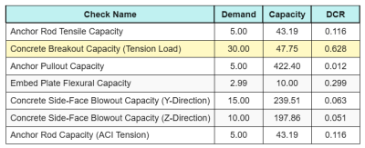
Εδώ είναι το αποτέλεσμα αναλογίες για όλους τους ελέγχους τάσης ACI:
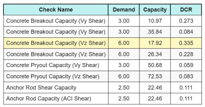
Και ιδού τα αποτελέσματα αναλογίες για όλους τους ελέγχους διάτμησης ACI:
Παίρνουμε την επιταγή με τη μεγαλύτερη αναλογία και τη συγκρίνουμε με τη μέγιστη αναλογία αλληλεπίδρασης χρησιμοποιώντας ACI 318-19 Εξ. 17.8.3.
\(ΕΓΩ_{int} = frac{Ν_{κάνω}}{\phi N_n} + \frac{V_{κάνω}}{\φι V_n} = frac{30}{47.749} + \frac{6}{17.921} = 0.96308\)
Από 0.96 < 1.2, ο έλεγχος αλληλεπίδρασης είναι επαρκής.
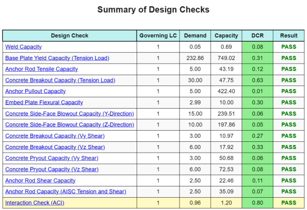
Περίληψη σχεδίου
ο Λογισμικό σχεδιασμού πλάκας βάσης SkyCIV Μπορεί να δημιουργήσει αυτόματα μια αναφορά υπολογισμού βήμα προς βήμα για αυτό το παράδειγμα σχεδιασμού. Παρέχει επίσης μια περίληψη των επιταγών που εκτελούνται και των προκύπτουσων αναλογιών τους, καθιστώντας τις πληροφορίες κατανοητές με μια ματιά. Παρακάτω είναι ένας πίνακας συνοπτικών δείγματος, που περιλαμβάνεται στην αναφορά.
Αναφορά δείγματος SkyCIV
Δείτε το επίπεδο λεπτομέρειας και σαφήνειας που μπορείτε να περιμένετε από μια αναφορά σχεδίασης πλάκας βάσης SkyCiv. Η αναφορά περιλαμβάνει όλους τους βασικούς ελέγχους σχεδιασμού, εξισώσεις, και τα αποτελέσματα παρουσιάζονται σε σαφή και ευανάγνωστη μορφή. Είναι πλήρως συμβατό με τα πρότυπα σχεδιασμού. Κάντε κλικ παρακάτω για να προβάλετε ένα δείγμα αναφοράς που δημιουργήθηκε με χρήση του SkyCiv Base Plate Calculator.
Αγορά λογισμικού πλάκας βάσης
Αγοράστε την πλήρη έκδοση της μονάδας σχεδιασμού πλάκας βάσης από μόνη της χωρίς άλλες ενότητες SkyCIV. Αυτό σας δίνει ένα πλήρες σύνολο αποτελεσμάτων για σχεδιασμό πλάκας βάσης, συμπεριλαμβανομένων λεπτομερών αναφορών και περισσότερων λειτουργιών.