In questo articolo, Ti guideremo attraverso il modo di determinare il terreno o le categorie di esposizione del lato rovesciato nella posizione del sito, che sono essenziali per il calcolo dei carichi del vento. Copriremo le procedure specifiche delineate in asce 7, NBCC 2015, e AS / NZS 1170.2 Per determinare le categorie del terreno e discutere di come si applicano a ciascun codice di riferimento disponibile nel generatore di carico Skyciv.
Asce 7-16/asce 7-22
discuteremo gli effetti della topografia sul carico del vento sulle strutture calcolando il fattore topografico Kzt utilizzando ASCE 7, La procedura per determinare la categoria di esposizione dell'esposizione controvento di una posizione del sito è discussa nella sezione 26.7, A seconda del terreno. In questo articolo, Per semplificare il riferimento, Useremo asce 7-16. Per ogni direzione della fonte del vento, Dovrebbe essere analizzato da due settori sopravento che si estendono ± 45 °.
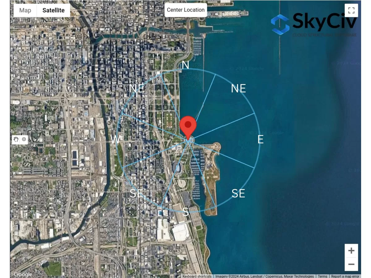
figura 1. Settori del terreno per ogni direzione della fonte del vento.
Per ogni settore, La categoria di rugosità superficiale deve essere verificata in base alla seguente definizione in base alla sezione 26.7.2 dell'ASCE 7-16:
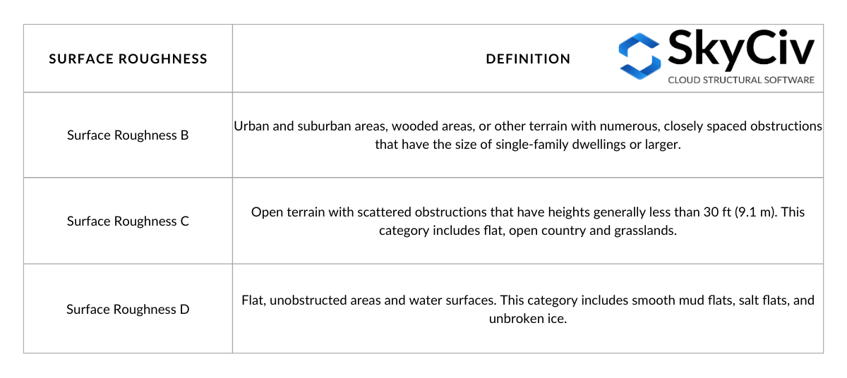
tavolo 1. Definizione della rugosità superficiale basata sulla sezione 26.7.2 dell'ASCE 7-16.
Dalla definizione di rugosità superficiale, Possiamo determinare la categoria di esposizione del terreno delimitato dal settore sopravento. La definizione per ciascuna categoria di esposizione è indicata nella sezione 26.7.3 dell'ASCE 7-16 come segue:
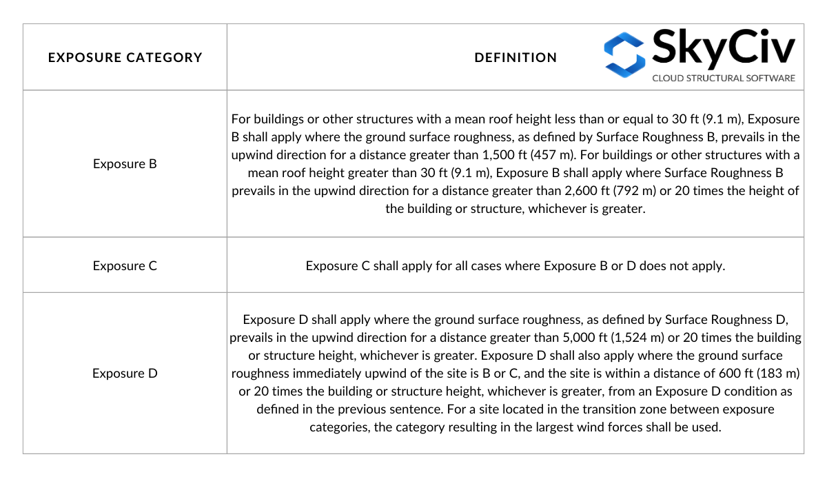
tavolo 2. Definizione della categoria di esposizione basata sulla sezione 26.7.3 dell'ASCE 7-16.
Il tavolo 2 può essere visualizzato attraverso le seguenti figure in base alla Figura C26.7-2:
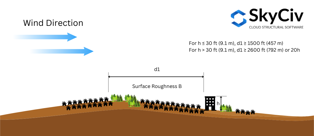
figura 2. Condizioni di rugosità superficiale sopravento richieste per l'esposizione b.
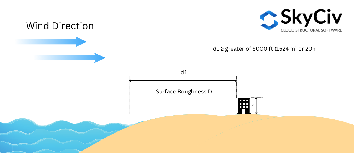
figura 3. Condizioni di rugosità superficiale sopravento richiesto per l'esposizione d – Astuccio 1.
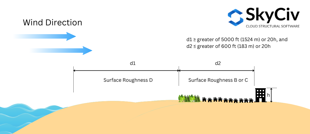
figura 4. Condizioni di rugosità superficiale sopravento richiesto per l'esposizione d – Astuccio 2.
La categoria di esposizione deve essere determinata per ciascuna direzione della fonte del vento. Utilizzando una posizione di esempio del sito – “1200 S DUSABLE LAGO SHORE DR DR, Chicago, IL 60605, Stati Uniti d'America”, Analizziamo questo per ogni direzione.
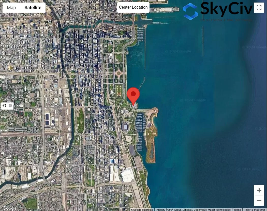
figura 4. Posizione del campione per l'analisi della categoria di esposizione.
Supponendo che l'altezza media del tetto della struttura sia 25 ft ( \( 20h = 500 ft \)), Utilizzeremo la seguente procedura per verificare la categoria di esposizione per ciascun settore:
Condizione 1. Determina se l'esposizione d usando la figura 3:
Usando la figura 3 – dove la distanza \( d_{1} \) è 5000 ft (1524 m), Dobbiamo verificare l'esposizione D, dove la rugosità superficiale d è dominante per il tutto 5000 Ft Stretch:
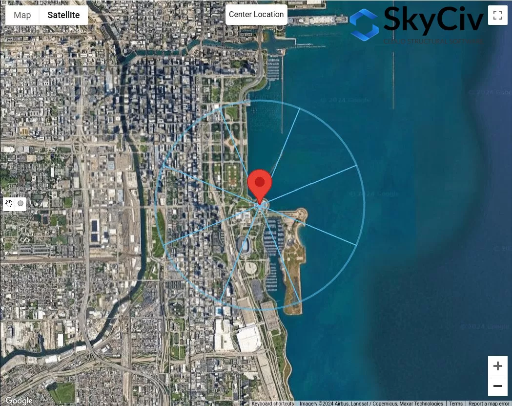
figura 5. Distanza offset di 5000 ft dalla posizione del sito per l'esposizione D Controllare utilizzando la figura 3.
Dalla figura 5, Possiamo già concludere che le direzioni della fonte del vento N, NATO, e E avere rugosità superficiale d per il tutto 5000 Ft Stretch. Pertanto, Queste indicazioni sulla fonte del vento sono Esposizione D.
Condizione 2. Determina se l'esposizione d usando la figura 2
Usando la figura 4 – dove la distanza \( d_{1} \) è 5000 ft (1524 m) e distanza \( d_{2} \) è uguale a 600 ft (183 m), Dobbiamo verificare l'esposizione D. Dalla figura 5, Questo può essere applicato solo per la direzione della fonte del vento da SE:
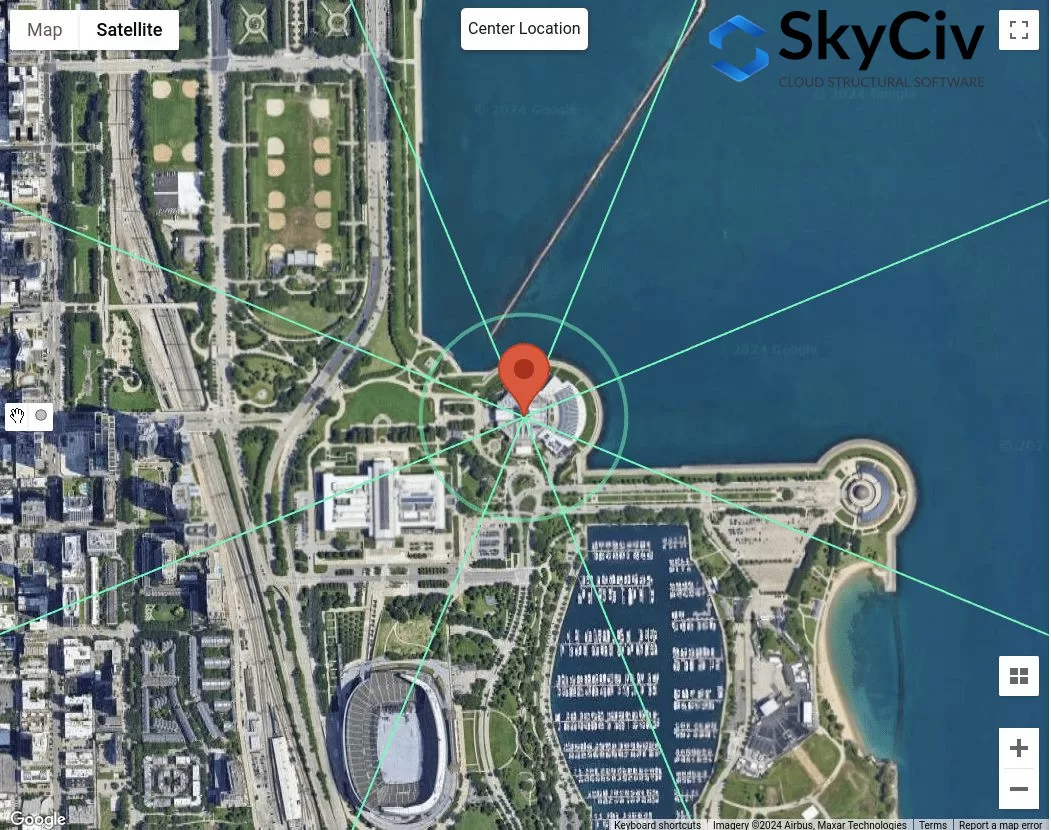
figura 6. Distanza di offset di 600 piedi e aggiuntivo 5000 ft dalla posizione del sito per l'esposizione D Controllare utilizzando la figura 4.
Per la direzione della fonte del vento SE, usando \( d_{2} = 600 ft \), Possiamo considerare che questa sezione è rugosità superficiale b. Tuttavia, per distanza \( d_{1} = 5000 ft \), La sezione non lo è 100% Rugosità superficiale d. Quindi, SE non dovrebbe essere considerato come esposizione d.
Condizione 3. Determina se l'esposizione B utilizzando la figura 1
Usando la figura 3 – dove la distanza \( d_{1} \) è 1500 ft (457 m) da \( h < 30 ft \), Dobbiamo verificare la presenza di esposizione B.
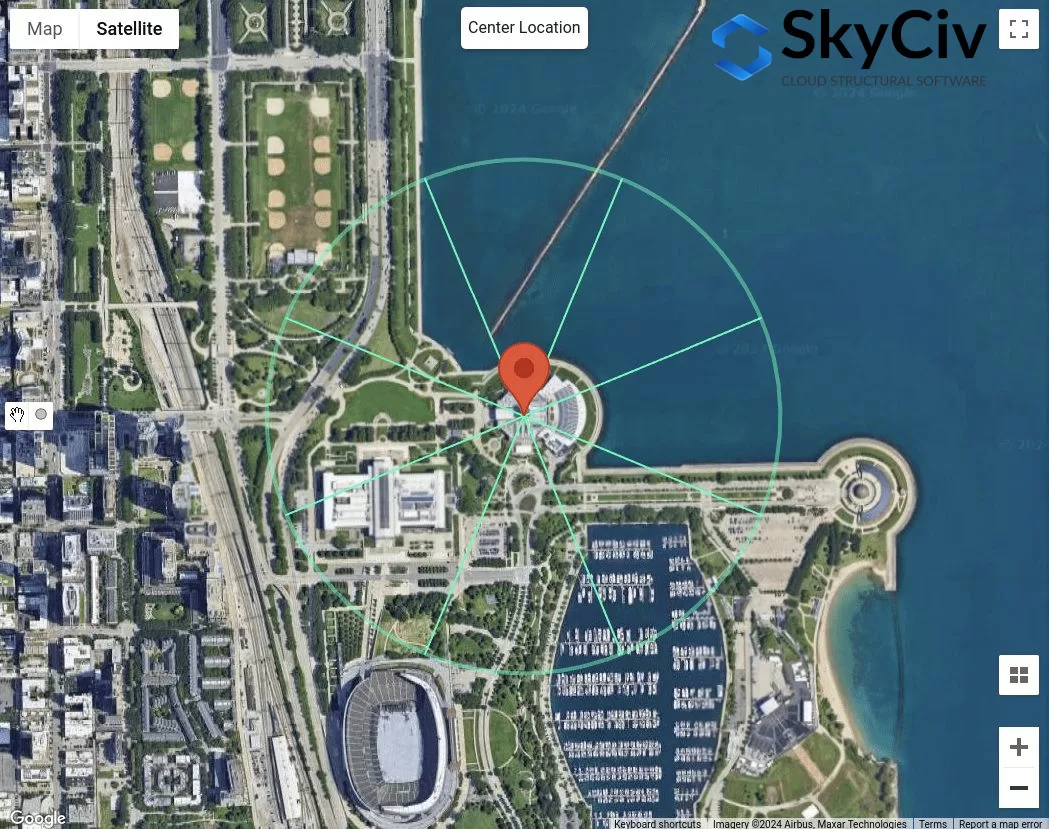
figura 7. Distanza offset di 1500 ft dalla posizione del sito per l'esposizione B Controllare utilizzando la figura 3.
Dalla figura 7, Possiamo determinare che per le direzioni della fonte del vento NW, W, SW, e S sono classificati come esposizione B poiché la rugosità superficiale per ciascun settore della direzione è la rugosità della superficie B.
Condizione 4. Se condizioni 1 per 3 non sono veri, perciò, Il terreno è l'esposizione c.
Pertanto, Per la direzione della fonte del vento SE, è classificato come categoria di esposizione C. In sintesi, Le categorie di esposizione per ciascuna direzione della fonte del vento sono mostrate in figura 8 sotto.
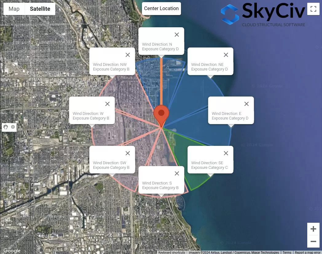
figura 8. Le categorie di esposizione per ogni direzione della fonte del vento.
Questi dati possono essere utilizzati per determinare quale sarà la direzione peggiore della fonte del vento come coefficienti di pressione di velocità \( K_{z} \), Fattore topografico \( K_{t} \), e fattore effetto raffica \( sol \) L'uso del calcolo dettagliato è influenzato dalla categoria di esposizione.
NBCC 2015/2020
Per NBCC 2015, La procedura per determinare la categoria di esposizione dell'esposizione controvento di una posizione del sito è discussa nella sezione 4.1.7.3(5), A seconda del terreno. Per ogni direzione della fonte del vento, Dovrebbe essere analizzato da due settori sopravento che si estendono ± 45 °.
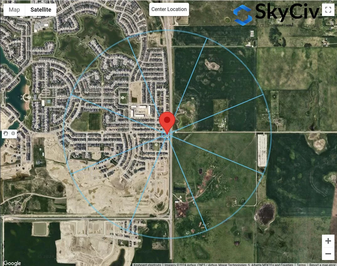
figura 9. Settori del terreno per ogni direzione della fonte del vento.
Per ogni settore, La categoria del terreno deve essere verificata in base alla seguente definizione in base alla sezione 4.1.7.3(5) della NBCC 2015:
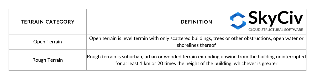
tavolo 3. Definizione delle categorie del terreno come definito nella sezione 4.1.7.3(5) della NBCC 2015.
Visualizzazione delle opzioni nella tabella 3:
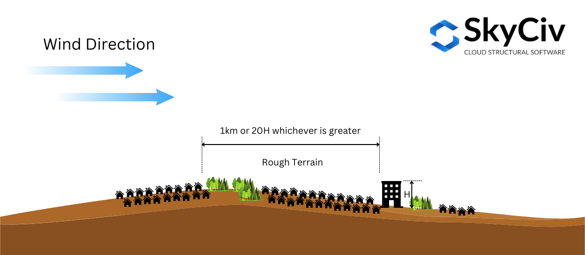
figura 10. Definizione di terreno rozzo come definito nella sezione 4.1.7.3(5) della NBCC 2015.
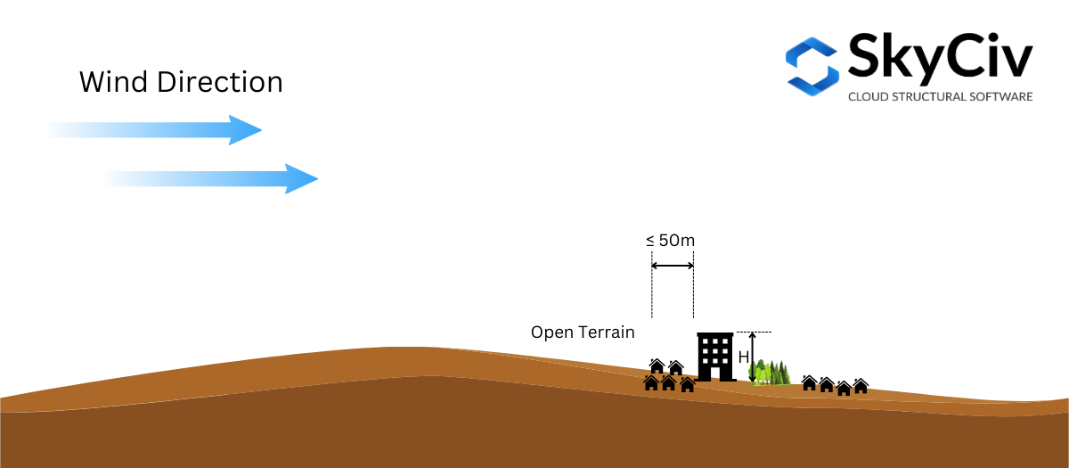
figura 10. Definizione del terreno aperto come definito nella sezione 4.1.7.3(5) della NBCC 2015.
In base alla sezione 4.1.7.3(5) della NBCC 2015, è autorizzato a interpolare il Fattore di esposizione \( C_{e} \) in terreno intermedio. Se la distanza del terreno grezzo dalla posizione della struttura è maggiore o uguale a 1 km o 20 volte l'altezza della struttura, qualunque sia maggiore, il terreno può essere considerato come Terreno accidentato, e se la distanza è inferiore a 50 m, è considerato come Terreno aperto. Altrimenti, il fattore di esposizione \( C_{e} \) come da Sez 4.1.7.3(5) sarà calcolato dai valori al contorno. Questo può essere visualizzato in figura 11 sotto.
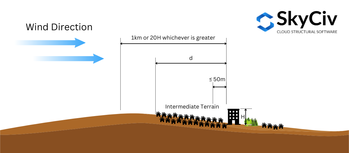
figura 11. Definizione di terreno intermedio come definito nella sezione 4.1.7.3(5) della NBCC 2015.
Per illustrare ulteriormente questo, Usiamo una posizione di esempio del sito – “657 Masters Rd SE, Calgary, AB T3M 2B6, Canada,” Supponendo l'altezza della struttura \( H \) è 25 m ( \( 20H = 500 m \)).
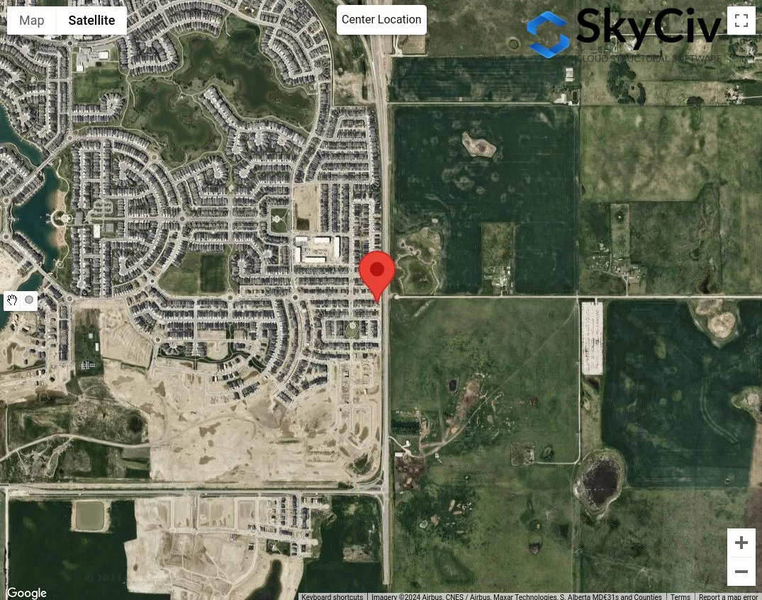
figura 12. Posizione del campione per l'analisi della categoria del terreno.
Il primo passo è classificare le ovvie categorie di terreni approssimativi e aperti per ciascuna direzione della fonte del vento. Possiamo disegnare 50 m e max di 1 km o \( 20 H \) raggio dalla posizione del sito.
figura 13. Distanza di offset di 50 m e 1 km per determinare la categoria del terreno in base alla tabella 1 Definizioni.
Dalla figura 13, Possiamo dire che le direzioni della fonte del vento NATO, E, e SE sono classificati come Terreno aperto Poiché la lunghezza del terreno ruvido per ogni direzione è inferiore a 50 m dalla posizione del sito. Inoltre, Per le indicazioni della fonte del vento W e NW può essere classificato come terreno accidentato poiché la lunghezza del terreno approssimativo per queste direzioni è maggiore di 1 km. Per la direzione della fonte del vento N, Possiamo supporre in modo conservativo che il terreno aperto sia dominante in questa direzione. Per il resto, S e sw, Possiamo concludere che si tratta di un terreno intermedio e dovremo misurare la distanza del terreno accidentato dalla posizione del sito.
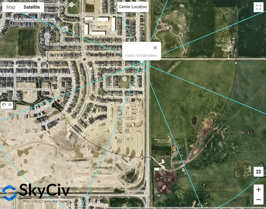
figura 14. Lunghezza approssimativa del terreno approssimativo misurata dalla posizione del sito per la direzione della sorgente del vento SW pari a 574 m.
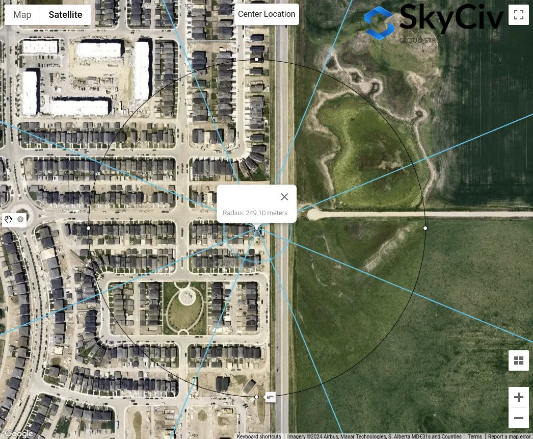
figura 15. Lunghezza approssimativa del terreno approssimativo misurata dalla posizione del sito per la direzione della fonte del vento uguale a 249 m.
Dall'analisi sopra, Sicuramente le direzioni della fonte del vento con terreno aperto produrranno sicuramente i valori conservativi. Tuttavia, Se tutte le direzioni della fonte del vento sono classificate in terreno intermedio, La procedura sopra è come è possibile determinare la categoria del terreno appropriato per ciascuna direzione.
AS / NZS 1170.2 (2021)
Per AS/NZS 1170.2, La stessa procedura con i riferimenti di cui sopra si applica nel determinare la categoria del terreno dell'esposizione ribalta di una posizione del sito. Questo è discusso nella sezione 4.2 di AS / NZS 1170.2 (2021). Per ogni direzione della fonte del vento, Dovrebbe essere analizzato da due settori sopravento che si estendono ± 45 °. La definizione di ogni categoria del terreno è mostrata di seguito in base alla sezione 4.2.1 di AS / NZS 1170.2 (2021):
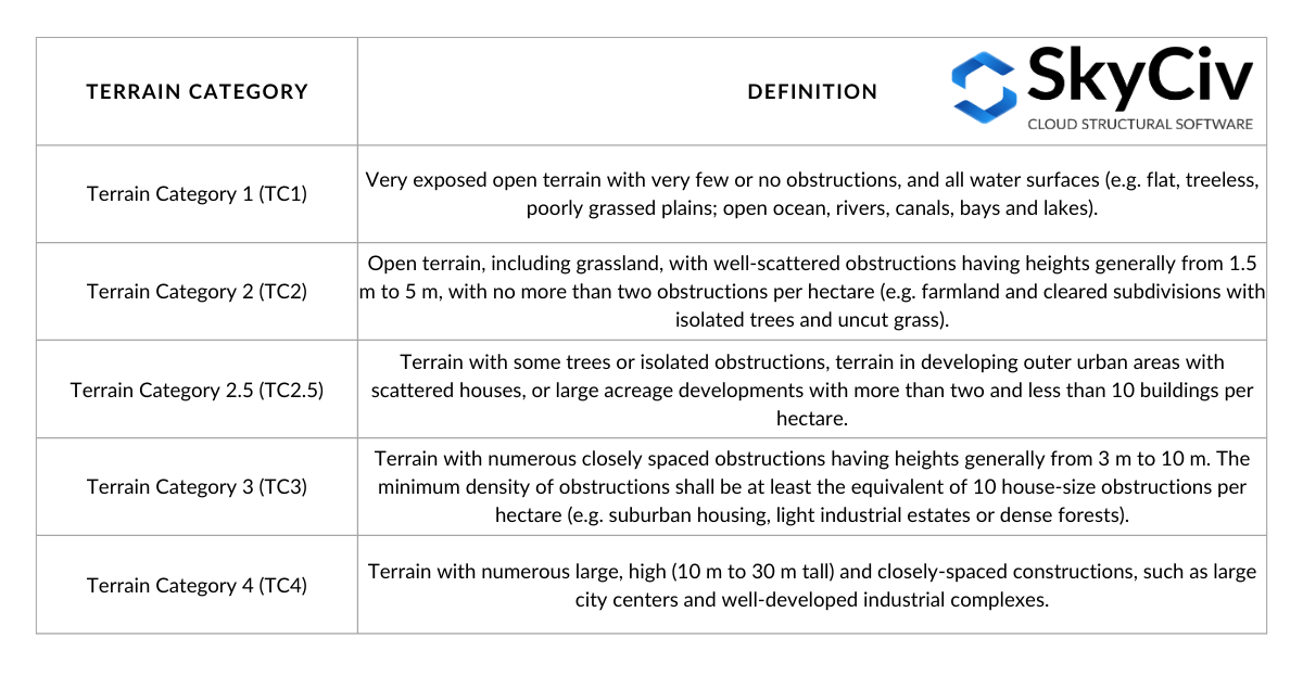
tavolo 4. Definizione delle categorie del terreno come definito nella sezione 4.2.1 di AS / NZS 1170.2 (2021).
Nel determinare la categoria del terreno per una direzione, una distanza in ritardo pari a \( 20 z \) Dalla posizione della struttura deve essere trascurata. Da questo punto, una distanza di offset (distanza media) di 500 m o \( 40 z), qualunque sia più grande, deve essere usato come mostrato nella figura 16 sotto. La \( z \) Il valore è uguale all'altezza media del tetto, \( h \), quando è inferiore o uguale a 25 m. È possibile che all'interno di questa distanza in media ha più categorie di terreni, e come tale, L'interpolazione lineare di deve essere utilizzata per determinare il \( M_{z,gatto} \) valori, A seconda della lunghezza di ogni categoria del terreno, come illustrato in Figura 4.1 di AS / NZS 1170.2 (2021). In questo articolo, Considereremo solo una categoria di terreni omogenei entro la distanza media.
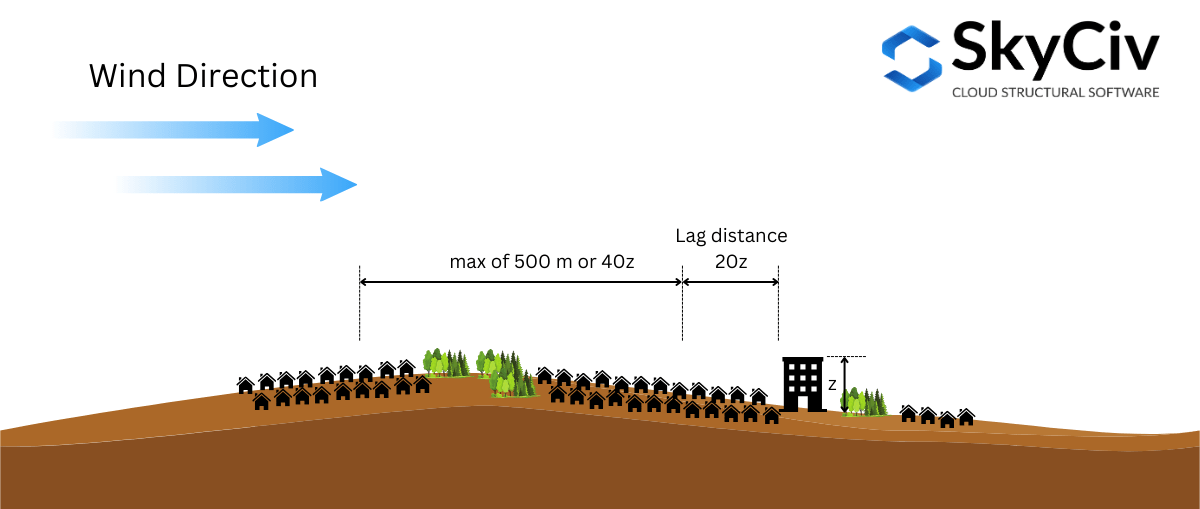
figura 16. Illustrazione delle distanze utilizzate nella categoria del terreno determinante basato su AS/NZ 1170.2 (2021).
Per illustrare ulteriormente questo, Usiamo una posizione di esempio del sito – Lat: 32° 43’46″S lng: 151° 31’47″E – Supponendo l'altezza media del tetto \( h \) è 10 m ( dove \( 20z = 20h = 200 m \) e \( 40z = 400 m \)).
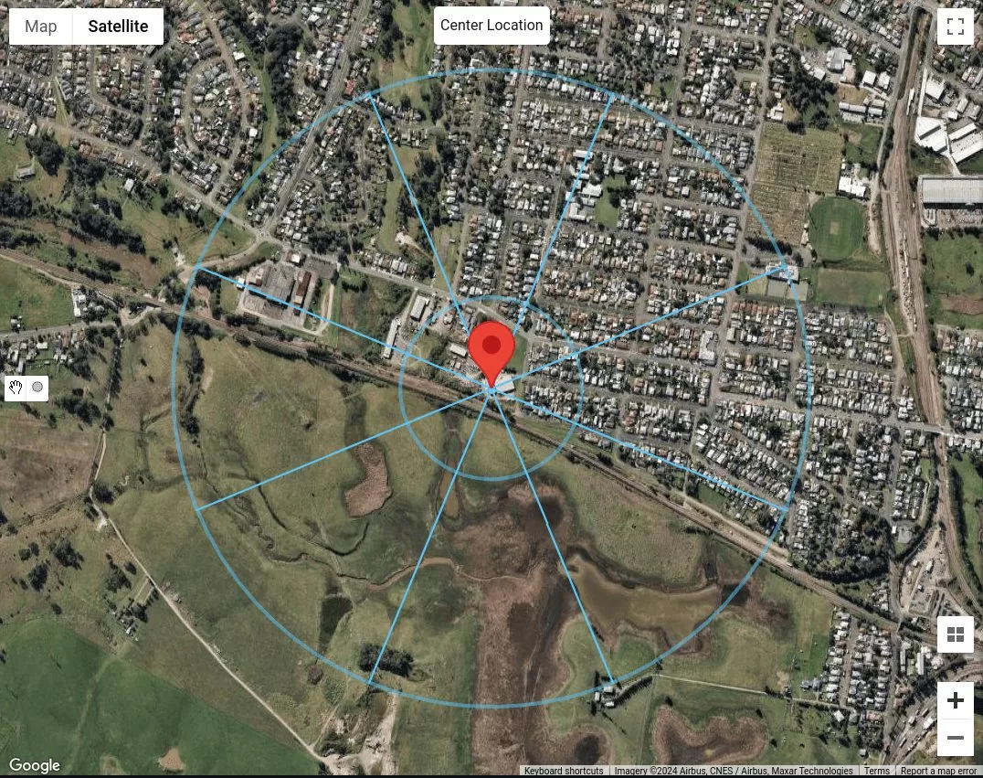
figura 17. La posizione del sito con distanza in ritardo pari a 200 M e una distanza mediana uguale a 500 M per ogni direzione della fonte del vento.
Dal momento che dobbiamo considerare solo la categoria del terreno come omogenea durante l'intero 500 m o \( 40z \) distanza, Possiamo già classificare ogni direzione della fonte del vento. Supponendo gli edifici su N, Ne ed e, sono edifici che sono 5 per 10 m di altezza, Possiamo classificarli con la categoria del terreno 3 (TC3) come mostrato nella tabella 4. Per le indicazioni della fonte del vento SE, S, SW, e w, Dal momento che queste sono pianure di erba senza ostacoli, Possiamo classificarli come categoria del terreno 1 (TC1). Infine, Per la direzione della fonte del vento NW, Possiamo dedurre che ce ne sono più di due ma meno di 10 edifici per ettaro, con case sparse. Pertanto, Possiamo classificarlo come categoria del terreno 2.5 (TC2.5).
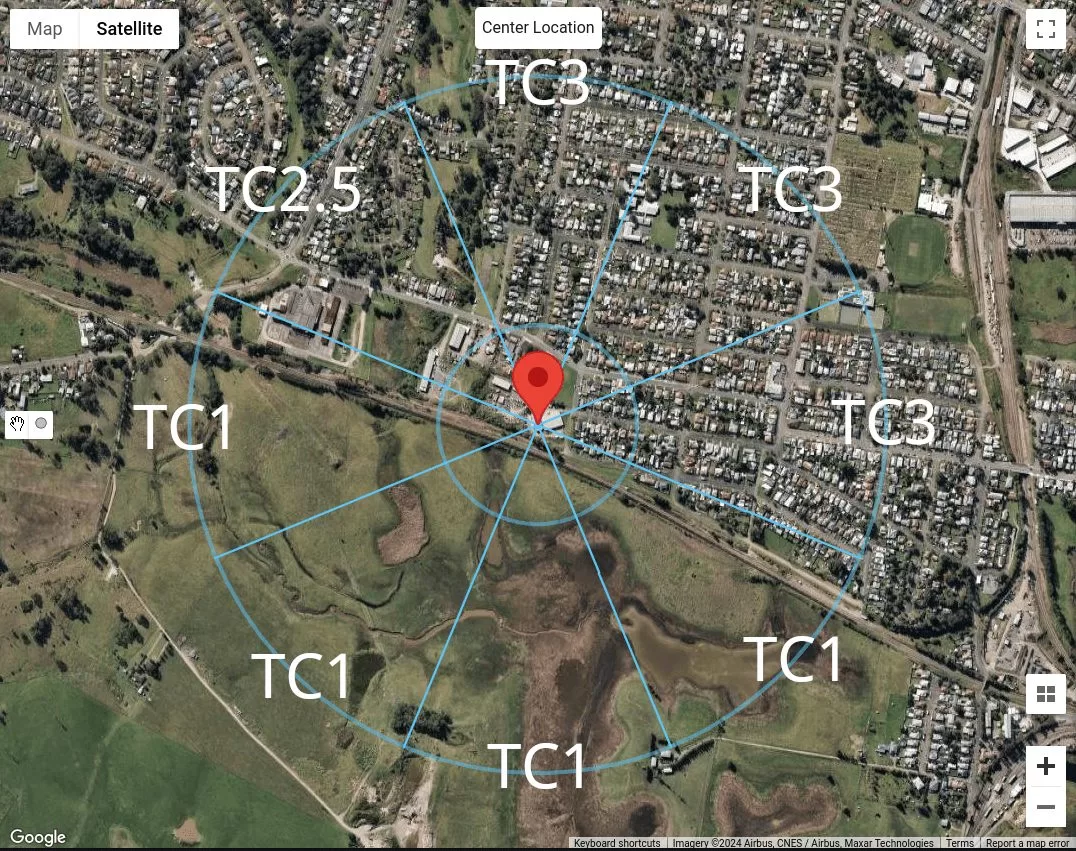
figura 18. Riepilogo della classificazione delle categorie del terreno per ciascuna direzione della fonte del vento per la nostra posizione del campione.
Utilizzo del generatore di carico SkyCiv
Nella versione del generatore di carico Skyciv v4.7.0, Vengono introdotti nuovi strumenti di mappa – Misurare la distanza e Raggi di distanza utensili.
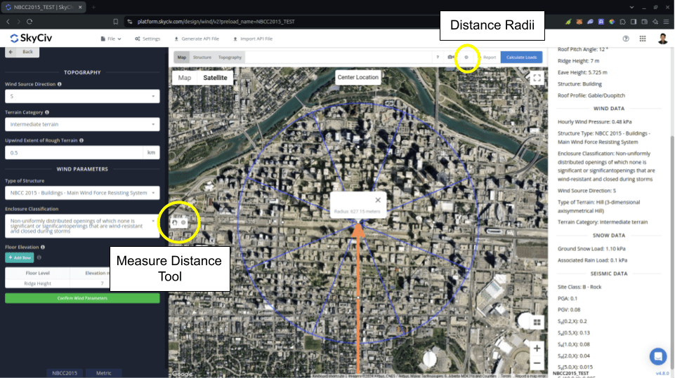
figura 19. Strumenti di misurazione della distanza introdotti in SkyCiv Load Generator.
La Misurare la distanza lo strumento viene utilizzato per generare un cerchio da un punto cliccato sulla mappa e mostrarne il raggio in metri. Per di qua, è possibile misurare le distanze dalla posizione analizzata in determinate posizioni. Questo può essere utilizzato nella misurazione in NBCC 2015 per il Estensione del terreno accidentato controvento usato nel calcolo Fattore di esposizione \( C_{e} \). Facendo clic sul cerchio generato lo cancellerà dalla mappa.
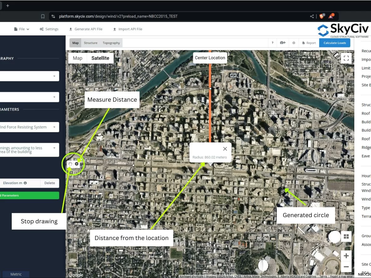
figura 20. Misura lo strumento a distanza che crea un offset dalla posizione e mostra la distanza raggio/offset dal centro introdotto al generatore di carico Skyciv.
D'altro canto, il Raggi di distanza viene introdotto in modo che gli utenti possano disegnare cerchi con distanze specifiche dalla posizione per ciascuna categoria di sorgente eolica. È un pulsante a attiva a levetta per mostrare o nascondere i raggi di distanza sulla mappa, con la posizione del sito come centro dei cerchi.
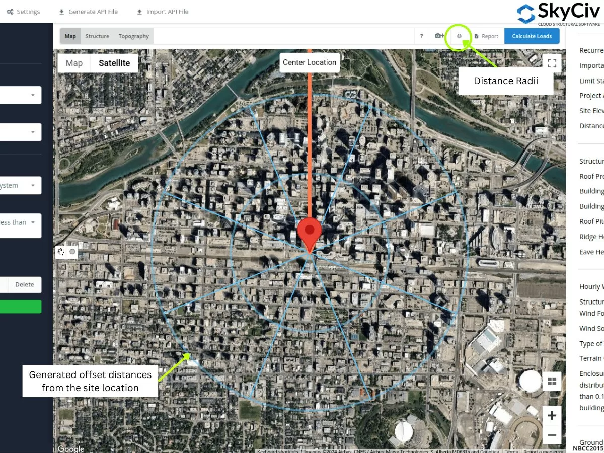
figura 21. Strumento RADII a distanza che ha specificato le distanze di offset dalla posizione del sito introdotta al generatore di carico Skyciv.
I valori RADII possono essere modificati all'apertura delle impostazioni.
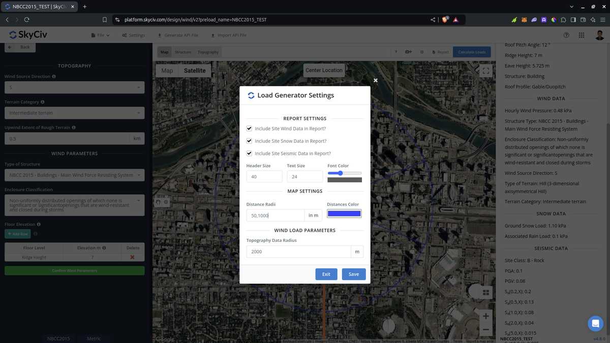
figura 22. Opzione nelle impostazioni per modificare le distanze per lo strumento Radii distanza in SkyCiv Load Generator.
Si noti che gli utenti devono modificare i valori della distanza in quanto non vengono calcolati automaticamente dal software. Usando questo per asce 7 e NBCC, Deve essere adottata la peggiore della categoria di esposizione o terreno per ciascuna direzione della fonte del vento. Per quanto riguarda l'utilizzo in AS/NZS 1170.2 (2021), Il software non utilizza i valori RADII per calcolare per la media \( M_{z,gatto} \) valori. Anziché, La distanza di media viene utilizzata come intervallo applicabile in cui possiamo assegnare una categoria di terreno omogeneo, Adottare la peggior categoria per ogni direzione della fonte del vento.
Dalle sezioni discusse sopra, È possibile utilizzare questi nuovi strumenti per determinare le categorie di esposizione o terreno per ciascuna direzione della fonte del vento. Le procedure sopra possono darti una rapida classificazione del terreno di ciascuna direzione della fonte del vento. Utilizzo di strumenti GIS e AI, È possibile verificare ulteriormente i criteri che abbiamo usato sopra per ciascuna direzione della fonte del vento e può ottenere un risultato migliore ed efficiente.

Ingegnere strutturale, Sviluppo del prodotto
MS Ingegneria Civile
Riferimenti:
- Carichi minimi di progettazione per edifici e altre strutture. (2017). ASCE/SEI 7-16. American Society of Civil Engineers.
- Consiglio nazionale delle ricerche del Canada. (2015). National Building Code of Canada, 2015. Consiglio nazionale delle ricerche del Canada.
- Standard Australia (2021), Azioni di progettazione strutturale. Parte 2 Azioni del vento, Standard Australian/New Zealand AS/NZS1170.2:2021, Standard Australia, Sydney, NSW, Australia.
- Posizione della struttura e direzione della sorgente del vento corrispondente