Παράδειγμα σχεδίασης πλάκας βάσης με χρήση CSA S16:19 και CSA A23.3:19
Προβληματική δήλωση
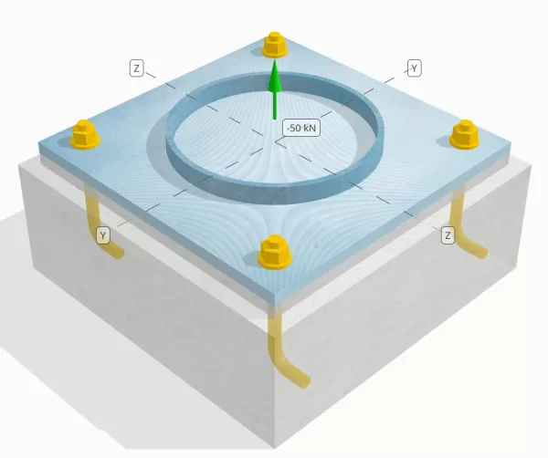
Προσδιορίστε εάν η σχεδιασμένη σύνδεση στήλης-πλάκας βάσης είναι επαρκής για φορτίο εφελκυσμού 50 kN.
Δεδομένα
Στήλη:
Ενότητα στήλης: HS324X9.5
Επιφάνεια στήλης: 9410 χιλ2
Υλικό στήλης: 230σολ
Πλάκα βάσης:
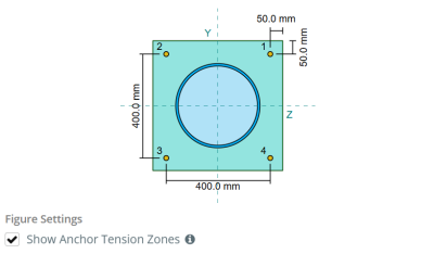
Διαστάσεις πλάκας βάσης: 500 mm x 500 χιλ
Πάχος πλάκας βάσης: 20 χιλ
Υλικό πλάκας βάσης: 230σολ
Πηκτώ:
Πάχος ενέματα: 20 χιλ
Σκυρόδεμα:
Διαστάσεις σκυροδέματος: 550 mm x 550 χιλ
Πάχος σκυροδέματος: 200 χιλ
Σκυρόδεμα: 20.68 MPa
Ραγισμένα ή αδιευκρίνιστα: Ραγισμένος
Άγκυρες:
Διάμετρος άγκυρας: 19.1 χιλ
Αποτελεσματικό μήκος ενσωμάτωσης: 130.0 χιλ
Μήκος γάντζου: 60χιλ
Απόσταση μετατόπισης άγκυρας από την όψη της στήλης: 120.84 χιλ
Συγκολλήσεις:
Τύπος συγκόλλησης: CJP
Η ταξινόμηση μετάλλων πλήρωσης: E43xx
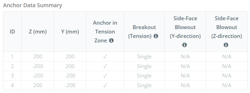
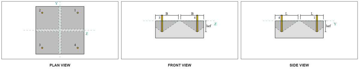
Δεδομένα αγκυροβόλησης (από Υπολογιστής Skyciv):
Μοντέλο στο δωρεάν εργαλείο SkyCiv
Μοντελοποιήστε το παραπάνω σχέδιο πλάκας βάσης χρησιμοποιώντας το δωρεάν διαδικτυακό μας εργαλείο σήμερα! Δεν απαιτείται εγγραφή.
Ορισμοί
Διαδρομή φόρτωσης:
Όταν μια πλάκα βάσης υποβάλλεται σε ανύψωση (εντάσεως) δυνάμεις, Αυτές οι δυνάμεις μεταφέρονται στις ράβδους άγκυρας, που με τη σειρά τους προκαλούν στιγμές κάμψης στην πλάκα βάσης. Η δράση κάμψης μπορεί να απεικονιστεί ως κάμψη που συμβαίνουν γύρω από τις φλάντζες ή τον ιστό της ενότητας στήλης, ανάλογα με το πού τοποθετούνται οι άγκυρες.
Στο Λογισμικό σχεδιασμού πλάκας βάσης SkyCIV, μόνο άγκυρες που βρίσκονται μέσα στο ζώνη τάσης άγκυρας θεωρούνται αποτελεσματικοί στην αντιστάθμιση της ανύψωσης. Αυτή η ζώνη περιλαμβάνει συνήθως περιοχές κοντά στις φλάντζες της στήλης ή στο διαδίκτυο. Στην περίπτωση του α κυκλική στήλη, η ζώνη τάνυσης αγκύρωσης περιλαμβάνει ολόκληρη την περιοχή έξω από την περίμετρο της στήλης. Οι άγκυρες εκτός αυτής της ζώνης δεν συμβάλλουν στην αντίσταση στην ένταση και αποκλείονται από τους υπολογισμούς ανύψωσης.
Για να προσδιορίσετε την αποτελεσματική περιοχή της πλάκας βάσης που αντιστέκεται στην κάμψη, ένα 45-διασπορά υποτίθεται από την κεντρική γραμμή κάθε ράβδου αγκύρωσης προς την επιφάνεια της στήλης. Αυτή η διασπορά ορίζει το αποτελεσματικό μήκος συγκόλλησης και βοηθά στη δημιουργία του αποτελεσματικό πλάτος κάμψης του πιάτου.
Η υπόθεση απλοποιεί την ανάλυση της πλάκας βάσης προσεγγίζοντας τον τρόπο με τον οποίο εξαπλώνεται η δύναμη ανύψωσης μέσω της πλάκας.
Ομάδες άγκυρας:
ο Λογισμικό σχεδιασμού πλάκας βάσης SkyCIV Περιλαμβάνει ένα διαισθητικό χαρακτηριστικό που προσδιορίζει ποιες άγκυρες αποτελούν μέρος μιας ομάδας αγκύρωσης για αξιολόγηση ξέσπασμα σκυροδέματος και έκρηξη από σκυρόδεμα στο πλάι του προσώπου αποτυχία.
Ενα ομάδα άγκυρας Αποτελείται από πολλαπλές άγκυρες με παρόμοια αποτελεσματικά βάθη ενσωμάτωσης και απόσταση, και είναι αρκετά κοντά ώστε τους Οι προβλεπόμενες περιοχές αντίστασης επικαλύπτονται. Όταν ομαδοποιούνται άγκυρες, Οι ικανότητές τους συνδυάζονται για να αντισταθούν στη συνολική δύναμη έντασης που εφαρμόζεται στην ομάδα.
Οι άγκυρες που δεν πληρούν τα κριτήρια ομαδοποίησης αντιμετωπίζονται ως άγκυρες. Σε αυτήν την περίπτωση, Μόνο η δύναμη τάσης στην ατομική άγκυρα ελέγχεται από τη δική της αποτελεσματική περιοχή αντίστασης.
Υπολογισμοί βήμα προς βήμα
Ελεγχος #1: Υπολογίστε τη χωρητικότητα συγκόλλησης
Να ξεκινήσω, πρέπει να υπολογίσουμε το φορτίο ανά άγκυρα και να προσδιορίσουμε το πραγματικό μήκος συγκόλλησης για κάθε άγκυρα. ο αποτελεσματικό μήκος συγκόλλησης βασίζεται σε α 45° γραμμή διασποράς τραβηγμένο από το κέντρο της άγκυρας προς την όψη της στήλης. Εάν αυτή η γραμμή 45° δεν τέμνει τη στήλη, ο εφαπτομενικά σημεία χρησιμοποιούνται αντ' αυτού. Επιπροσθέτως, εάν οι άγκυρες απέχουν πολύ κοντά, το αποτελεσματικό μήκος συγκόλλησης μειώνεται για να αποφευχθεί η επικάλυψη. Τελικά, το άθροισμα όλων των ενεργών μηκών συγκόλλησης δεν πρέπει να υπερβαίνει το πραγματικό διαθέσιμο μήκος συγκόλλησης κατά μήκος της περιφέρειας της στήλης.
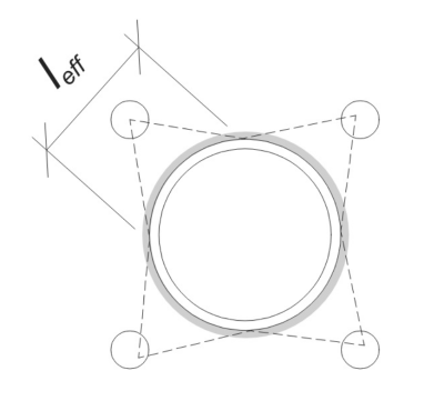
Ας το εφαρμόσουμε στο παράδειγμά μας. Με βάση τη δεδομένη γεωμετρία, η γραμμή 45° από την άγκυρα δεν τέμνει τη στήλη. Σαν άποτέλεσμα, Αντ' αυτού χρησιμοποιείται το μήκος τόξου μεταξύ των εφαπτομένων σημείων. Αυτό το μήκος τόξου πρέπει επίσης να λαμβάνει υπόψη τυχόν γειτονικές άγκυρες, αφαιρώντας τυχόν επικαλυπτόμενα τμήματα για να αποφευχθεί η διπλή καταμέτρηση. Το υπολογισμένο μήκος τόξου είναι:
\(
μεγάλο_{\κείμενο{τόξο}} = 254.47 \, \κείμενο{χιλ}
\)
Αυτός ο υπολογισμός μήκους τόξου είναι πλήρως αυτοματοποιημένος στο λογισμικό σχεδίασης πλακών βάσης SkyCiv, αλλά μπορεί επίσης να εκτελεστεί χειροκίνητα χρησιμοποιώντας τριγωνομετρικές μεθόδους. Μπορείτε να δοκιμάσετε το δωρεάν εργαλείο από αυτόν τον σύνδεσμο.
Λαμβάνοντας υπόψη το διαθέσιμο μήκος συγκόλλησης κατά μήκος της περιφέρειας της στήλης, τον τελικό αποτελεσματικό μήκος συγκόλλησης είναι:
\(
μεγάλο_{\κείμενο{εφ}} = min αριστερά( μεγάλο_{\κείμενο{τόξο}}, \frac{\pi d_{\κείμενο{διάσελο}}}{n_{ένα,τ}} \σωστά) = min αριστερά( 254.47 \, \κείμενο{χιλ}, \frac{\pi φορές 324 \, \κείμενο{χιλ}}{4} \σωστά) = 254.47 \, \κείμενο{χιλ}
\)
Επόμενο, ας υπολογίσουμε το φορτίο ανά άγκυρα. Για ένα δεδομένο σύνολο τεσσάρων (4) άγκυρες, Το φορτίο ανά άγκυρα είναι:
\(
T_{εσύ,\κείμενο{άγκυρα}} = frac{N_x}{n_{ένα,τ}} = frac{50 \, \κείμενο{ΚΝ}}{4} = 12.5 \, \κείμενο{ΚΝ}
\)
Χρήση του υπολογισμένου αποτελεσματικού μήκους συγκόλλησης, μπορούμε τώρα να υπολογίσουμε το απαιτούμενη δύναμη ανά μονάδα μήκους ενεργώντας στη συγκόλληση.
\(
v_f = frac{T_{εσύ,\κείμενο{άγκυρα}}}{μεγάλο_{\κείμενο{εφ}}} = frac{12.5 \, \κείμενο{ΚΝ}}{254.47 \, \κείμενο{χιλ}} = 0.049122 \, \κείμενο{kN / mm}
\)
Τώρα, αναφερόμαστε CSA S16:19 Ρήτρα 13.13.3.1 να υπολογίσει το συντελεστής αντίστασης της πλήρους διείσδυσης της άρθρωσης (CJP) συγκόλληση. Αυτό απαιτεί την αντίσταση του βασικού μετάλλου, εκφράζεται σε ισχύ ανά μονάδα μήκους, τόσο για τη στήλη όσο και για τα υλικά της πλάκας βάσης.
\(
v_{ρ,\κείμενο{bm}} = phi αριστερά( \min left( ΦΑ_{και,\κείμενο{διάσελο}} αυτό είναι ένα πολύ σημαντικό στάδιο στο σχεδιασμό ενός τοίχου αντιστήριξης, καθώς η μη αντιστοίχιση των σωστών αναλογικών διαστάσεων από την αρχή σε κάθε στοιχείο μπορεί να οδηγήσει στην ανάγκη πολλών επαναλήψεων για να συμμορφωθεί ο τοίχος αντιστήριξης με τις απαιτήσεις ευστάθειας ή υπερμεγέθη σύστημα που πληροί όλες τις απαιτήσεις, αλλά χρησιμοποιεί πολύ περισσότερο υλικό από το θεωρητικό ελάχιστο{\κείμενο{διάσελο}}, ΦΑ_{και,\κείμενο{bp}} αυτό είναι ένα πολύ σημαντικό στάδιο στο σχεδιασμό ενός τοίχου αντιστήριξης, καθώς η μη αντιστοίχιση των σωστών αναλογικών διαστάσεων από την αρχή σε κάθε στοιχείο μπορεί να οδηγήσει στην ανάγκη πολλών επαναλήψεων για να συμμορφωθεί ο τοίχος αντιστήριξης με τις απαιτήσεις ευστάθειας ή υπερμεγέθη σύστημα που πληροί όλες τις απαιτήσεις, αλλά χρησιμοποιεί πολύ περισσότερο υλικό από το θεωρητικό ελάχιστο{\κείμενο{bp}} \σωστά) \σωστά)
\)
\(
v_{ρ,\κείμενο{bm}} = 0.9 \φορές αριστερά( \min left( 230 \, \κείμενο{MPa} \φορές 9.53 \, \κείμενο{χιλ}, 230 \, \κείμενο{MPa} \φορές 20 \, \κείμενο{χιλ} \σωστά) \σωστά) = 1.9727 \, \κείμενο{kN / mm}
\)
Από 0.049122 kN / mm < 1.9727 kN / mm, Η χωρητικότητα συγκόλλησης είναι επαρκής.
Ελεγχος #2: Υπολογίστε τη χωρητικότητα κάμψης πλάκας βάσης λόγω φορτίου τάσης
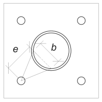
Χρησιμοποιώντας το φορτίο ανά άγκυρα και το απόσταση μετατόπισης από το κέντρο της άγκυρας μέχρι την όψη της στήλης, Η στιγμή που εφαρμόζεται στην πλάκα βάσης μπορεί να υπολογιστεί χρησιμοποιώντας ένα υποστήριγμα υπόθεση. Για κυκλική στήλη, η εκκεντρότητα του φορτίου προσδιορίζεται λαμβάνοντας υπόψη την οβελία του συγκολλημένου τόξου, και μπορεί να υπολογιστεί ως εξής:
\(
μι_{\κείμενο{σωλήνας}} = d_o + r_{\κείμενο{διάσελο}} \αριστερά( 1 – \cos αριστερά( \frac{μεγάλο_{\κείμενο{εφ}}}{2 r_{\κείμενο{διάσελο}}} \σωστά) \σωστά)
\)
\(
μι_{\κείμενο{σωλήνας}} = 120.84 \, \κείμενο{χιλ} + 162 \, \κείμενο{χιλ} \φορές αριστερά( 1 – \cos αριστερά( \frac{254.47 \, \κείμενο{χιλ}}{2 \φορές 162 \, \κείμενο{χιλ}} \σωστά) \σωστά) = 168.29 \, \κείμενο{χιλ}
\)
Η επαγόμενη ροπή υπολογίζεται ως:
\(
M_f = T_{εσύ,\κείμενο{άγκυρα}} μι_{\κείμενο{σωλήνας}} = 12.5 \, \κείμενο{ΚΝ} \φορές 168.29 \, \κείμενο{χιλ} = 2103.6 \, \κείμενο{ΚΝ} \cdot text{χιλ}
\)
Επόμενο, θα καθορίσουμε το πλάτος κάμψης της πλάκας βάσης. Για αυτό, χρησιμοποιούμε το μήκος χορδής που αντιστοιχεί στο ενεργό τόξο συγκόλλησης.
\(
\θήτα_{\κείμενο{rad}} = frac{μεγάλο_{\κείμενο{εφ}}}{0.5 ρε_{\κείμενο{διάσελο}}} = frac{254.47 \, \κείμενο{χιλ}}{0.5 \φορές 324 \, \κείμενο{χιλ}} = 1.5708
\)
\(
b = d_{\κείμενο{διάσελο}} \αριστερά( \αμαρτία αριστερά( \frac{\θήτα_{\κείμενο{rad}}}{2} \σωστά) \σωστά) = 324 \, \κείμενο{χιλ} \φορές αριστερά( \αμαρτία αριστερά( \frac{1.5708}{2} \σωστά) \σωστά) = 229.1 \, \κείμενο{χιλ}
\)
Τελικά, Μπορούμε να υπολογίσουμε το παράγοντας αντίσταση κάμψης της πλάκας βάσης χρησιμοποιώντας CSA S16:19 Ρήτρα 13.5.
\(
M_r = phi F_{και,\κείμενο{bp}} Z_{\κείμενο{εφ}} = 0.9 \φορές 230 \, \κείμενο{MPa} \φορές 22910 \, \κείμενο{χιλ}^3 = 4742.4 \, \κείμενο{ΚΝ} \cdot text{χιλ}
\)
Οπου,
\(
Z_{\κείμενο{εφ}} = frac{σι (αυτό είναι ένα πολύ σημαντικό στάδιο στο σχεδιασμό ενός τοίχου αντιστήριξης, καθώς η μη αντιστοίχιση των σωστών αναλογικών διαστάσεων από την αρχή σε κάθε στοιχείο μπορεί να οδηγήσει στην ανάγκη πολλών επαναλήψεων για να συμμορφωθεί ο τοίχος αντιστήριξης με τις απαιτήσεις ευστάθειας ή υπερμεγέθη σύστημα που πληροί όλες τις απαιτήσεις, αλλά χρησιμοποιεί πολύ περισσότερο υλικό από το θεωρητικό ελάχιστο{\κείμενο{bp}})^ 2}{4} = frac{229.1 \, \κείμενο{χιλ} \φορές (20 \, \κείμενο{χιλ})^ 2}{4} = 22910 \, \κείμενο{χιλ}^ 3
\)
Από 2103.6 kN-mm < 4742.4 kN-mm, Η ικανότητα απόδοσης της κάμψης της πλάκας βάσης είναι επαρκής.
Ελεγχος #3: Υπολογίστε την ικανότητα εφελκυσμού της ράβδου άγκυρας
Για να αξιολογηθεί η ικανότητα εφελκυσμού της ράβδου αγκύρωσης, αναφερόμαστε στο CSA A23.3:19 Ρήτρα D.6.1.2 και CSA S16:19 Ρήτρα 25.3.2.1.
Πρώτα, καθορίζουμε το συγκεκριμένη αντοχή εφελκυσμού του χάλυβα άγκυρας. Αυτή είναι η χαμηλότερη τιμή που επιτρέπεται από CSA A23.3:19 Ρήτρα Δ.6.1.2.
\(
φά_{\κείμενο{Γιούτα}} = min αριστερά( ΦΑ_{εσύ,\κείμενο{Α.Κ.}}, 1.9 ΦΑ_{και,\κείμενο{Α.Κ.}}, 860 \σωστά) = min αριστερά( 400 \, \κείμενο{MPa}, 1.9 \φορές 248.2 \, \κείμενο{MPa}, 860.00 \, \κείμενο{MPa} \σωστά) = 400 \, \κείμενο{MPa}
\)
Επόμενο, καθορίζουμε το αποτελεσματική περιοχή διατομής της ράβδου αγκύρωσης σε τάση χρησιμοποιώντας Εγχειρίδιο CAC Concrete Design, 3έκδοση, Τραπέζι 12.3.
\(
ΕΝΑ_{Ξέρω,Ν} = 215 \, \κείμενο{χιλ}^ 2
\)
Με αυτές τις τιμές, Εφαρμόζουμε CSA A23.3:19 Εξ. Δ.2 Για να υπολογίσετε το συνυπολογιζόμενη αντίσταση εφελκυσμού της ράβδου άγκυρας.
\(
Ν_{\κείμενο{sar}} = Α_{Ξέρω,Ν} \ph_s f_{\κείμενο{Γιούτα}} R = 215 \, \κείμενο{χιλ}^2 φορές 0.85 \φορές 400 \, \κείμενο{MPa} \φορές 0.8 = 58.465 \, \κείμενο{ΚΝ}
\)
Επιπροσθέτως, Αξιολογούμε το συνυπολογιζόμενη αντίσταση εφελκυσμού σύμφωνα με CSA S16:19 Ρήτρα 25.3.2.1.
\(
T_r = phi_{Με} 0.85 ΕΝΑ_{Με} ΦΑ_{εσύ,\κείμενο{Α.Κ.}} = 0.67 \φορές 0.85 \φορές 285.02 \, \κείμενο{χιλ}^2 φορές 400 \, \κείμενο{MPa} = 64.912 \, \κείμενο{ΚΝ}
\)
Αφού συγκρίνουμε τα δύο, αναγνωρίζουμε ότι η παραγοντική αντίσταση υπολογίστηκε χρησιμοποιώντας το CSA A23.3:19 διέπει σε αυτή την περίπτωση.
Θυμηθείτε τους προηγουμένως υπολογισμένους φορτίο έντασης ανά άγκυρα:
\(
Ν_{φά} = frac{N_x}{n_{ένα,τ}} = frac{50 \, \κείμενο{ΚΝ}}{4} = 12.5 \, \κείμενο{ΚΝ}
\)
Από 12.5 ΚΝ < 58.465 ΚΝ, Η χωρητικότητα εφελκυσμού της ράβδου άγκυρας είναι επαρκής.
Ελεγχος #4: Υπολογίστε τη χωρητικότητα ξεμπλοκάρισμα από σκυρόδεμα σε ένταση
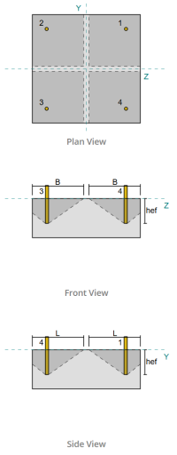
Πριν υπολογίσετε την χωρητικότητα ξεμπλοκάρισμα, πρέπει πρώτα να καθορίσουμε εάν το μέλος χαρακτηρίζεται ως στενό μέλος. Σύμφωνα με CSA A23.3:19 Ρήτρα Δ.6.2.3, το μέλος δεν πληροί τα κριτήρια για στενό μέλος. Επομένως, το δεδομένο αποτελεσματικό μήκος ενσωμάτωσης θα χρησιμοποιηθούν στους υπολογισμούς.
Χρησιμοποιώντας CSA A23.3:19 Εξ. Δ.5, υπολογίζουμε το Μέγιστη επιφάνεια κώνου σκυροδέματος για μια μόνο άγκυρα, με βάση το αποτελεσματικό μήκος ενσωμάτωσης.
\(
ΕΝΑ_{Θυμάμαι} = 9 (ω_{εφ,s1})💕⬛ Αγορά Indocin από 9 \φορές (130 \, \κείμενο{χιλ})💕⬛ Αγορά Indocin από 152100 \, \κείμενο{χιλ}^ 2
\)
Ομοίως, χρησιμοποιούμε το πραγματικό μήκος ενσωμάτωσης για να υπολογίσουμε το Πραγματική προβλεπόμενη περιοχή κώνου σκυροδέματος της μονής άγκυρας.
\(
ΕΝΑ_{Αρ} = L_{Αρ} ΣΙ_{Αρ} = 270 \, \κείμενο{χιλ} \φορές 270 \, \κείμενο{χιλ} = 72900 \, \κείμενο{χιλ}^ 2
\)
Οπου,
\(
ΜΕΓΑΛΟ_{Αρ} = αριστερά( \min left( ντο_{\κείμενο{αριστερά},s1}, 1.5 ω_{εφ,s1} \σωστά) \σωστά) + \αριστερά( \min left( ντο_{\κείμενο{σωστά},s1}, 1.5 ω_{εφ,s1} \σωστά) \σωστά)
\)
\(
ΜΕΓΑΛΟ_{Αρ} = αριστερά( \min left( 475 \, \κείμενο{χιλ}, 1.5 \φορές 130 \, \κείμενο{χιλ} \σωστά) \σωστά) + \αριστερά( \min left( 75 \, \κείμενο{χιλ}, 1.5 \φορές 130 \, \κείμενο{χιλ} \σωστά) \σωστά)
\)
\(
ΜΕΓΑΛΟ_{Αρ} = 270 \, \κείμενο{χιλ}
\)
\(
ΣΙ_{Αρ} = αριστερά( \min left( ντο_{\κείμενο{μπλουζα},s1}, 1.5 ω_{εφ,s1} \σωστά) \σωστά) + \αριστερά( \min left( ντο_{\κείμενο{κάτω μέρος},s1}, 1.5 ω_{εφ,s1} \σωστά) \σωστά)
\)
\(
ΣΙ_{Αρ} = αριστερά( \min left( 75 \, \κείμενο{χιλ}, 1.5 \φορές 130 \, \κείμενο{χιλ} \σωστά) \σωστά) + \αριστερά( \min left( 475 \, \κείμενο{χιλ}, 1.5 \φορές 130 \, \κείμενο{χιλ} \σωστά) \σωστά)
\)
\(
ΣΙ_{Αρ} = 270 \, \κείμενο{χιλ}
\)
Επόμενο, Αξιολογούμε το παράγοντας βασική αντοχή σε διάσπαση σκυροδέματος μιας μόνο άγκυρας που χρησιμοποιεί CSA A23.3:19 Εξ. Δ.6
\(
Ν_{br} = k_c phi lambda_a sqrt{\frac{f'_c}{\κείμενο{MPa}}} \αριστερά( \frac{ω_{εφ,s1}}{\κείμενο{χιλ}} \σωστά)^{1.5} R N
\)
\(
Ν_{br} = 10 \φορές 0.65 \φορές 1 \φορές sqrt{\frac{20.68 \, \κείμενο{MPa}}{1 \, \κείμενο{MPa}}} \φορές αριστερά( \frac{130 \, \κείμενο{χιλ}}{1 \, \κείμενο{χιλ}} \σωστά)^{1.5} \φορές 1 \φορές 0.001 \, \κείμενο{ΚΝ} = 43.813 \, \κείμενο{ΚΝ}
\)
Οπου,
- \(κ_{ντο} = 10\) για άγκυρες
- \(\lambda = 1.0 \) Για σκυρόδεμα κανονικού βάρους
Τώρα, Αξιολογούμε τις επιδράσεις της γεωμετρίας με τον υπολογισμό του συντελεστής ακμής.
Η συντομότερη απόσταση ακμής της ομάδας αγκύρωσης καθορίζεται ως:
\(
ντο_{ένα,\κείμενο{ελάχ}} = min αριστερά( ντο_{\κείμενο{αριστερά},s1}, ντο_{\κείμενο{σωστά},s1}, ντο_{\κείμενο{μπλουζα},s1}, ντο_{\κείμενο{κάτω μέρος},s1} \σωστά) = min αριστερά( 475 \, \κείμενο{χιλ}, 75 \, \κείμενο{χιλ}, 75 \, \κείμενο{χιλ}, 475 \, \κείμενο{χιλ} \σωστά) = 75 \, \κείμενο{χιλ}
\)
Σύμφωνα με CSA A23.3:19 Εξ. Δ.10 και Δ.11, το ξεμπλοκάρισμα συντελεστής ακμής είναι:
\(
\Psi_{εκδ,Ν} = min αριστερά( 1.0, 0.7 + 0.3 \αριστερά( \frac{ντο_{ένα,\κείμενο{ελάχ}}}{1.5 ω_{εφ,s1}} \σωστά) \σωστά) = min αριστερά( 1, 0.7 + 0.3 \φορές αριστερά( \frac{75 \, \κείμενο{χιλ}}{1.5 \φορές 130 \, \κείμενο{χιλ}} \σωστά) \σωστά) = 0.81538
\)
Επιπλέον, και οι δύο συντελεστής πυρόλυσης και το συντελεστής διαίρεσης λαμβάνονται ως:
\(
\Psi_{ντο,Ν} = 1
\)
\(
\Psi_{cp,Ν} = 1
\)
Τότε, Συνδυάζουμε όλους αυτούς τους παράγοντες και τη χρήση ACI 318-19 Εξ. 17.6.2.1σι Για να αξιολογήσετε το παράγοντας αντοχή στη διάσπαση του σκυροδέματος της μονής άγκυρας:
\(
Ν_{cbr} = αριστερά( \frac{ΕΝΑ_{Αρ}}{ΕΝΑ_{Θυμάμαι}} \σωστά) \Psi_{εκδ,Ν} \Psi_{ντο,Ν} \Psi_{cp,Ν} Ν_{br} = αριστερά( \frac{72900 \, \κείμενο{χιλ}^ 2}{152100 \, \κείμενο{χιλ}^ 2} \σωστά) \φορές 0.81538 \φορές 1 \φορές 1 \φορές 43.813 \, \κείμενο{ΚΝ} = 17.122 \, \κείμενο{ΚΝ}
\)
Θυμηθείτε τους προηγουμένως υπολογισμένους φορτίο έντασης ανά άγκυρα:
\(
Ν_{φά} = frac{N_x}{n_{ένα,μικρό}} = frac{50 \, \κείμενο{ΚΝ}}{4} = 12.5 \, \κείμενο{ΚΝ}
\)
Από 12.5 ΚΝ < 17.122 ΚΝ Η χωρητικότητα ξεμπλοκάρισμα του σκυροδέματος είναι επαρκής.
Αυτός ο συγκεκριμένος υπολογισμός διαχωρισμού βασίζεται στο Anchor ID #1. Η ίδια χωρητικότητα θα ισχύει και για τις υπόλοιπες άγκυρες λόγω του συμμετρικού σχεδιασμού.
Ελεγχος #5: Υπολογίστε την χωρητικότητα αγκύρωσης
Η ικανότητα απομάκρυνσης μιας άγκυρας διέπεται από την αντίσταση στο ενσωματωμένο άκρο της. Για αγκυλωτές άγκυρες, εξαρτάται από το μήκος του γάντζου του.
Υπολογίζουμε το βασική αντίσταση έλξης άγκυρας ανά CSA A23.3:19 Εξ. Δ.17.
\(
Ν_{πρ} = Psi_{ντο,Π} 0.9 \phi (f'_c) e_h d_a R = 1 \φορές 0.9 \φορές 0.65 \φορές (20.68 \, \κείμενο{MPa}) \φορές 60 \, \κείμενο{χιλ} \φορές 19.05 \, \κείμενο{χιλ} \φορές 1 = 13.828 \, \κείμενο{ΚΝ}
\)
Θυμηθείτε τους προηγουμένως υπολογισμένους φορτίο έντασης ανά άγκυρα:
\(
Ν_{φά} = frac{N_x}{n_{ένα,τ}} = frac{50 \, \κείμενο{ΚΝ}}{4} = 12.5 \, \κείμενο{ΚΝ}
\)
Από 12.5 ΚΝ < 13.828 ΚΝ, η χωρητικότητα αγκύρωσης είναι επαρκής.
Ελεγχος #6: Υπολογίστε την χωρητικότητα εκτόξευσης πλευρικού προσώπου σε κατεύθυνση y
Αυτός ο υπολογισμός δεν ισχύει για αγκυλωτές άγκυρες.
Ελεγχος #7: Υπολογίστε την χωρητικότητα εκτόξευσης πλευρικού προσώπου στην κατεύθυνση z
Αυτός ο υπολογισμός δεν ισχύει για αγκυλωτές άγκυρες.
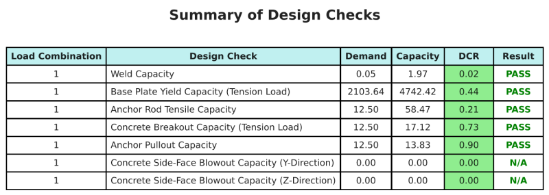
Περίληψη σχεδίου
ο Λογισμικό σχεδιασμού πλάκας βάσης SkyCIV Μπορεί να δημιουργήσει αυτόματα μια αναφορά υπολογισμού βήμα προς βήμα για αυτό το παράδειγμα σχεδιασμού. Παρέχει επίσης μια περίληψη των επιταγών που εκτελούνται και των προκύπτουσων αναλογιών τους, καθιστώντας τις πληροφορίες κατανοητές με μια ματιά. Παρακάτω είναι ένας πίνακας συνοπτικών δείγματος, που περιλαμβάνεται στην αναφορά.
Αναφορά δείγματος SkyCIV
Δείτε το επίπεδο λεπτομέρειας και σαφήνειας που μπορείτε να περιμένετε από μια αναφορά σχεδίασης πλάκας βάσης SkyCiv. Η αναφορά περιλαμβάνει όλους τους βασικούς ελέγχους σχεδιασμού, εξισώσεις, και τα αποτελέσματα παρουσιάζονται σε σαφή και ευανάγνωστη μορφή. Είναι πλήρως συμβατό με τα πρότυπα σχεδιασμού. Κάντε κλικ παρακάτω για να προβάλετε ένα δείγμα αναφοράς που δημιουργήθηκε με χρήση του SkyCiv Base Plate Calculator.
Αγορά λογισμικού πλάκας βάσης
Αγοράστε μόνη σας την πλήρη έκδοση της μονάδας σχεδίασης πλάκας βάσης χωρίς άλλες μονάδες SkyCiv. Αυτό σας δίνει ένα πλήρες σύνολο αποτελεσμάτων για σχεδιασμό πλάκας βάσης, συμπεριλαμβανομένων λεπτομερών αναφορών και περισσότερων λειτουργιών.