Παράδειγμα σχεδιασμού πλάκας βάσης χρησιμοποιώντας AISC 360-22 και ACI 318-19
Προβληματική δήλωση
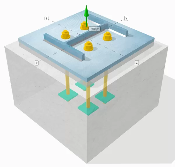
Προσδιορίστε εάν η σχεδιασμένη σύνδεση πλάκας στη στήλη σε βάση είναι επαρκής για φορτίο τάσης 20 kip.
Δεδομένα
Στήλη:
Ενότητα στήλης: W12x53
Επιφάνεια στήλης: 15.6 σε2
Υλικό στήλης: A992
Πλάκα βάσης:
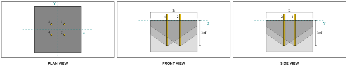
Διαστάσεις πλάκας βάσης: 18 σε x 18 σε
Πάχος πλάκας βάσης: 3/4 σε
Υλικό πλάκας βάσης: A36
Πηκτώ:
Πάχος ενέματα: 1 σε
Σκυρόδεμα:
Διαστάσεις σκυροδέματος: 22 σε x 22 σε
Πάχος σκυροδέματος: 15 σε
Σκυρόδεμα: 4000 psi
Ραγισμένα ή αδιευκρίνιστα: Ραγισμένος
Άγκυρες:
Διάμετρος άγκυρας: 3/4 σε
Αποτελεσματικό μήκος ενσωμάτωσης: 12 σε
Ενσωματωμένο πλάτος πλάκας: 3 σε
Ενσωματωμένο πάχος πλάκας: 1/4 σε
Απόσταση αντιστάθμισης άγκυρας από την όψη του ιστού της στήλης: 2.8275 σε
Συγκολλήσεις:
Μέγεθος συγκόλλησης: 1/4 σε
Η ταξινόμηση μετάλλων πλήρωσης: Ε70ΧΧ
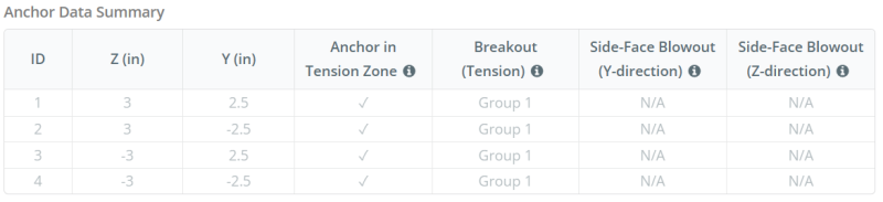
Δεδομένα αγκυροβόλησης (από Υπολογιστής Skyciv):
Μοντέλο στο δωρεάν εργαλείο SkyCiv
Μοντελοποιήστε το παραπάνω σχέδιο πλάκας βάσης χρησιμοποιώντας το δωρεάν διαδικτυακό μας εργαλείο σήμερα! Δεν απαιτείται εγγραφή.
Ορισμοί
Διαδρομή φόρτωσης:
Όταν μια πλάκα βάσης υποβάλλεται σε ανύψωση (εντάσεως) δυνάμεις, Αυτές οι δυνάμεις μεταφέρονται στις ράβδους άγκυρας, που με τη σειρά τους προκαλούν στιγμές κάμψης στην πλάκα βάσης. Η δράση κάμψης μπορεί να απεικονιστεί ως κάμψη που συμβαίνουν γύρω από τις φλάντζες ή τον ιστό της ενότητας στήλης, ανάλογα με το πού τοποθετούνται οι άγκυρες.
Στο Λογισμικό σχεδιασμού πλάκας βάσης SkyCIV, μόνο άγκυρες που βρίσκονται μέσα στο ζώνη τάσης άγκυρας θεωρούνται αποτελεσματικοί στην αντιστάθμιση της ανύψωσης. Αυτή η ζώνη περιλαμβάνει συνήθως περιοχές κοντά στις φλάντζες της στήλης ή στο διαδίκτυο. Οι άγκυρες εκτός αυτής της ζώνης δεν συμβάλλουν στην αντίσταση στην ένταση και αποκλείονται από τους υπολογισμούς ανύψωσης.
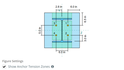
Για να προσδιορίσετε την αποτελεσματική περιοχή της πλάκας βάσης που αντιστέκεται στην κάμψη, ένα 45-διασπορά υποτίθεται από την κεντρική γραμμή κάθε ράβδου αγκύρωσης προς την επιφάνεια της στήλης. Αυτή η διασπορά ορίζει το αποτελεσματικό μήκος συγκόλλησης και βοηθά στη δημιουργία του αποτελεσματικό πλάτος κάμψης του πιάτου.
Η υπόθεση απλοποιεί την ανάλυση της πλάκας βάσης προσεγγίζοντας τον τρόπο με τον οποίο εξαπλώνεται η δύναμη ανύψωσης μέσω της πλάκας.
Ομάδες άγκυρας:
ο Λογισμικό σχεδιασμού πλάκας βάσης SkyCIV Περιλαμβάνει ένα διαισθητικό χαρακτηριστικό που προσδιορίζει ποιες άγκυρες αποτελούν μέρος μιας ομάδας αγκύρωσης για αξιολόγηση ξέσπασμα σκυροδέματος και σκυρόδεμαe-face blowout αποτυχία.
Ενα ομάδα άγκυρας Αποτελείται από πολλαπλές άγκυρες με παρόμοια αποτελεσματικά βάθη ενσωμάτωσης και απόσταση, και είναι αρκετά κοντά ώστε τους Οι προβλεπόμενες περιοχές αντίστασης επικαλύπτονται. Όταν ομαδοποιούνται άγκυρες, Οι ικανότητές τους συνδυάζονται για να αντισταθούν στη συνολική δύναμη έντασης που εφαρμόζεται στην ομάδα.
Οι άγκυρες που δεν πληρούν τα κριτήρια ομαδοποίησης αντιμετωπίζονται ως άγκυρες. Σε αυτήν την περίπτωση, Μόνο η δύναμη τάσης στην ατομική άγκυρα ελέγχεται από τη δική της αποτελεσματική περιοχή αντίστασης.
Υπολογισμοί βήμα προς βήμα
Ελεγχος #1: Υπολογίστε τη χωρητικότητα συγκόλλησης
Να ξεκινήσω, Πρέπει να υπολογίσουμε το φορτίο ανά άγκυρα και το αποτελεσματικό μήκος συγκόλλησης ανά άγκυρα. Το αποτελεσματικό μήκος συγκόλλησης καθορίζεται από το συντομότερο μήκος από το 45° διασπορά, περιορίζεται από το πραγματικό μήκος συγκόλλησης και απόσταση άγκυρας.
Για αυτόν τον υπολογισμό, Οι άγκυρες ταξινομούνται και άκρο άγκυρας ή ενδιάμεσες άγκυρες. Οι τελικές άγκυρες βρίσκονται στα άκρα μιας σειράς ή στήλης άγκυρας, ενώ οι ενδιάμεσες άγκυρες τοποθετούνται μεταξύ τους. Η μέθοδος υπολογισμού διαφέρει για καθένα και εξαρτάται από τη γεωμετρία της στήλης. Σε αυτό το παράδειγμα, Υπάρχουν δύο άγκυρες κατά μήκος του ιστού, Και οι δύο ταξινομούνται ως τελικές άγκυρες.
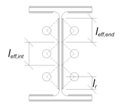
Για τελικές άγκυρες, Το αποτελεσματικό μήκος συγκόλλησης περιορίζεται από την διαθέσιμη απόσταση από την κεντρική γραμμή αγκύρωσης στο φιλέτο της στήλης. Η διασπορά 45 ° δεν πρέπει να εκτείνεται πέρα από αυτό το όριο.
\(
l_r = frac{ρε_{διάσελο} – 2T_F – 2r_{διάσελο} – μικρό_(n_{ένα,πλευρά} – 1)}{2} = frac{12.1 \, \κείμενο{σε} – 2 \φορές 0.575 \, \κείμενο{σε} – 2 \φορές 0.605 \, \κείμενο{σε} – 5 \, \κείμενο{σε} \φορές (2 – 1)}{2} = 2.37 \, \κείμενο{σε}
\)
Στην εσωτερική πλευρά, Το πραγματικό μήκος περιορίζεται κατά το ήμισυ της απόστασης αγκύρωσης. Το συνολικό αποτελεσματικό μήκος συγκόλλησης για την άγκυρα τελικού είναι το άθροισμα των εξωτερικών και εσωτερικών μήκους.
\(
μεγάλο_{εφ,τέλος} = min(κάνω, 0.5μικρό_) + \ελάχ(κάνω, L_R)
\)
\(
μεγάλο_{εφ,τέλος} = min(2.8275 \, \κείμενο{σε}, 0.5 \φορές 5 \, \κείμενο{σε}) + \ελάχ(2.8275 \, \κείμενο{σε}, 2.37 \, \κείμενο{σε}) = 4.87 \, \κείμενο{σε}
\)
Για αυτό το παράδειγμα, ο τελικό αποτελεσματικό μήκος συγκόλλησης για το Web Anchor θεωρείται ως το πραγματικό μήκος της άγκυρας τελικής.
\(
μεγάλο_{εφ} = l_{εφ,τέλος} = 4.87 \, \κείμενο{σε}
\)
Επόμενο, ας υπολογίσουμε το φορτίο ανά άγκυρα. Για ένα δεδομένο σύνολο τεσσάρων (4) άγκυρες, Το φορτίο ανά άγκυρα είναι:
\(
T_{εσύ,άγκυρα} = frac{N_x}{n_{ένα,τ}} = frac{20 \, \κείμενο{δέρμα μόσχου ακατέργαστου}}{4} = 5 \, \κείμενο{δέρμα μόσχου ακατέργαστου}
\)
Χρήση του υπολογισμένου αποτελεσματικού μήκους συγκόλλησης, Μπορούμε τώρα να καθορίσουμε το απαιτούμενη δύναμη ανά μονάδα μήκους στη συγκόλληση.
\(
r_u = frac{T_{εσύ,άγκυρα}}{μεγάλο_{εφ}} = frac{5 \, \κείμενο{δέρμα μόσχου ακατέργαστου}}{4.87 \, \κείμενο{σε}} = 1.0267 \, \κείμενο{kip/in}
\)
Τώρα, θα το χρησιμοποιησουμε AISC 360-22, Κεφάλαιο J2.4 Για να υπολογίσετε τη δύναμη σχεδιασμού της συγκόλλησης φιλέτου.
Δεδομένου ότι το εφαρμοσμένο φορτίο είναι καθαρά αξονική ένταση, η γωνία \(\θήτα) λαμβάνεται ως 90 °, και ο συντελεστής κατεύθυνσης αντοχής KDS υπολογίζεται σύμφωνα με AISC 360-22 Εξ. J2-5.
\(
κ_{δδ} = 1.0 + 0.5(\χωρίς(\θήτα))^{1.5} = 1 + 0.5 \φορές (\χωρίς(1.5708))^{1.5} = 1.5
\)
Τελικά, θα εφαρμόσουμε AISC 360-22 Εξ. J2-4 Για να προσδιορίσετε το Σχεδιασμός αντοχή της συγκόλλησης φιλέτου ανά μονάδα μήκους.
\(
\phi r_n = phi 0.6 ΦΑ_{Exx} ΜΙ_{β,ιστός} κ_{δδ} = 0.75 \φορές 0.6 \φορές 70 \, \κείμενο{ksi} \φορές 0.177 \, \κείμενο{σε} \φορές 1.5 = 8.3633 \, \κείμενο{kip/in}
\)
Από 1.0267 KPI < 8.3633 KPI, Η χωρητικότητα συγκόλλησης είναι επαρκής.
Ελεγχος #2: Υπολογίστε τη χωρητικότητα κάμψης πλάκας βάσης λόγω φορτίου τάσης
Χρήση ΤΦορτώνεται ανά άγκυρα και το OΑπόσταση από το κέντρο της άγκυρας στο πρόσωπο της στήλης (που χρησιμεύει ως εκκεντρότητα φορτίου), Η στιγμή που εφαρμόζεται στην πλάκα βάσης μπορεί να υπολογιστεί χρησιμοποιώντας ένα υποστήριγμα υπόθεση.
\(
M_u = t_{εσύ,\κείμενο{άγκυρα}} ε = 5 \, \κείμενο{δέρμα μόσχου ακατέργαστου} \φορές 2.8275 \, \κείμενο{σε} = 14.137 \, \κείμενο{δέρμα μόσχου ακατέργαστου} \cdot text{σε}
\)
Επόμενο, Χρησιμοποιώντας τον υπολογισμόD Αποτελεσματικό μήκος συγκόλλησηςο προηγούμενος έλεγχος ως πλάτος κάμψης, Μπορούμε να υπολογίσουμε το Υπολογίζει τη φέρουσα ικανότητα της πλάκας βάσης χρησιμοποιώντας AISC 360-22, Εξίσωση 2-1:
\(
\phi M_n = phi F_{και,\κείμενο{bp}} Z_{\κείμενο{εφ}} = 0.9 \φορές 36 \, \κείμενο{ksi} \φορές 0.68484 \, \κείμενο{σε}^3 = 22.189 \, \κείμενο{δέρμα μόσχου ακατέργαστου} \cdot text{σε}
\)
Οπου,
\(
Z_{\κείμενο{εφ}} = frac{μεγάλο_{\κείμενο{εφ}} (αυτό είναι ένα πολύ σημαντικό στάδιο στο σχεδιασμό ενός τοίχου αντιστήριξης, καθώς η μη αντιστοίχιση των σωστών αναλογικών διαστάσεων από την αρχή σε κάθε στοιχείο μπορεί να οδηγήσει στην ανάγκη πολλών επαναλήψεων για να συμμορφωθεί ο τοίχος αντιστήριξης με τις απαιτήσεις ευστάθειας ή υπερμεγέθη σύστημα που πληροί όλες τις απαιτήσεις, αλλά χρησιμοποιεί πολύ περισσότερο υλικό από το θεωρητικό ελάχιστο{\κείμενο{bp}})^ 2}{4} = frac{4.87 \, \κείμενο{σε} \φορές (0.75 \, \κείμενο{σε})^ 2}{4} = 0.68484 \, \κείμενο{σε}^ 3
\)
Από 14.137 κοτόπουλο < 22.189 κοτόπουλο, Η ικανότητα απόδοσης της κάμψης της πλάκας βάσης είναι επαρκής.
Ελεγχος #3: Υπολογίστε την ικανότητα εφελκυσμού της ράβδου άγκυρας
Για να αξιολογηθεί η ικανότητα εφελκυσμού της ράβδου αγκύρωσης, θα το χρησιμοποιησουμε ACI 318-19 Εξίσωση 17.6.1.2.
Πρώτα, καθορίζουμε το συγκεκριμένη αντοχή εφελκυσμού του χάλυβα άγκυρας. Αυτή είναι η χαμηλότερη τιμή που επιτρέπεται από ACI 318-19 Ρήτρα 17.6.1.2, Αναφορικά με τις ιδιότητες του υλικού στο AISC 360-22 Πίνακας J3.2.
\(
φά_{\κείμενο{Γιούτα}} = min αριστερά( 0.75 ΦΑ_{εσύ,\κείμενο{Α.Κ.}}, 1.9 ΦΑ_{και,\κείμενο{Α.Κ.}}, 125 \σωστά) = min αριστερά( 0.75 \φορές 120 \, \κείμενο{ksi}, 1.9 \φορές 92 \, \κείμενο{ksi}, 125.00 \, \κείμενο{ksi} \σωστά) = 90 \, \κείμενο{ksi}
\)
Επόμενο, υπολογίζουμε το αποτελεσματική περιοχή διατομής της ράβδου άγκυρας. Αυτό βασίζεται ACI 318-19 Ρήτρα σχολίων R17.6.1.2, που αντιπροσωπεύει τη γεωμετρία του νήματος. Ο αριθμός των νημάτων ανά ίντσα λαμβάνεται από ASME B1.1-2019 Πίνακας 1.
\(
ΕΝΑ_{Ξέρω,Ν} = frac{\πι}{4} \αριστερά( d_a – \frac{0.9743}{n_t} \σωστά)^2 = frac{\πι}{4} \φορές αριστερά( 0.75 \, \κείμενο{σε} – \frac{0.9743}{10 \, \κείμενο{σε}^{-1}} \σωστά)💕⬛ Αγορά Indocin από 0.33446 \, \κείμενο{σε}^ 2
\)
Με αυτές τις τιμές, Εφαρμόζουμε ACI 318-19 Εξίσωση 17.6.1.2 Για να υπολογίσετε το Σχεδιασμός αντοχή εφελκυσμού της ράβδου άγκυρας.
\(
\phi Ν_{προς την} = phi Α_{Ξέρω,Ν} φά_{\κείμενο{Γιούτα}} = 0.75 \φορές 0.33446 \, \κείμενο{σε}^2 φορές 90 \, \κείμενο{ksi} = 22.576 \, \κείμενο{δέρμα μόσχου ακατέργαστου}
\)
Θυμηθείτε τους προηγουμένως υπολογισμένους φορτίο έντασης ανά άγκυρα:
\(
Ν_{κάνω} = frac{N_x}{n_{ένα,τ}} = frac{20 \, \κείμενο{δέρμα μόσχου ακατέργαστου}}{4} = 5 \, \κείμενο{δέρμα μόσχου ακατέργαστου}
\)
Από 5 δέρμα μόσχου ακατέργαστου < 22.576 δέρμα μόσχου ακατέργαστου, Η χωρητικότητα εφελκυσμού της ράβδου άγκυρας είναι επαρκής.
Ελεγχος #4: Υπολογίστε τη χωρητικότητα ξεμπλοκάρισμα από σκυρόδεμα σε ένταση
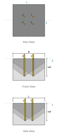
Πριν υπολογίσετε την χωρητικότητα ξεμπλοκάρισμα, πρέπει πρώτα να καθορίσουμε εάν το μέλος χαρακτηρίζεται ως στενό μέλος. Σύμφωνα με ACI 318-19 Ρήτρα 17.6.2.1.2, Το μέλος πληροί τα κριτήρια για ένα στενό μέλος. Επομένως, Πρέπει να χρησιμοποιείται ένα τροποποιημένο αποτελεσματικό μήκος ενσωμάτωσης στους υπολογισμούς.
Είναι αποφασισμένο ότι το Τροποποιημένο αποτελεσματικό μήκος ενσωμάτωσης, h'ef, της ομάδας αγκύρωσης είναι:
\(
h'_{\κείμενο{εφ}} = 5.667 \, \κείμενο{σε}
\)
Χρησιμοποιώντας ACI 318-19 Ρήτρα 17.6.2, υπολογίζουμε το Μέγιστη επιφάνεια κώνου σκυροδέματος για μια μόνο άγκυρα, με βάση το τροποποιημένο αποτελεσματικό μήκος ενσωμάτωσης.
\(
ΕΝΑ_{Ν_{συν}} = 9 \αριστερά( h'_{εφ,G1} \σωστά)💕⬛ Αγορά Indocin από 9 \φορές αριστερά( 5.6667 \, \κείμενο{σε} \σωστά)💕⬛ Αγορά Indocin από 289 \, \κείμενο{σε}^ 2
\)
Ομοίως, Χρησιμοποιούμε το τροποποιημένο αποτελεσματικό μήκος ενσωμάτωσης για να υπολογίσουμε το Πραγματική προβλεπόμενη περιοχή κώνου σκυροδέματος της ομάδας αγκύρωσης.
\(
ΕΝΑ_{N_c} = min αριστερά( n_{ένα,G1} ΕΝΑ_{Ν_{συν}}, ΜΕΓΑΛΟ_{N_c} ΣΙ_{N_c} \σωστά) = min αριστερά( 4 \φορές 289 \, \κείμενο{σε}^ 2, 22 \, \κείμενο{σε} \φορές 22 \, \κείμενο{σε} \σωστά) = 484 \, \κείμενο{σε}^ 2
\)
Οπου,
\(
ΜΕΓΑΛΟ_{N_c} = min αριστερά( ντο_{\κείμενο{αριστερά},G1}, 1.5 h'_{\κείμενο{εφ},G1} \σωστά)
+ \αριστερά( \min left( μικρό_{\κείμενο{άθροισμα},με,G1}, 3 h'_{\κείμενο{εφ},G1} \αριστερά( n_{με,G1} – 1 \σωστά) \σωστά) \σωστά)
+ \min left( ντο_{\κείμενο{σωστά},G1}, 1.5 h'_{\κείμενο{εφ},G1} \σωστά)
\)
\(
ΜΕΓΑΛΟ_{N_c} = min αριστερά( 8 \, \κείμενο{σε}, 1.5 \φορές 5.6667 \, \κείμενο{σε} \σωστά)
+ \αριστερά( \min left( 6 \, \κείμενο{σε}, 3 \φορές 5.6667 \, \κείμενο{σε} \φορές αριστερά( 2 – 1 \σωστά) \σωστά) \σωστά)
+ \min left( 8 \, \κείμενο{σε}, 1.5 \φορές 5.6667 \, \κείμενο{σε} \σωστά)
\)
\(
ΜΕΓΑΛΟ_{N_c} = 22 \, \κείμενο{σε}
\)
\(
ΣΙ_{N_c} = min αριστερά( ντο_{\κείμενο{μπλουζα},G1}, 1.5 h'_{\κείμενο{εφ},G1} \σωστά)
+ \αριστερά( \min left( μικρό_{\κείμενο{άθροισμα},και,G1}, 3 h'_{\κείμενο{εφ},G1} \αριστερά( n_{και,G1} – 1 \σωστά) \σωστά) \σωστά)
+ \min left( ντο_{\κείμενο{κάτω μέρος},G1}, 1.5 h'_{\κείμενο{εφ},G1} \σωστά)
\)
\(
ΣΙ_{N_c} = min αριστερά( 8.5 \, \κείμενο{σε}, 1.5 \φορές 5.6667 \, \κείμενο{σε} \σωστά)
+ \αριστερά( \min left( 5 \, \κείμενο{σε}, 3 \φορές 5.6667 \, \κείμενο{σε} \φορές αριστερά( 2 – 1 \σωστά) \σωστά) \σωστά)
+ \min left( 8.5 \, \κείμενο{σε}, 1.5 \φορές 5.6667 \, \κείμενο{σε} \σωστά)
\)
\(
ΣΙ_{N_c} = 22 \, \κείμενο{σε}
\)
Επόμενο, Αξιολογούμε το βασική δύναμη ξεμπλοκάρισμα από σκυρόδεμα μιας μόνο άγκυρας που χρησιμοποιεί ACI 318-19 Ρήτρα 17.6.2.2.1
\(
N_b = k_c lambda_a sqrt{\frac{f'_c}{\κείμενο{psi}}} \αριστερά( \frac{h'_{\κείμενο{εφ},G1}}{\κείμενο{σε}} \σωστά)^{1.5} \, \κείμενο{lbf}
\)
\(
Ν_β = 24 \φορές 1 \φορές sqrt{\frac{4 \, \κείμενο{ksi}}{0.001 \, \κείμενο{ksi}}} \φορές αριστερά( \frac{5.6667 \, \κείμενο{σε}}{1 \, \κείμενο{σε}} \σωστά)^{1.5} \φορές 0.001 \, \κείμενο{δέρμα μόσχου ακατέργαστου} = 20.475 \, \κείμενο{δέρμα μόσχου ακατέργαστου}
\)
Οπου,
- \(κ_{ντο} = 24\) για άγκυρες
- \(\lambda = 1.0 \) Για σκυρόδεμα κανονικού βάρους
Τώρα, Αξιολογούμε τις επιδράσεις της γεωμετρίας με τον υπολογισμό του συντελεστής ακμής και το παράγοντας εκκεντρότητας.
Η συντομότερη απόσταση ακμής της ομάδας αγκύρωσης καθορίζεται ως:
\(
ντο_{ένα,\κείμενο{ελάχ}} = min αριστερά( ντο_{\κείμενο{αριστερά},G1}, ντο_{\κείμενο{σωστά},G1}, ντο_{\κείμενο{μπλουζα},G1}, ντο_{\κείμενο{κάτω μέρος},G1} \σωστά)
= min αριστερά( 8 \, \κείμενο{σε}, 8 \, \κείμενο{σε}, 8.5 \, \κείμενο{σε}, 8.5 \, \κείμενο{σε} \σωστά) = 8 \, \κείμενο{σε}
\)
Σύμφωνα με ACI 318-19 Ρήτρα 17.6.2.4.1, το ξεμπλοκάρισμα συντελεστής ακμής είναι:
\(
\Psi_{εκδ,Ν} = min αριστερά( 1.0, 0.7 + 0.3 \αριστερά( \frac{ντο_{ένα,\κείμενο{ελάχ}}}{1.5 h'_{\κείμενο{εφ},G1}} \σωστά) \σωστά)
= min αριστερά( 1, 0.7 + 0.3 \φορές αριστερά( \frac{8 \, \κείμενο{σε}}{1.5 \φορές 5.6667 \, \κείμενο{σε}} \σωστά) \σωστά) = 0.98235
\)
Δεδομένου ότι το φορτίο τάσης εφαρμόζεται στο κέντρο της ομάδας αγκύρωσης, Η εκκεντρότητα είναι μηδενική. Ετσι, ο παράγοντας εκκεντρότητας, Επίσης από τη ρήτρα 17.6.2.4.1, είναι:
\(
\Psi_{εκ,Ν} = min αριστερά( 1.0, \frac{1}{1 + \frac{2 και'_N}{3 h'_{\κείμενο{εφ},G1}}} \σωστά)
= min αριστερά( 1, \frac{1}{1 + \frac{2 \φορές 0}{3 \φορές 5.6667 \, \κείμενο{σε}}} \σωστά) = 1
\)
Επιπλέον, και οι δύο συντελεστής πυρόλυσης και το συντελεστής διαίρεσης λαμβάνονται ως:
\(
\Psi_{ντο,Ν} = 1
\)
\(
\Psi_{cp,Ν} = 1
\)
Τότε, Συνδυάζουμε όλους αυτούς τους παράγοντες και τη χρήση ACI 318-19 Εξ. 17.6.2.1σι Για να αξιολογήσετε το Δύναμη σκυροδέματος της ομάδας αγκύρωσης:
\(
\phi Ν_{cbg} = phi αριστερά( \frac{ΕΝΑ_{N_c}}{ΕΝΑ_{Ν_{συν}}} \σωστά) \Psi_{εκ,Ν} \Psi_{εκδ,Ν} \Psi_{ντο,Ν} \Psi_{cp,Ν} Ν_β
\)
\(
\phi Ν_{cbg} = 0.7 \φορές αριστερά( \frac{484 \, \κείμενο{σε}^ 2}{289 \, \κείμενο{σε}^ 2} \σωστά) \φορές 1 \φορές 0.98235 \φορές 1 \φορές 1 \φορές 20.475 \, \κείμενο{δέρμα μόσχου ακατέργαστου} = 23.58 \, \κείμενο{δέρμα μόσχου ακατέργαστου}
\)
ο Συνολικό φορτίο εφαρμοζόμενης τάσης Στην ομάδα αγκύρωσης είναι το προϊόν του μεμονωμένου φορτίου αγκύρωσης και ο αριθμός των άγκυρων:
\(
Ν_{κάνω} = αριστερά( \frac{N_x}{n_{ένα,τ}} \σωστά) n_{ένα,G1} = αριστερά( \frac{20 \, \κείμενο{δέρμα μόσχου ακατέργαστου}}{4} \σωστά) \φορές 4 = 20 \, \κείμενο{δέρμα μόσχου ακατέργαστου}
\)
Από 20 kips < 23.58 kips , Η χωρητικότητα ξεμπλοκάρισμα του σκυροδέματος είναι επαρκής.
Ελεγχος #5: Υπολογίστε την χωρητικότητα αγκύρωσης
Η ικανότητα απομάκρυνσης μιας άγκυρας διέπεται από την αντίσταση στο ενσωματωμένο άκρο της. Να ξεκινήσω, Υπολογίζουμε την περιοχή ρουλεμάν της ενσωματωμένης πλάκας, που είναι η καθαρή περιοχή μετά την αφαίρεση της περιοχής που καταλαμβάνεται από τη ράβδο αγκύρωσης.
Για μια ορθογώνια ενσωματωμένη πλάκα, ο επιφάνεια έδρας υπολογίζεται ως:
\(
ΕΝΑ_{brg} = αριστερά( \αριστερά( αυτό είναι ένα πολύ σημαντικό στάδιο στο σχεδιασμό ενός τοίχου αντιστήριξης, καθώς η μη αντιστοίχιση των σωστών αναλογικών διαστάσεων από την αρχή σε κάθε στοιχείο μπορεί να οδηγήσει στην ανάγκη πολλών επαναλήψεων για να συμμορφωθεί ο τοίχος αντιστήριξης με τις απαιτήσεις ευστάθειας ή υπερμεγέθη σύστημα που πληροί όλες τις απαιτήσεις, αλλά χρησιμοποιεί πολύ περισσότερο υλικό από το θεωρητικό ελάχιστο{ενσωματωμένος _plate} \σωστά)^2 right) – ΕΝΑ_{ράβδος} = αριστερά( \αριστερά( 3 \, \κείμενο{σε} \σωστά)^2 right) – 0.44179 \, \κείμενο{σε}💕⬛ Αγορά Indocin από 8.5582 \, \κείμενο{σε}^ 2
\)
Οπου,
\(
ΕΝΑ_{ράβδος} = frac{\πι}{4} \αριστερά( d_a right)^2 = frac{\πι}{4} \φορές αριστερά( 0.75 \, \κείμενο{σε} \σωστά)💕⬛ Αγορά Indocin από 0.44179 \, \κείμενο{σε}^ 2
\)
Επόμενο, καθορίζουμε το Βασική δύναμη κατάργησης αγκύρωσης χρησιμοποιώντας ACI 318-19 Εξίσωση 17.6.3.2.2a.
\(
Ν_β = 8 ΕΝΑ_{brg} \αριστερά( f'_c σωστά) = 8 \φορές 8.5582 \, \κείμενο{σε}^2 φορές Αριστερά( 4 \, \κείμενο{ksi} \σωστά) = 273.86 \, \κείμενο{δέρμα μόσχου ακατέργαστου}
\)
Στη συνέχεια εφαρμόζουμε τον κατάλληλο συντελεστή αντίστασης και συντελεστής πυρόλυσης:
- Για ραγισμένος σκυρόδεμα, \(\Psi_{cp} = 1.0\)
- Για αδιόρθωτος σκυρόδεμα, \(\Psi_{cp} = 1.4\)
Χρησιμοποιώντας αυτά, Υπολογίζουμε το Σχεδιασμός αντοχής αγκύρωσης άγκυρας σε ένταση ανά ACI 318-19 Εξίσωση 17.6.3.1.
\(
\phi Ν_{π} = Phi psi_{ντο,Π} Ν_β = 0.7 \φορές 1 \φορές 273.86 \, \κείμενο{δέρμα μόσχου ακατέργαστου} = 191.7 \, \κείμενο{δέρμα μόσχου ακατέργαστου}
\)
Θυμηθείτε τους προηγουμένως υπολογισμένους φορτίο έντασης ανά άγκυρα:
\(
Ν_{κάνω} = frac{N_x}{n_{ένα,τ}} = frac{20 \, \κείμενο{δέρμα μόσχου ακατέργαστου}}{4} = 5 \, \κείμενο{δέρμα μόσχου ακατέργαστου}
\)
Από 5 kips < 191.7 kips , η χωρητικότητα αγκύρωσης είναι επαρκής.
Ελεγχος #6: Υπολογίστε την ικανότητα κάμψης της πλάκας
Πρόκειται για συμπληρωματικό έλεγχο που εκτελείται χρησιμοποιώντας το Λογισμικό σχεδιασμού πλάκας βάσης SkyCIV Για να επαληθεύσετε ότι η ενσωματωμένη πλάκα έχει επαρκή ικανότητα κάμψης και δεν θα αποδώσει κάτω από τα εφαρμοσμένα φορτία έλξης.
Πρώτα, καθορίζουμε το μήκος του ελεύθερου (ανυποστήρικτος) τέλος της ενσωματωμένης πλάκας, Μετρείται από την άκρη της στήριξης στο πρόσωπο της ράβδου.
\(
σι’ = frac{αυτό είναι ένα πολύ σημαντικό στάδιο στο σχεδιασμό ενός τοίχου αντιστήριξης, καθώς η μη αντιστοίχιση των σωστών αναλογικών διαστάσεων από την αρχή σε κάθε στοιχείο μπορεί να οδηγήσει στην ανάγκη πολλών επαναλήψεων για να συμμορφωθεί ο τοίχος αντιστήριξης με τις απαιτήσεις ευστάθειας ή υπερμεγέθη σύστημα που πληροί όλες τις απαιτήσεις, αλλά χρησιμοποιεί πολύ περισσότερο υλικό από το θεωρητικό ελάχιστο{ενσωματωμένος _plate} – d_a}{2} = frac{3 \, \κείμενο{σε} – 0.75 \, \κείμενο{σε}}{2} = 1.125 \, \κείμενο{σε}
\)
Επόμενο, υπολογίζουμε το στιγμή κάμψης που προκαλείται από την ομοιόμορφη πίεση εδράνου. Αυτή η πίεση αντιπροσωπεύει τη δύναμη που μεταφέρεται από τη δράση αγκύρωσης στην ενσωματωμένη πλάκα.
\(
m_f = frac{\αριστερά( \frac{T_A}{ΕΝΑ_{brg}} \σωστά) \αριστερά( σι’ \σωστά)^ 2}{2} = frac{\αριστερά( \frac{5 \, \κείμενο{δέρμα μόσχου ακατέργαστου}}{8.5582 \, \κείμενο{σε}^ 2} \σωστά) \φορές αριστερά( 1.125 \, \κείμενο{σε} \σωστά)^ 2}{2} = 0.36971 \, \κείμενο{δέρμα μόσχου ακατέργαστου}
\)
Τελικά, Χρησιμοποιώντας την υπολογιζόμενη ροπή και τις ιδιότητες υλικού, θα καθορίσουμε το ελάχιστο απαιτούμενο πάχος πλάκας να αντισταθείς κάμψη.
\(
αυτό είναι ένα πολύ σημαντικό στάδιο στο σχεδιασμό ενός τοίχου αντιστήριξης, καθώς η μη αντιστοίχιση των σωστών αναλογικών διαστάσεων από την αρχή σε κάθε στοιχείο μπορεί να οδηγήσει στην ανάγκη πολλών επαναλήψεων για να συμμορφωθεί ο τοίχος αντιστήριξης με τις απαιτήσεις ευστάθειας ή υπερμεγέθη σύστημα που πληροί όλες τις απαιτήσεις, αλλά χρησιμοποιεί πολύ περισσότερο υλικό από το θεωρητικό ελάχιστο{ελάχ} = sqrt{\frac{4 M_F}{\Phi f_{y _ep}}} = sqrt{\frac{4 \φορές 0.36971 \, \κείμενο{δέρμα μόσχου ακατέργαστου}}{0.9 \φορές 36 \, \κείμενο{ksi}}} = 0.21364 \, \κείμενο{σε}
\)
Θυμηθείτε το πραγματικό πάχος ενσωματωμένης πλάκας:
\(
αυτό είναι ένα πολύ σημαντικό στάδιο στο σχεδιασμό ενός τοίχου αντιστήριξης, καθώς η μη αντιστοίχιση των σωστών αναλογικών διαστάσεων από την αρχή σε κάθε στοιχείο μπορεί να οδηγήσει στην ανάγκη πολλών επαναλήψεων για να συμμορφωθεί ο τοίχος αντιστήριξης με τις απαιτήσεις ευστάθειας ή υπερμεγέθη σύστημα που πληροί όλες τις απαιτήσεις, αλλά χρησιμοποιεί πολύ περισσότερο υλικό από το θεωρητικό ελάχιστο{πραγματικός} = T_{ενσωματωμένος _plate} = 0.25 \, \κείμενο{σε}
\)
Από 0.21364 σε < 0.25 σε, η ενσωματωμένη ικανότητα κάμψης πλάκας είναι επαρκής.
Ελεγχος #7: Υπολογίστε την χωρητικότητα εκτόξευσης πλευρικού προσώπου σε κατεύθυνση y
Αυτός ο υπολογισμός δεν ισχύει για αυτό το παράδειγμα, ως οι συνθήκες που καθορίζονται στο ACI 318-19 Ρήτρα 17.6.4 δεν πληρούνται. Επομένως, Η αποτυχία του πλευρικού προσώπου κατά μήκος της κατεύθυνσης y δεν θα συμβεί.
Ελεγχος #8: Υπολογίστε την χωρητικότητα εκτόξευσης πλευρικού προσώπου στην κατεύθυνση z
Αυτός ο υπολογισμός δεν ισχύει για αυτό το παράδειγμα, ως οι συνθήκες που καθορίζονται στο ACI 318-19 Ρήτρα 17.6.4 δεν πληρούνται. Επομένως, Η αποτυχία του πλευρικού προσώπου κατά μήκος της κατεύθυνσης z δεν θα συμβεί.
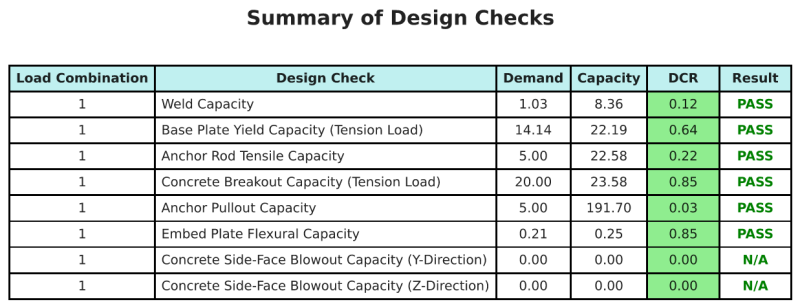
Περίληψη σχεδίου
ο Λογισμικό σχεδιασμού πλάκας βάσης SkyCIV Μπορεί να δημιουργήσει αυτόματα μια αναφορά υπολογισμού βήμα προς βήμα για αυτό το παράδειγμα σχεδιασμού. Παρέχει επίσης μια περίληψη των επιταγών που εκτελούνται και των προκύπτουσων αναλογιών τους, καθιστώντας τις πληροφορίες κατανοητές με μια ματιά. Παρακάτω είναι ένας πίνακας συνοπτικών δείγματος, που περιλαμβάνεται στην αναφορά.
Αναφορά δείγματος SkyCIV
Δείτε το επίπεδο λεπτομέρειας και σαφήνειας που μπορείτε να περιμένετε από μια αναφορά σχεδίασης πλάκας βάσης SkyCiv. Η αναφορά περιλαμβάνει όλους τους βασικούς ελέγχους σχεδιασμού, εξισώσεις, και τα αποτελέσματα παρουσιάζονται σε σαφή και ευανάγνωστη μορφή. Είναι πλήρως συμβατό με τα πρότυπα σχεδιασμού. Κάντε κλικ παρακάτω για να προβάλετε ένα δείγμα αναφοράς που δημιουργήθηκε με χρήση του SkyCiv Base Plate Calculator.
Αγορά λογισμικού πλάκας βάσης
Αγοράστε την πλήρη έκδοση της μονάδας σχεδιασμού πλάκας βάσης από μόνη της χωρίς άλλες ενότητες SkyCIV. Αυτό σας δίνει ένα πλήρες σύνολο αποτελεσμάτων για σχεδιασμό πλάκας βάσης, συμπεριλαμβανομένων λεπτομερών αναφορών και περισσότερων λειτουργιών.