Σε αυτό το άρθρο, θα σας καθοδηγήσουμε στον τρόπο προσδιορισμού του εδάφους ή των κατηγοριών έκθεσης στην αντίθετη πλευρά της τοποθεσίας του ιστότοπου, τα οποία είναι απαραίτητα για τον υπολογισμό των φορτίων ανέμου. Θα καλύψουμε τις συγκεκριμένες διαδικασίες που περιγράφονται στο ASCE 7, NBCC 2015, και AS / NZS 1170.2 για τον προσδιορισμό των κατηγοριών εδάφους και για να συζητήσετε πώς αυτές εφαρμόζονται σε κάθε κωδικό αναφοράς που είναι διαθέσιμος στο SkyCiv Load Generator.
ASCE 7-16/ASCE 7-22
Για την ASCE 7, η διαδικασία για τον προσδιορισμό της κατηγορίας έκθεσης της αντίθετης έκθεσης σε μια τοποθεσία τοποθεσίας συζητείται στην Ενότητα 26.7, ανάλογα με το έδαφος. Σε αυτό το άρθρο, για να απλοποιηθεί η αναφορά, θα χρησιμοποιήσουμε ASCE 7-16. Για κάθε κατεύθυνση πηγής ανέμου, θα πρέπει να αναλυθεί από δύο ανεμοδαρμένους τομείς που εκτείνονται ±45°.
Φιγούρα 1. Τομείς εδάφους για κάθε κατεύθυνση πηγής ανέμου.
Για κάθε τομέα, η κατηγορία τραχύτητας επιφάνειας θα πρέπει να ελεγχθεί με βάση τον ακόλουθο ορισμό με βάση την ενότητα 26.7.2 του ASCE 7-16:
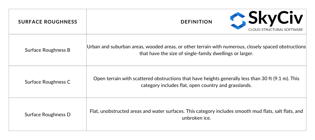
Τραπέζι 1. Ορισμός τραχύτητας επιφάνειας με βάση την ενότητα 26.7.2 του ASCE 7-16.
Από τον ορισμό της τραχύτητας επιφάνειας, μπορούμε να προσδιορίσουμε την Κατηγορία Έκθεσης του εδάφους που οριοθετείται από τον αντίθετο τομέα. Ο ορισμός για κάθε Κατηγορία Έκθεσης αναφέρεται στην Ενότητα 26.7.3 του ASCE 7-16 ως εξής:
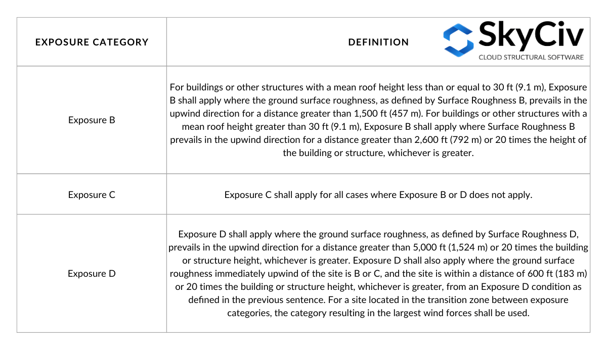
Τραπέζι 2. Ορισμός κατηγορίας έκθεσης με βάση την ενότητα 26.7.3 του ASCE 7-16.
Το τραπέζι 2 μπορεί να απεικονιστεί μέσω των παρακάτω σχημάτων με βάση την Εικόνα C26.7-2:
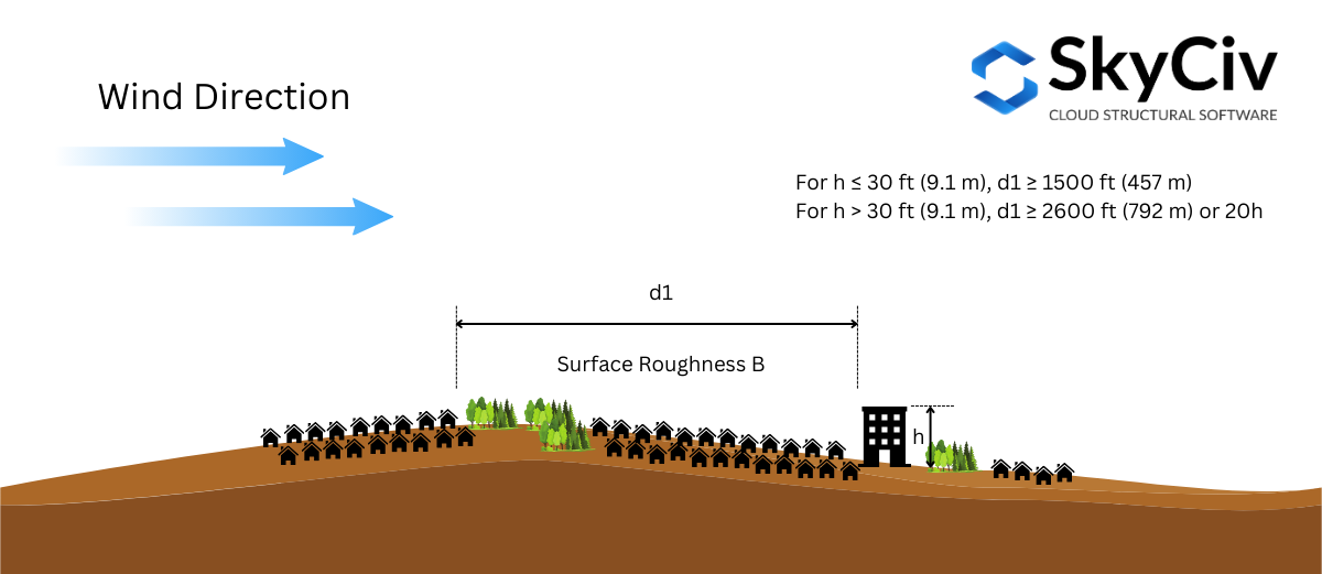
Φιγούρα 2. Απαιτούνται συνθήκες τραχύτητας αντίθετης επιφάνειας για την έκθεση B.
Φιγούρα 3. Απαιτείται συνθήκη τραχύτητας επιφάνειας αντίθετου ανέμου για την έκθεση D – συνδυάζοντας την επίδραση της εξωτερικής και εσωτερικής δράσης πίεσης 1.
Φιγούρα 4. Απαιτείται συνθήκη τραχύτητας επιφάνειας αντίθετου ανέμου για την έκθεση D – συνδυάζοντας την επίδραση της εξωτερικής και εσωτερικής δράσης πίεσης 2.
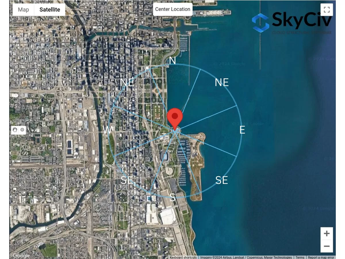
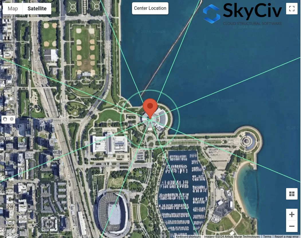
Η Κατηγορία Έκθεσης καθορίζεται για κάθε κατεύθυνση πηγής ανέμου. Χρησιμοποιώντας ένα παράδειγμα τοποθεσίας τοποθεσίας – “1200 S DuSable Lake Shore Dr, Σικάγο, Ο 60605, ΗΠΑ”, ας το αναλύσουμε για κάθε κατεύθυνση.
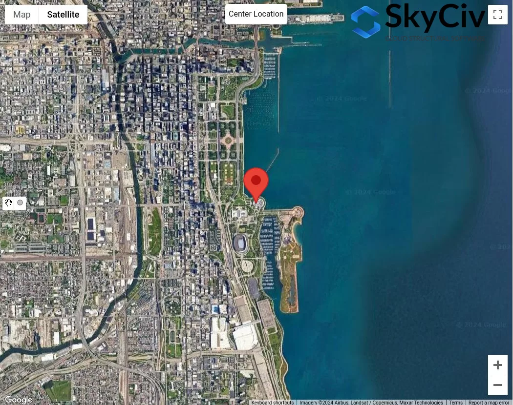
Φιγούρα 4. Δείγμα τοποθεσίας για ανάλυση κατηγορίας έκθεσης.
Υποθέτοντας ότι το μέσο ύψος στέγης της κατασκευής είναι 25 πόδια ( \( 20h = 500 πόδια \)), θα χρησιμοποιήσουμε την παρακάτω διαδικασία για να ελέγξουμε την Κατηγορία έκθεσης για κάθε τομέα:
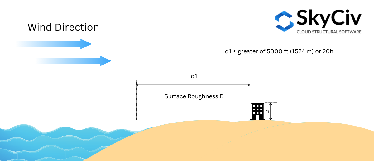
Κατάσταση 1. Προσδιορίστε εάν η έκθεση D χρησιμοποιώντας το Σχήμα 3:
Χρησιμοποιώντας το σχήμα 3 – όπου η απόσταση \( ρε_{1} \) είναι 5000 πόδια (1524 Μ), πρέπει να ελέγξουμε για την έκθεση D, όπου η επιφανειακή τραχύτητα D είναι κυρίαρχη για το σύνολο 5000 πόδια τέντωμα:
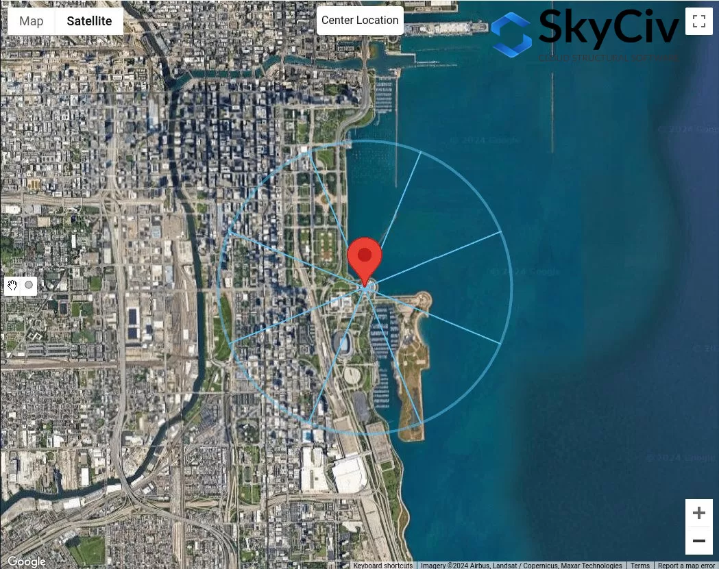
Φιγούρα 5. Απόσταση μετατόπισης του 5000 πόδια από τη θέση τοποθεσίας για έλεγχο έκθεσης D χρησιμοποιώντας το Σχήμα 3.
Από το σχήμα 5, μπορούμε ήδη να συμπεράνουμε ότι οι κατευθύνσεις πηγής ανέμου Ν, ΓΕΝΝΗΜΕΝΟΣ, και Ε έχουν τραχύτητα επιφάνειας D για το σύνολο 5000 πόδια τέντωμα. Επομένως, αυτές οι κατευθύνσεις πηγής ανέμου είναι Έκθεση Δ.
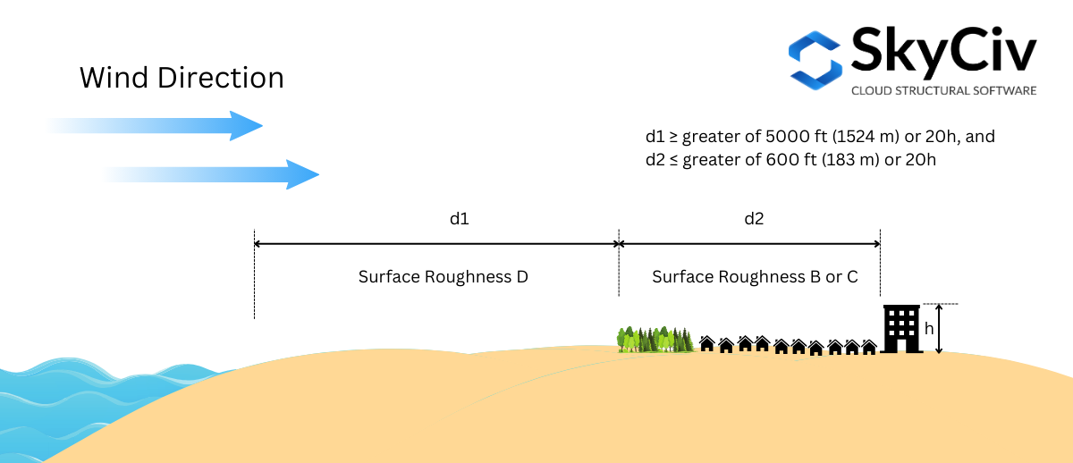
Κατάσταση 2. Προσδιορίστε εάν η έκθεση D χρησιμοποιώντας το Σχήμα 2
Χρησιμοποιώντας το σχήμα 4 – όπου η απόσταση \( ρε_{1} \) είναι 5000 πόδια (1524 Μ) και απόσταση \( ρε_{2} \) είναι ίσο με 600 πόδια (183 Μ), πρέπει να ελέγξουμε για την έκθεση D. Από το σχήμα 5, Αυτό μπορεί να εφαρμοστεί μόνο για κατεύθυνση πηγής ανέμου από ΝΑ:
Φιγούρα 6. Απόσταση όφσετ 600 πόδια και επιπλέον 5000 πόδια από τη θέση τοποθεσίας για έλεγχο έκθεσης D χρησιμοποιώντας το Σχήμα 4.
Για κατεύθυνση πηγής ανέμου ΝΑ, χρησιμοποιώντας \( ρε_{2} = 600 πόδια \), μπορούμε να θεωρήσουμε ότι αυτό το τμήμα είναι Τραχύτητα Επιφάνειας Β. Ωστόσο, για απόσταση \( ρε_{1} = 5000 πόδια \), το τμήμα δεν είναι 100% Τραχύτητα επιφάνειας Δ. Ως εκ τούτου, Η SE δεν θα πρέπει να θεωρείται ως έκθεση Δ.
Κατάσταση 3. Προσδιορίστε εάν η έκθεση Β χρησιμοποιώντας το σχήμα 1
Χρησιμοποιώντας το σχήμα 3 – όπου η απόσταση \( ρε_{1} \) είναι 1500 πόδια (457 Μ) Από \( η < 30 πόδια \), πρέπει να ελέγξουμε για την έκθεση Β.
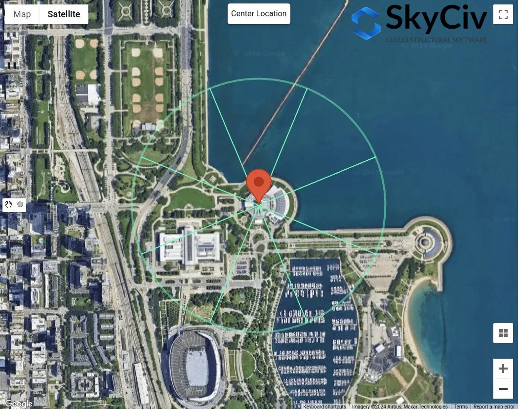
Φιγούρα 7. Απόσταση μετατόπισης του 1500 πόδια από τη θέση τοποθεσίας για έλεγχο έκθεσης Β χρησιμοποιώντας το Σχήμα 3.
Από το σχήμα 7, μπορούμε να προσδιορίσουμε ότι για τις κατευθύνσεις πηγής ανέμου ΒΔ, Δ, ΝΔ, και το S ταξινομούνται ως Έκθεση Β καθώς η τραχύτητα επιφάνειας για κάθε τομέα κατεύθυνσης είναι Τραχύτητα επιφάνειας Β.
Κατάσταση 4. Εάν προϋποθέσεις 1 προς το 3 δεν είναι αλήθεια, επομένως, το έδαφος είναι έκθεσης C.
Επομένως, για κατεύθυνση πηγής ανέμου ΝΑ, ταξινομείται στην κατηγορία έκθεσης Γ. Συνοψίζοντας, Οι κατηγορίες έκθεσης για κάθε κατεύθυνση πηγής ανέμου φαίνονται στο σχήμα 8 παρακάτω.
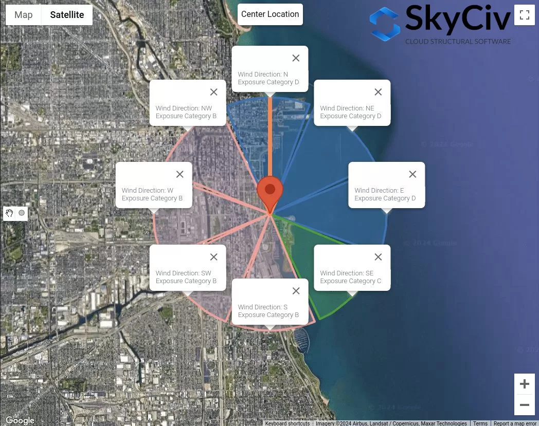
Φιγούρα 8. Οι κατηγορίες έκθεσης για κάθε κατεύθυνση πηγής ανέμου.
Αυτά τα δεδομένα μπορούν να χρησιμοποιηθούν για να προσδιοριστεί ποια θα είναι η χειρότερη κατεύθυνση της πηγής ανέμου όπως οι συντελεστές πίεσης ταχύτητας \( Κ_{με} \), Τοπογραφικός παράγοντας \( Κ_{τ} \), και Gust-effect Factor \( σολ \) χρησιμοποιώντας λεπτομερή υπολογισμό επηρεάζονται από την Κατηγορία έκθεσης.
NBCC 2015/2020
Για το NBCC 2015, η διαδικασία για τον προσδιορισμό της κατηγορίας έκθεσης της αντίθετης έκθεσης σε μια τοποθεσία τοποθεσίας συζητείται στην Ενότητα 4.1.7.3(5), ανάλογα με το έδαφος. Για κάθε κατεύθυνση πηγής ανέμου, θα πρέπει να αναλυθεί από δύο ανεμοδαρμένους τομείς που εκτείνονται ±45°.
Φιγούρα 9. Τομείς εδάφους για κάθε κατεύθυνση πηγής ανέμου.
Για κάθε τομέα, η κατηγορία του εδάφους θα πρέπει να ελέγχεται με βάση τον ακόλουθο ορισμό με βάση την Ενότητα 4.1.7.3(5) του NBCC 2015:
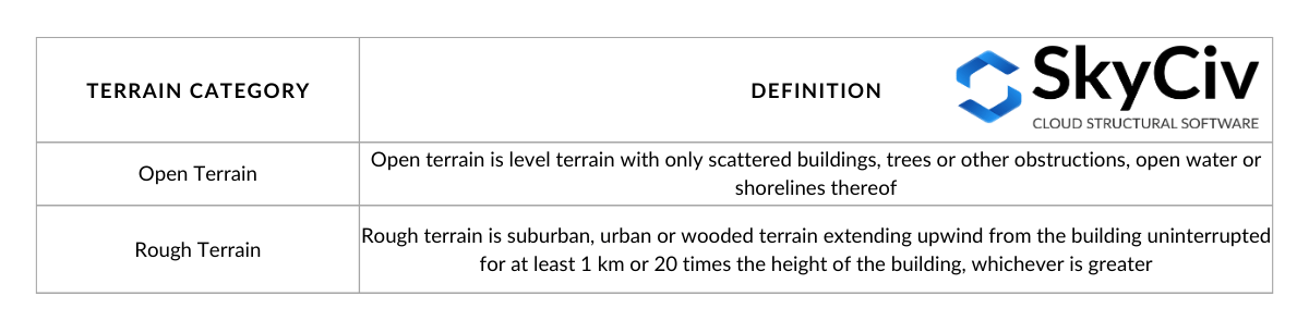
Τραπέζι 3. Ορισμός κατηγοριών εδάφους όπως ορίζονται στην Ενότητα 4.1.7.3(5) του NBCC 2015.
Οπτικοποίηση των επιλογών στον Πίνακα 3:
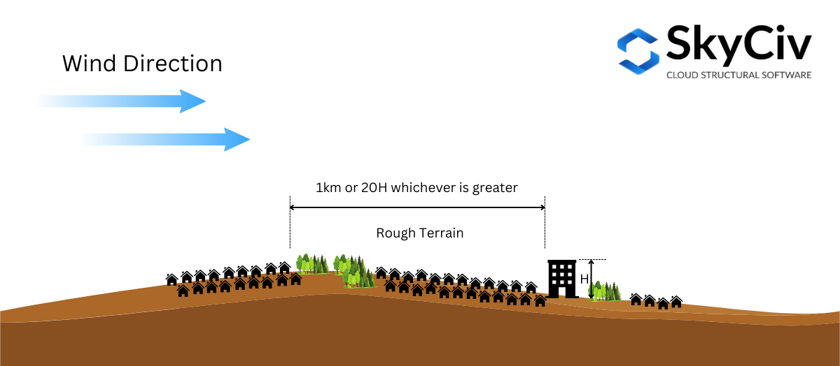
Φιγούρα 10. Ορισμός ανώμαλου εδάφους όπως ορίζεται στην ενότητα 4.1.7.3(5) του NBCC 2015.
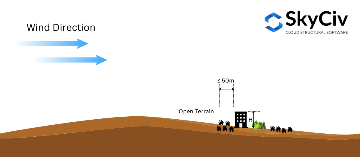
Φιγούρα 10. Ορισμός ανοιχτού εδάφους όπως ορίζεται στην ενότητα 4.1.7.3(5) του NBCC 2015.
Με βάση την Ενότητα 4.1.7.3(5) του NBCC 2015, επιτρέπεται η παρεμβολή του Συντελεστής έκθεσης \( ΝΤΟ_{μι} \) σε ενδιάμεσο έδαφος. Εάν η απόσταση ανώμαλου εδάφους από τη θέση της κατασκευής είναι μεγαλύτερη ή ίση με 1 km ή 20 φορές το ύψος της δομής, όποιο είναι μεγαλύτερο, το έδαφος μπορεί να θεωρηθεί ως Ανώμαλο Έδαφος, και αν η απόσταση είναι μικρότερη από 50 Μ, θεωρείται ως Ανοιχτό Έδαφος. Σε διαφορετική περίπτωση, ο παράγοντας έκθεσης \( ΝΤΟ_{μι} \) σύμφωνα με την Ενότητα 4.1.7.3(5) θα υπολογιστεί από τις οριακές τιμές. Αυτό μπορεί να απεικονιστεί στο Σχήμα 11 παρακάτω.
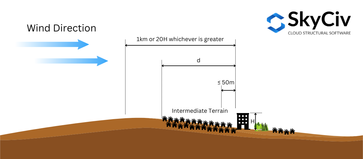
Φιγούρα 11. Ορισμός Ενδιάμεσου Εδάφους όπως ορίζεται στην Ενότητα 4.1.7.3(5) του NBCC 2015.
Για να το διευκρινίσουμε περαιτέρω, Ας χρησιμοποιήσουμε ένα παράδειγμα τοποθεσίας ιστότοπου – “657 Masters Rd SE, Κάλγκαρι, AB T3M 2B6, Καναδάς,” υποθέτοντας το ύψος της δομής \( Η \) είναι 25 Μ ( \( 20H = 500 Μ \)).
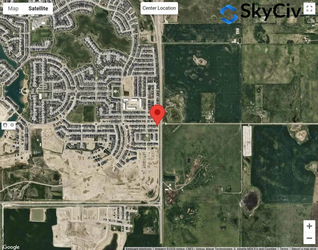
Φιγούρα 12. Δείγμα τοποθεσίας για ανάλυση Κατηγορίας Εδάφους.
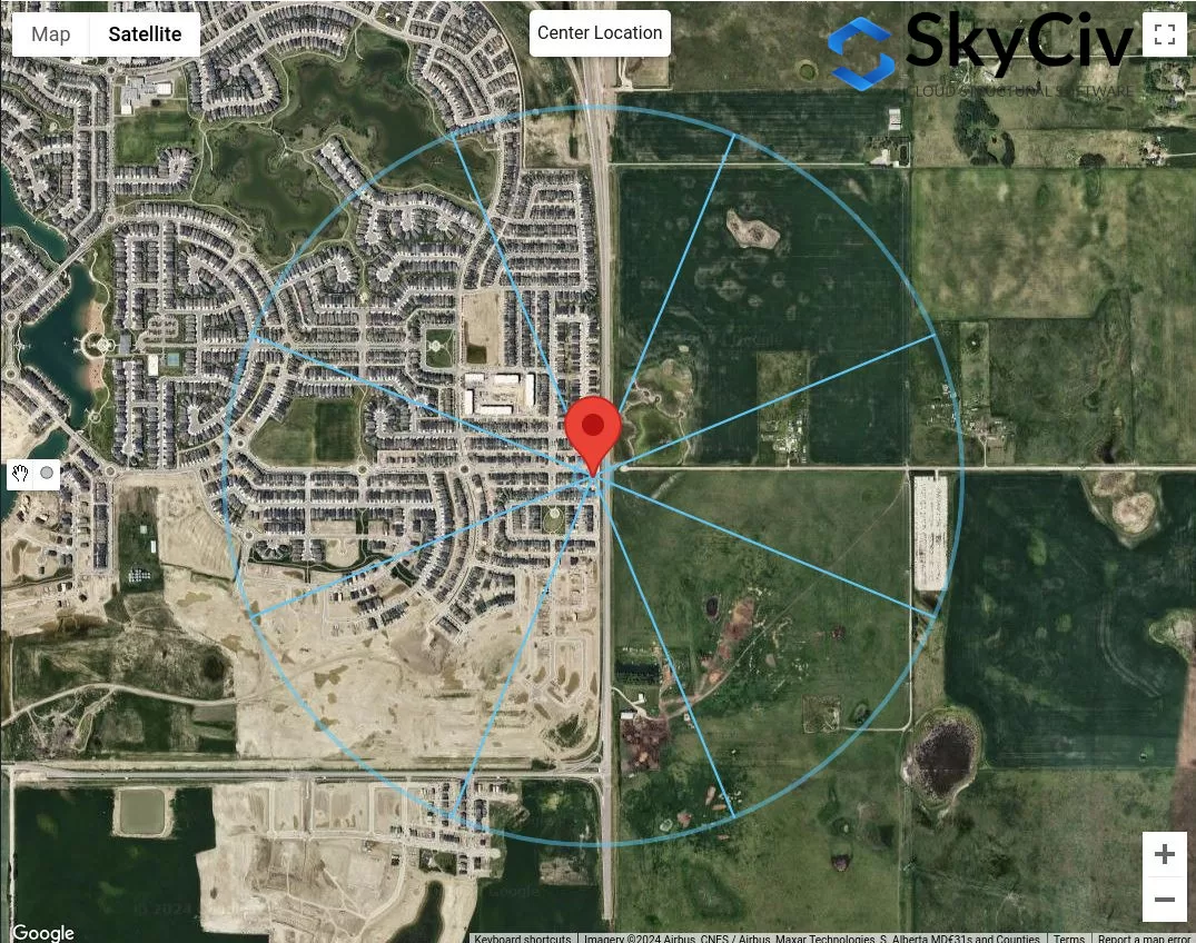
Το πρώτο βήμα είναι η ταξινόμηση των προφανών κατηγοριών ανώμαλου και ανοιχτού εδάφους για κάθε κατεύθυνση πηγής ανέμου. Μπορούμε να τραβήξουμε 50μ και μέγιστο 1 χλμ ή \( 20 Η \) ακτίνα από την τοποθεσία της τοποθεσίας.
Φιγούρα 13. Απόσταση offset 50m και 1km για τον προσδιορισμό της κατηγορίας εδάφους βάσει Πίνακα 1 ορισμούς.
Από το σχήμα 13, μπορούμε να πούμε ότι οι κατευθύνσεις πηγής ανέμου ΓΕΝΝΗΜΕΝΟΣ, μι, και SE ταξινομούνται ως Ανοιχτό έδαφος καθώς το μήκος ανώμαλου εδάφους για κάθε κατεύθυνση είναι μικρότερο από 50 μέτρα από την τοποθεσία της τοποθεσίας. Εξάλλου, για τις κατευθύνσεις των πηγών ανέμου Δ και ΒΔ μπορεί να ταξινομηθεί ως Ανώμαλο Έδαφος καθώς το μήκος του ανώμαλου εδάφους για αυτές τις κατευθύνσεις είναι μεγαλύτερο από 1 χιλιόμετρα. Για την κατεύθυνση της πηγής ανέμου Ν, μπορούμε συντηρητικά να υποθέσουμε ότι το Ανοιχτό Έδαφος είναι κυρίαρχο προς αυτή την κατεύθυνση. Για τα υπόλοιπα, Ν και ΝΔ, μπορούμε να συμπεράνουμε ότι πρόκειται για ενδιάμεσο έδαφος και θα χρειαστεί να μετρήσουμε την απόσταση του ανώμαλου εδάφους από την τοποθεσία της τοποθεσίας.
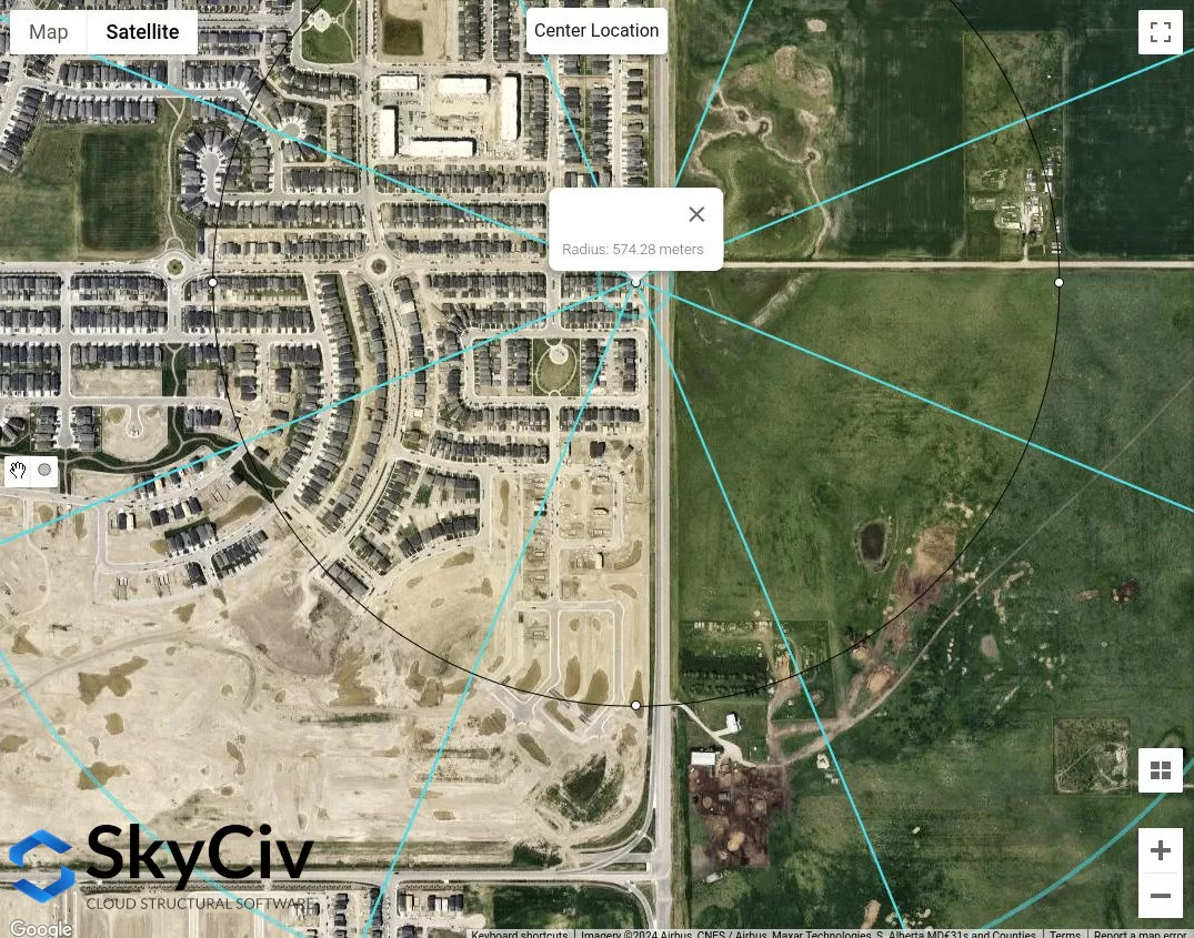
Φιγούρα 14. Κατά προσέγγιση μήκος ανώμαλου εδάφους μετρούμενο από την τοποθεσία τοποθεσίας για κατεύθυνση πηγής ΝΔ ανέμου ίσο με 574 Μ.
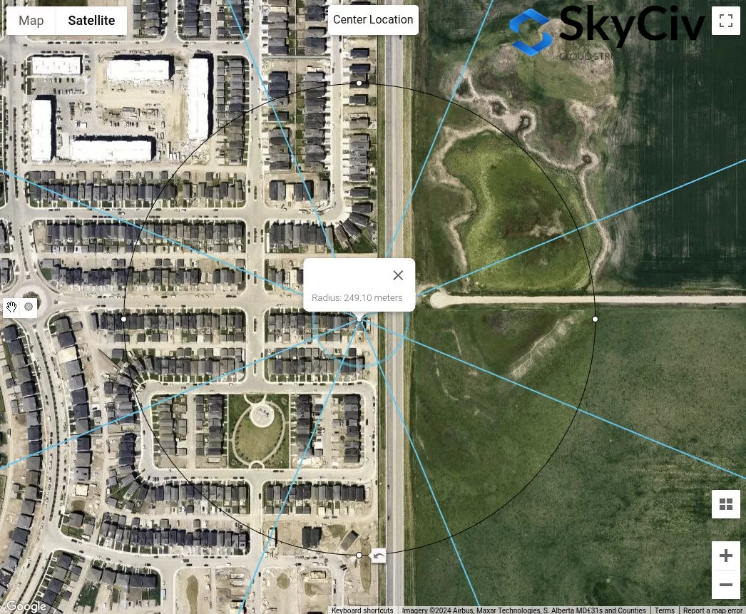
Φιγούρα 15. Κατά προσέγγιση μήκος ανώμαλου εδάφους που μετράται από τη θέση της τοποθεσίας για κατεύθυνση πηγής ανέμου Ν ίση με 249 Μ.
Από την παραπάνω ανάλυση, Σίγουρα οι κατευθύνσεις της πηγής ανέμου με το Open Terrain θα αποδώσουν σίγουρα τις συντηρητικές τιμές. Ωστόσο, εάν όλες οι κατευθύνσεις των πηγών ανέμου ταξινομούνται σε Ενδιάμεσο Έδαφος, Η παραπάνω διαδικασία είναι πώς μπορείτε να προσδιορίσετε την κατάλληλη Κατηγορία Εδάφους για κάθε κατεύθυνση.
AS / NZS 1170.2 (2021)
Για AS / NZS 1170.2, η ίδια διαδικασία με τις παραπάνω παραπομπές ισχύει για τον προσδιορισμό της Κατηγορίας Εδάφους της αντίθετης έκθεσης σε μια τοποθεσία τοποθεσίας. Αυτό συζητείται στην Ενότητα 4.2 του AS / NZS 1170.2 (2021). Για κάθε κατεύθυνση πηγής ανέμου, θα πρέπει να αναλυθεί από δύο ανεμοδαρμένους τομείς που εκτείνονται ±45°. Ο ορισμός κάθε κατηγορίας εδάφους φαίνεται παρακάτω με βάση την Ενότητα 4.2.1 του AS / NZS 1170.2 (2021):
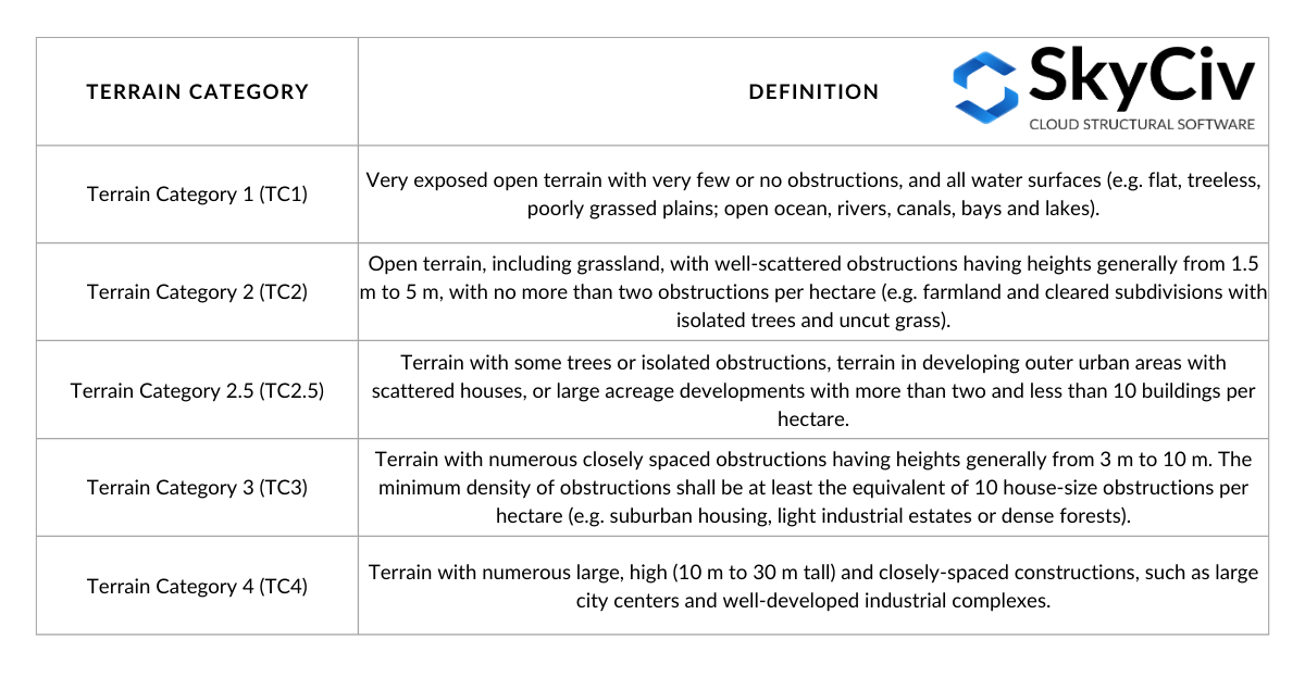
Τραπέζι 4. Ορισμός κατηγοριών εδάφους όπως ορίζονται στην Ενότητα 4.2.1 του AS / NZS 1170.2 (2021).
Στον προσδιορισμό της κατηγορίας εδάφους για μια κατεύθυνση, απόσταση υστέρησης ίση με \( 20 με \) από τη θέση της δομής θα πρέπει να παραμεληθεί. Από αυτό το σημείο, μια απόσταση μετατόπισης (μέση απόσταση) του 500 m ή \( 40 z), όποιο είναι μεγαλύτερο, θα χρησιμοποιηθεί όπως φαίνεται στο σχήμα 16 παρακάτω. ο \( με \) τιμή είναι ίση με το μέσο ύψος στέγης, \( η \), όταν είναι μικρότερο ή ίσο με 25 Μ. Είναι πιθανό εντός αυτής της μέσης απόστασης να υπάρχουν πολλαπλές κατηγορίες εδάφους, και ως τέτοια, γραμμική παρεμβολή του θα χρησιμοποιηθεί για τον προσδιορισμό του \( Μ_{με,Γάτα} \) αξίες, ανάλογα με το μήκος κάθε κατηγορίας εδάφους, όπως απεικονίζεται στο Σχήμα 4.1 του AS / NZS 1170.2 (2021). Σε αυτό το άρθρο, Θα εξετάσουμε μόνο μια κατηγορία ομοιογενούς εδάφους εντός της μέσης απόστασης.
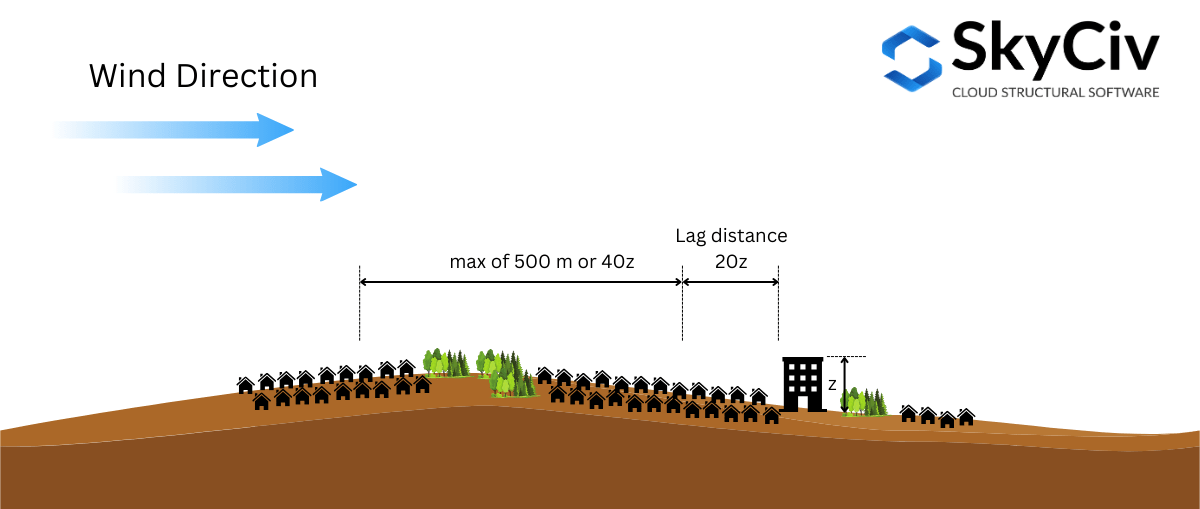
Φιγούρα 16. Απεικόνιση των αποστάσεων που χρησιμοποιούνται για τον προσδιορισμό της Κατηγορίας Εδάφους βάσει AS/NZS 1170.2 (2021).
Για να το διευκρινίσουμε περαιτέρω, Ας χρησιμοποιήσουμε ένα παράδειγμα τοποθεσίας ιστότοπου – Lat: 32°43’46″S Lang: 151°31’47″μι – υποθέτοντας το μέσο ύψος στέγης \( η \) είναι 10 Μ ( όπου \( 20z = 20h = 200 Μ \) και \( 40z = 400 Μ \)).
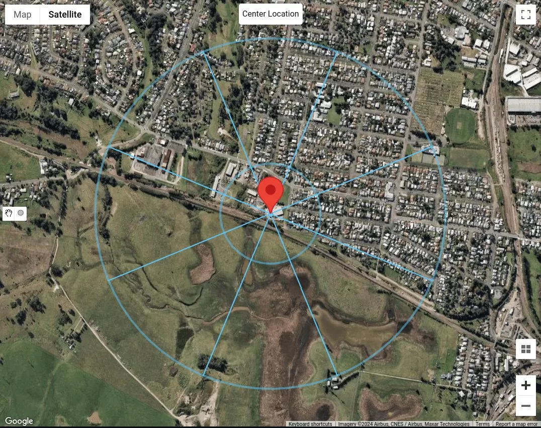
Φιγούρα 17. Η τοποθεσία του ιστότοπου με απόσταση υστέρησης ίση με 200 m και μέση απόσταση ίση με 500 m για κάθε κατεύθυνση πηγής ανέμου.
Δεδομένου ότι πρόκειται να θεωρήσουμε μόνο την κατηγορία εδάφους ως ομοιογενή σε όλο το μήκος των 500 μέτρων ή \( 40με \) απόσταση, μπορούμε ήδη να ταξινομήσουμε κάθε κατεύθυνση πηγής ανέμου. Υποθέτοντας ότι τα κτίρια στο Ν, ΝΕ και Ε, είναι κτίρια που είναι 5 προς το 10 ύψος, μπορούμε να τα ταξινομήσουμε στην Κατηγορία Εδάφους 3 (TC3) Το αποτέλεσμα της εν λόγω διαδικασίας είναι η αξιολόγηση ατομικού κινδύνου 4. Για κατευθύνσεις πηγής ανέμου ΝΑ, μικρό, ΝΔ, και W, αφού πρόκειται για χλοοτάπητες χωρίς εμπόδια, μπορούμε να τα ταξινομήσουμε ως Κατηγορία Εδάφους 1 (TC1). Τελικά, για κατεύθυνση πηγής ανέμου ΒΔ, μπορούμε να συμπεράνουμε ότι υπάρχουν περισσότερα από δύο αλλά λιγότερα από 10 κτίρια ανά εκτάριο, με διάσπαρτα σπίτια. Επομένως, μπορούμε να το ταξινομήσουμε ως Κατηγορία Εδάφους 2.5 (TC2.5).
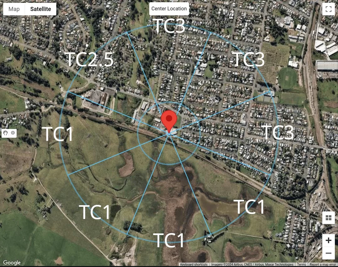
Φιγούρα 18. Σύνοψη της ταξινόμησης κατηγορίας εδάφους για κάθε κατεύθυνση πηγής ανέμου για τη θέση του δείγματός μας.
Χρήση του SkyCiv Load Generator
Στην έκδοση 4.7.0 του SkyCiv Load Generator, παρουσιάζονται νέα εργαλεία χαρτών – Μετρήστε την απόσταση και Ακτίνες απόστασης εργαλεία.
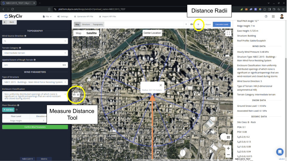
Φιγούρα 19. Εισάχθηκαν εργαλεία μέτρησης απόστασης στο SkyCiv Load Generator.
ο Μετρήστε την απόσταση Το εργαλείο χρησιμοποιείται για τη δημιουργία ενός κύκλου από ένα σημείο του χάρτη στο οποίο γίνεται κλικ και δείχνει την ακτίνα του σε μέτρα. Με αυτόν τον τρόπο, μπορείτε να μετρήσετε τις αποστάσεις από την τοποθεσία που αναλύεται τις συγκεκριμένες τοποθεσίες. Αυτό μπορεί να χρησιμοποιηθεί στη μέτρηση σε NBCC 2015 για το Ανεμοδαρμένη έκταση ανώμαλου εδάφους χρησιμοποιείται στον υπολογισμό Συντελεστής έκθεσης \( ΝΤΟ_{μι} \). Κάνοντας κλικ στον κύκλο που δημιουργείται θα διαγραφεί από τον χάρτη.
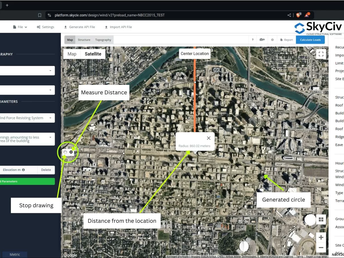
Φιγούρα 20. Εργαλείο μέτρησης απόστασης που δημιουργεί μια μετατόπιση από την τοποθεσία και δείχνει την απόσταση ακτίνας/απόστασης από το κέντρο που εισάγεται στο SkyCiv Load Generator.
Αφ 'ετέρου, ο Ακτίνες απόστασης εισάγεται έτσι ώστε οι χρήστες να μπορούν να σχεδιάζουν κύκλους με καθορισμένες αποστάσεις από την τοποθεσία για κάθε κατηγορία πηγών ανέμου. Είναι ένα κουμπί εναλλαγής για εμφάνιση ή απόκρυψη των ακτίνων απόστασης στον χάρτη, με την τοποθεσία του ιστότοπου ως κέντρο των κύκλων.
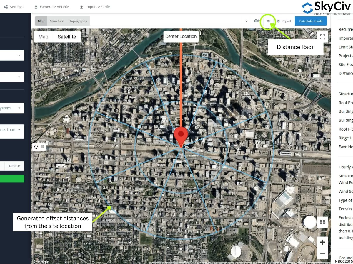
Φιγούρα 21. Εργαλείο Distance Radii που καθόριζε αποστάσεις μετατόπισης από την τοποθεσία του ιστότοπου που εισήχθη στο SkyCiv Load Generator.
Οι τιμές των ακτίνων μπορούν να τροποποιηθούν με το άνοιγμα των Ρυθμίσεων.
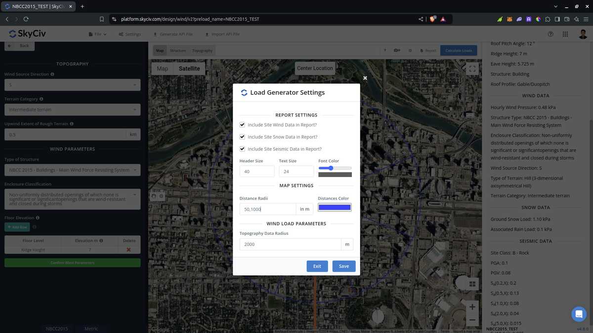
Φιγούρα 22. Επιλογή στις ρυθμίσεις για να επεξεργαστείτε τις αποστάσεις για το εργαλείο Distance Radii στο SkyCiv Load Generator.
Λάβετε υπόψη ότι οι χρήστες πρέπει να επεξεργαστούν τις τιμές απόστασης καθώς αυτές δεν υπολογίζονται αυτόματα από το λογισμικό. Χρησιμοποιώντας αυτό για ASCE 7 και NBCC, υιοθετείται η χειρότερη κατηγορία έκθεσης ή εδάφους για κάθε κατεύθυνση πηγής ανέμου. Όσον αφορά τη χρήση του στο AS/NZS 1170.2 (2021), το λογισμικό δεν χρησιμοποιεί τις τιμές των ακτίνων για τον υπολογισμό του μέσου όρου \( Μ_{με,Γάτα} \) αξίες. αντι αυτου, η μέση απόσταση χρησιμοποιείται ως το εφαρμοστέο εύρος όπου μπορούμε να εκχωρήσουμε μια ομοιογενή Κατηγορία Εδάφους, υιοθετώντας τη χειρότερη κατηγορία για κάθε κατεύθυνση πηγής ανέμου.
Από τις ενότητες που συζητήθηκαν παραπάνω, μπορείτε να χρησιμοποιήσετε αυτά τα νέα εργαλεία για να προσδιορίσετε τις κατηγορίες έκθεσης ή εδάφους για κάθε κατεύθυνση πηγής ανέμου. Οι παραπάνω διαδικασίες μπορούν να σας δώσουν μια γρήγορη ταξινόμηση του εδάφους για κάθε κατεύθυνση πηγής ανέμου. Χρήση εργαλείων GIS και AI, μπορείτε να ελέγξετε περαιτέρω τα κριτήρια που χρησιμοποιήσαμε παραπάνω για κάθε κατεύθυνση πηγής ανέμου και να έχετε ένα καλύτερο και αποτελεσματικό αποτέλεσμα.

Δομικός μηχανικός, Ανάπτυξη προϊόντων
MS Πολιτικών Μηχανικών
βιβλιογραφικές αναφορές:
- Ελάχιστα φορτία σχεδιασμού για κτίρια και άλλες κατασκευές. (2017). ΑΞΟΝΕΣ / ΕΞΙ 7-16. Αμερικανική Εταιρεία Πολιτικών Μηχανικών.
- Εθνικό Συμβούλιο Έρευνας του Καναδά. (2015). Εθνικός Κώδικας του Καναδά, 2015. Εθνικό Συμβούλιο Έρευνας του Καναδά.
- Πρότυπα Αυστραλία (2021), Δράσεις Στατικής Σχεδιασμού. Μέρος 2 Δράσεις ανέμου, Πρότυπο Αυστραλίας/Νέας Ζηλανδίας AS/NZS1170.2:2021, Πρότυπα Αυστραλία, Σίδνεϊ, NSW, Αυστραλία.
- = Απόσταση αντίθετα από τον άνεμο της κορυφής μέχρι όπου η διαφορά στο υψόμετρο του εδάφους είναι το μισό του ύψους του λόφου ή του λόφου