Esempio di design della piastra di base usando CSA S16:19 e CSA A23.3:19
Dichiarazione del problema
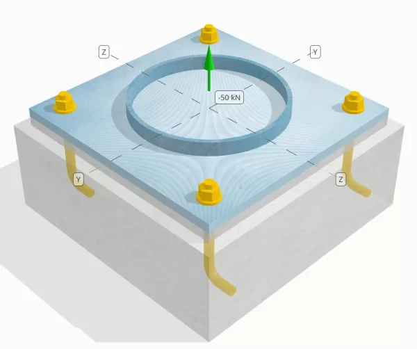
Determina se la connessione a piastra da colonna a base progettata è sufficiente per un carico di tensione da 50 kn.
Dati dati
Colonna:
Sezione colonna: HS324x9.5
Area colonna: 9410 mm2
Materiale colonna: 230sol
Piastra di base:
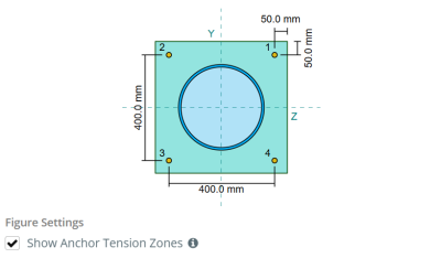
Dimensioni della piastra di base: 500 mm x 500 mm
Spessore della piastra di base: 20 mm
Materiale della piastra di base: 230sol
Malta:
Spessore di malta: 20 mm
Calcestruzzo:
Dimensioni concrete: 550 mm x 550 mm
Spessore di cemento: 200 mm
Materiale di cemento: 20.68 MPa
Crackato o non collocato: Rotto
Ancore:
Diametro dell'ancora: 19.1 mm
Efficace lunghezza dell'incorporamento: 130.0 mm
Lunghezza del gancio: 60mm
Ancora la distanza di offset dalla faccia della colonna: 120.84 mm
saldature:
Tipo di saldatura: CJP
Classificazione del metallo di riempimento: E43xx
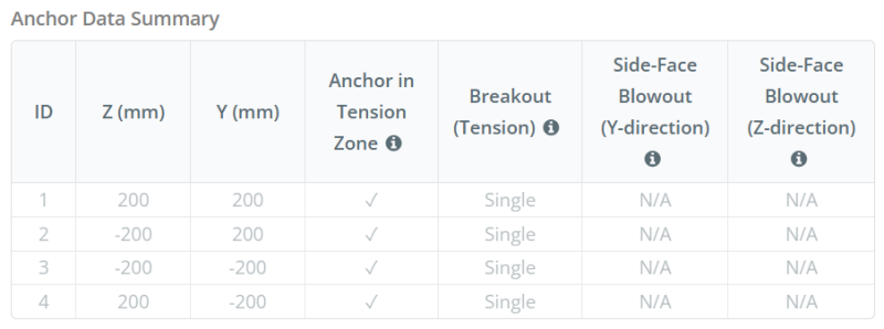
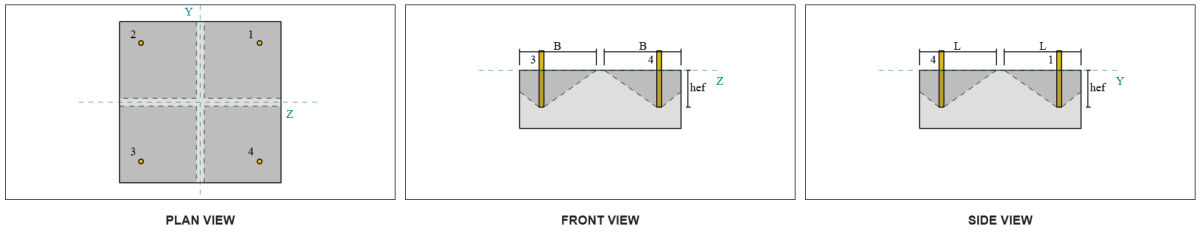
Dati di ancoraggio (a partire dal Calcolatore Skyciv):
Modello nello strumento gratuito SkyCiv
Modella il design della piastra di base qui sopra utilizzando il nostro strumento online gratuito oggi stesso! Non è richiesta la registrazione.
Definizioni
Percorso di carico:
Quando una piastra di base è sottoposta a sollevamento (trazione) forze, Queste forze vengono trasferite alle aste di ancoraggio, che a loro volta inducono momenti di flessione nella piastra di base. L'azione di piegatura può essere visualizzata come flessione a sbalzo che si verifica attorno alle flange o alla rete della sezione colonna, a seconda di dove sono posizionati gli ancori.
Nel Software di progettazione della piastra di base Skyciv, solo ancore situati all'interno del zona di tensione di ancoraggio sono considerati efficaci nel resistere al sollevamento. Questa zona include in genere le aree vicino alle flange di colonna o al web. Nel caso di a colonna circolare, La zona di tensione di ancoraggio include l'intera area al di fuori del perimetro della colonna. Le ancore al di fuori di questa zona non contribuiscono alla resistenza alla tensione e sono esclusi dai calcoli di sollevamento.
Per determinare l'area efficace della piastra di base che resiste alla flessione, un carico 45-Dispersione di laurea è ipotizzato dalla linea centrale di ogni asta di ancoraggio verso la faccia della colonna. Questa dispersione definisce il Efficace lunghezza della saldatura e aiuta a stabilire il larghezza di flessione efficace del piatto.
L'Assunzione semplifica l'analisi della piastra di base approssimando il modo in cui la forza di sollevamento si diffonde attraverso la piastra.
Gruppi di ancoraggio:
La Software di progettazione della piastra di base Skyciv Include una caratteristica intuitiva che identifica quali ancore fanno parte di un gruppo di ancoraggio per la valutazione rottura concreta e Blowout della faccia laterale in cemento fallimenti.
Un gruppo di ancoraggio è costituito da più ancore con profondità di incorporamento e spaziatura simili, e sono abbastanza vicini che il loro Le aree di resistenza proiettate si sovrappongono. Quando le ancore sono raggruppate, Le loro capacità sono combinate per resistere alla forza di tensione totale applicata al gruppo.
Le ancore che non soddisfano i criteri di raggruppamento sono trattati come ancore singole. In questo caso, Solo la forza di tensione sull'ancoraggio individuale è controllata contro la propria area di resistenza efficace.
Calcoli passo-passo
Dai un'occhiata #1: Calcola la capacità di saldatura
Iniziare, Dobbiamo calcolare il carico per ancoraggio e determinare la lunghezza di saldatura effettiva per ciascun ancoraggio. La Efficace lunghezza della saldatura si basa su a 45° linea di dispersione tratto dal centro dell'ancora alla faccia della colonna. Se questa linea a 45 ° non interseca la colonna, il punti tangenti sono invece usati. Inoltre, Se gli ancori sono strettamente distanziati, La lunghezza efficace della saldatura è ridotta per evitare la sovrapposizione. Infine, La somma di tutte le lunghezze di saldatura efficaci non deve superare la lunghezza saldabile effettiva disponibile lungo la circonferenza della colonna.
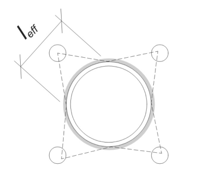
Applichiamo questo al nostro esempio. Basato sulla geometria data, La linea a 45 ° dall'ancora non interseca la colonna. Di conseguenza, invece viene utilizzata la lunghezza dell'arco tra i punti tangenti. Questa lunghezza dell'arco deve anche tenere conto di eventuali ancoraggi adiacenti, con qualsiasi porzione sovrapposta sottratta per evitare il doppio conteggio. La lunghezza dell'arco calcolato è:
\(
l_{\testo{arco}} = 254.47 \, \testo{mm}
\)
Questo calcolo della lunghezza dell'arco è completamente automatizzato nel software di progettazione della piastra di base Skyciv, ma può anche essere eseguito manualmente usando metodi trigonometrici. Puoi provare lo strumento gratuito da questo link.
Considerando la lunghezza saldabile disponibile lungo la circonferenza della colonna, il finale Efficace lunghezza della saldatura è:
\(
l_{\testo{eff}} = min sinistra( l_{\testo{arco}}, \frac{\pi d_{\testo{col}}}{N_{un carico,t}} \giusto) = min sinistra( 254.47 \, \testo{mm}, \frac{\pi volte 324 \, \testo{mm}}{4} \giusto) = 254.47 \, \testo{mm}
\)
Successivamente, Calcoliamo il Carica per ancora. Per un determinato set di quattro (4) ancore, Il carico per ancoraggio è:
\(
T_{u,\testo{ancorare}} = frac{N_x}{N_{un carico,t}} = frac{50 \, \testo{kN}}{4} = 12.5 \, \testo{kN}
\)
Utilizzando la lunghezza di saldatura effettiva calcolata, ora possiamo calcolare il forza richiesta per unità di lunghezza recitare sulla saldatura.
\(
v_f = frac{T_{u,\testo{ancorare}}}{l_{\testo{eff}}} = frac{12.5 \, \testo{kN}}{254.47 \, \testo{mm}} = 0.049122 \, \testo{metri ed è fissato alla base e fissato in alto}
\)
Adesso, ci riferiamo a CSA S16:19 Clausola 13.13.3.1 per calcolare il Resistenza pressurata della penetrazione completa dell'articolazione (CJP) saldare. Ciò richiede la resistenza al metallo di base, espresso in vigore per unità di lunghezza, sia per la colonna che per i materiali della piastra di base.
\(
v_{r,\testo{bm}} = phi a sinistra( \min a sinistra( F_{y,\testo{col}} t_{\testo{col}}, F_{y,\testo{p.p}} t_{\testo{p.p}} \giusto) \giusto)
\)
\(
v_{r,\testo{bm}} = 0.9 \volte sinistra( \min a sinistra( 230 \, \testo{MPa} \volte 9.53 \, \testo{mm}, 230 \, \testo{MPa} \volte 20 \, \testo{mm} \giusto) \giusto) = 1.9727 \, \testo{metri ed è fissato alla base e fissato in alto}
\)
Da 0.049122 metri ed è fissato alla base e fissato in alto < 1.9727 metri ed è fissato alla base e fissato in alto, La capacità di saldatura è sufficiente.
Dai un'occhiata #2: Calcola la capacità di cedimento della flessione della piastra di base dovuta al carico di tensione
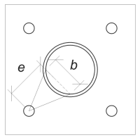
Usando il carico per ancoraggio e il distanza di offset dal centro dell'ancora alla faccia della colonna, Il momento applicato alla piastra di base può essere calcolato usando a a sbalzo assunzione. Per una colonna circolare, L'eccentricità del carico viene determinata considerando la sagitta dell'arco saldato, e può essere calcolato come segue:
\(
e_{\testo{tubo}} = d_o + r_{\testo{col}} \sinistra( 1 – \cos sinistra( \frac{l_{\testo{eff}}}{2 r_{\testo{col}}} \giusto) \giusto)
\)
\(
e_{\testo{tubo}} = 120.84 \, \testo{mm} + 162 \, \testo{mm} \volte sinistra( 1 – \cos sinistra( \frac{254.47 \, \testo{mm}}{2 \volte 162 \, \testo{mm}} \giusto) \giusto) = 168.29 \, \testo{mm}
\)
Il momento indotto viene calcolato come:
\(
M_f = t_{u,\testo{ancorare}} e_{\testo{tubo}} = 12.5 \, \testo{kN} \volte 168.29 \, \testo{mm} = 2103.6 \, \testo{kN} \CDOT text{mm}
\)
Successivamente, Determineremo la larghezza di flessione della piastra di base. Per questo, Usiamo il lunghezza dell'accordo corrispondente all'arco di saldatura efficace.
\(
\theta_{\testo{lavoro}} = frac{l_{\testo{eff}}}{0.5 d_{\testo{col}}} = frac{254.47 \, \testo{mm}}{0.5 \volte 324 \, \testo{mm}} = 1.5708
\)
\(
b = d_{\testo{col}} \sinistra( \peccato sinistra( \frac{\theta_{\testo{lavoro}}}{2} \giusto) \giusto) = 324 \, \testo{mm} \volte sinistra( \peccato sinistra( \frac{1.5708}{2} \giusto) \giusto) = 229.1 \, \testo{mm}
\)
Infine, Possiamo calcolare il preso in considerazione Resistenza alla flessione della piastra di base usando CSA S16:19 Clausola 13.5.
\(
M_r = phi f_{y,\testo{p.p}} Z_{\testo{eff}} = 0.9 \volte 230 \, \testo{MPa} \volte 22910 \, \testo{mm}^3 = 4742.4 \, \testo{kN} \CDOT text{mm}
\)
Dove,
\(
Z_{\testo{eff}} = frac{b (t_{\testo{p.p}})^ 2}{4} = frac{229.1 \, \testo{mm} \volte (20 \, \testo{mm})^ 2}{4} = 22910 \, \testo{mm}^ 3
\)
Da 2103.6 kn-mm < 4742.4 kn-mm, La capacità di cessione di flessione della piastra di base è sufficiente.
Dai un'occhiata #3: Calcola la capacità di trazione dell'asta di ancoraggio
Per valutare la capacità di trazione dell'asta di ancoraggio, ci riferiamo a CSA A23.3:19 Clausola D.6.1.2 e CSA S16:19 Clausola 25.3.2.1.
Primo, Determiniamo il forza di trazione specificata dell'acciaio di ancoraggio. Questo è il valore più basso consentito da CSA A23.3:19 Clausola D.6.1.2.
\(
f_{\testo{uta}} = min sinistra( F_{u,\testo{anc}}, 1.9 F_{y,\testo{anc}}, 860 \giusto) = min sinistra( 400 \, \testo{MPa}, 1.9 \volte 248.2 \, \testo{MPa}, 860.00 \, \testo{MPa} \giusto) = 400 \, \testo{MPa}
\)
Successivamente, Determiniamo il area trasversale efficace dell'asta di ancoraggio in tensione usando Manuale di design in cemento CAC, 3Rd Edition, tavolo 12.3.
\(
UN_{lo so,N} = 215 \, \testo{mm}^ 2
\)
Con questi valori, applichiamo CSA A23.3:19 Eq. D.2 per calcolare il Resistenza alla trazione pressocata dell'asta di ancoraggio.
\(
N_{\testo{sar}} = A_{lo so,N} \phi_s f_{\testo{uta}} R = 215 \, \testo{mm}^2 volte 0.85 \volte 400 \, \testo{MPa} \volte 0.8 = 58.465 \, \testo{kN}
\)
Inoltre, Valutiamo il Resistenza alla trazione pressocata secondo CSA S16:19 Clausola 25.3.2.1.
\(
T_r = phi_{ar} 0.85 UN_{ar} F_{u,\testo{anc}} = 0.67 \volte 0.85 \volte 285.02 \, \testo{mm}^2 volte 400 \, \testo{MPa} = 64.912 \, \testo{kN}
\)
Dopo aver confrontato i due, Identifichiamo che la resistenza factorica calcolata usando CSA A23.3:19 governa in questo caso.
Ricorda il precedentemente calcolato carico di tensione per ancoraggio:
\(
N_{fa} = frac{N_x}{N_{un carico,t}} = frac{50 \, \testo{kN}}{4} = 12.5 \, \testo{kN}
\)
Da 12.5 kN < 58.465 kN, La capacità di trazione dell'asta di ancoraggio è sufficiente.
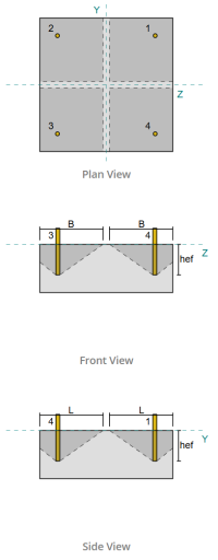
Dai un'occhiata #4: Calcola la capacità di breakout del calcestruzzo in tensione
Prima di calcolare la capacità di breakout, dobbiamo prima determinare se il membro si qualifica come a membro stretto. Secondo CSA A23.3:19 Clausola D.6.2.3, Il membro non soddisfa i criteri per un membro ristretto. Pertanto, il dato Efficace lunghezza dell'incorporamento verrà utilizzato nei calcoli.
Usando CSA A23.3:19 Eq. D.5, calcoliamo il Area di cono in cemento massimo previsto per un'unica ancora, in base alla lunghezza efficace dell'incorporamento.
\(
UN_{Ricorda} = 9 (h_{ef,Sforzo in alto Rinforzo})^2 = 9 \volte (130 \, \testo{mm})^2 = 152100 \, \testo{mm}^ 2
\)
Allo stesso modo, Usiamo la lunghezza effettiva di incorporamento per calcolare il Area di cono in cemento realizzato effettivo dell'ancoraggio singolo.
\(
UN_{Nc} = L_{Nc} B_{Nc} = 270 \, \testo{mm} \volte 270 \, \testo{mm} = 72900 \, \testo{mm}^ 2
\)
Dove,
\(
L_{Nc} = sinistra( \min a sinistra( c_{\testo{sinistra},Sforzo in alto Rinforzo}, 1.5 h_{ef,Sforzo in alto Rinforzo} \giusto) \giusto) + \sinistra( \min a sinistra( c_{\testo{giusto},Sforzo in alto Rinforzo}, 1.5 h_{ef,Sforzo in alto Rinforzo} \giusto) \giusto)
\)
\(
L_{Nc} = sinistra( \min a sinistra( 475 \, \testo{mm}, 1.5 \volte 130 \, \testo{mm} \giusto) \giusto) + \sinistra( \min a sinistra( 75 \, \testo{mm}, 1.5 \volte 130 \, \testo{mm} \giusto) \giusto)
\)
\(
L_{Nc} = 270 \, \testo{mm}
\)
\(
B_{Nc} = sinistra( \min a sinistra( c_{\testo{superiore},Sforzo in alto Rinforzo}, 1.5 h_{ef,Sforzo in alto Rinforzo} \giusto) \giusto) + \sinistra( \min a sinistra( c_{\testo{parte inferiore},Sforzo in alto Rinforzo}, 1.5 h_{ef,Sforzo in alto Rinforzo} \giusto) \giusto)
\)
\(
B_{Nc} = sinistra( \min a sinistra( 75 \, \testo{mm}, 1.5 \volte 130 \, \testo{mm} \giusto) \giusto) + \sinistra( \min a sinistra( 475 \, \testo{mm}, 1.5 \volte 130 \, \testo{mm} \giusto) \giusto)
\)
\(
B_{Nc} = 270 \, \testo{mm}
\)
Successivamente, Valutiamo il preso in considerazione Resistenza al breakout in cemento di base di un singolo ancoraggio usando CSA A23.3:19 Eq. D.6
\(
N_{br} = k_c phi lambda_a sqrt{\frac{f'_c}{\testo{MPa}}} \sinistra( \frac{h_{ef,Sforzo in alto Rinforzo}}{\testo{mm}} \giusto)^{1.5} R n
\)
\(
N_{br} = 10 \volte 0.65 \volte 1 \volte sqrt{\frac{20.68 \, \testo{MPa}}{1 \, \testo{MPa}}} \volte sinistra( \frac{130 \, \testo{mm}}{1 \, \testo{mm}} \giusto)^{1.5} \volte 1 \volte 0.001 \, \testo{kN} = 43.813 \, \testo{kN}
\)
Dove,
- \(Eurocodice di design con piastra di base in acciaio{c} = 10\) per ancore gettate
- \(\lambda = 1.0 \) per cemento normale
Adesso, Valutiamo gli effetti della geometria calcolando il Fattore di effetto Edge.
La distanza del bordo più breve del gruppo di ancoraggio è determinata come:
\(
c_{un carico,\testo{min}} = min sinistra( c_{\testo{sinistra},Sforzo in alto Rinforzo}, c_{\testo{giusto},Sforzo in alto Rinforzo}, c_{\testo{superiore},Sforzo in alto Rinforzo}, c_{\testo{parte inferiore},Sforzo in alto Rinforzo} \giusto) = min sinistra( 475 \, \testo{mm}, 75 \, \testo{mm}, 75 \, \testo{mm}, 475 \, \testo{mm} \giusto) = 75 \, \testo{mm}
\)
Secondo CSA A23.3:19 Eq. D.10 e D.11, il breakout Fattore di effetto Edge è:
\(
\Psi_{ed,N} = min sinistra( 1.0, 0.7 + 0.3 \sinistra( \frac{c_{un carico,\testo{min}}}{1.5 h_{ef,Sforzo in alto Rinforzo}} \giusto) \giusto) = min sinistra( 1, 0.7 + 0.3 \volte sinistra( \frac{75 \, \testo{mm}}{1.5 \volte 130 \, \testo{mm}} \giusto) \giusto) = 0.81538
\)
Inoltre, entrambi i fattore di cracking che per il fattore di divisione sono presi come:
\(
\Psi_{c,N} = 1
\)
\(
\Psi_{cp,N} = 1
\)
Poi, Combiniamo tutti questi fattori e utilizziamo ACI 318-19 Eq. 17.6.2.1b per valutare il preso in considerazione Resistenza a breakout in cemento dell'ancoraggio singolo:
\(
N_{cbr} = sinistra( \frac{UN_{Nc}}{UN_{Ricorda}} \giusto) \Psi_{ed,N} \Psi_{c,N} \Psi_{cp,N} N_{br} = sinistra( \frac{72900 \, \testo{mm}^ 2}{152100 \, \testo{mm}^ 2} \giusto) \volte 0.81538 \volte 1 \volte 1 \volte 43.813 \, \testo{kN} = 17.122 \, \testo{kN}
\)
Ricorda il precedentemente calcolato carico di tensione per ancoraggio:
\(
N_{fa} = frac{N_x}{N_{un carico,S}} = frac{50 \, \testo{kN}}{4} = 12.5 \, \testo{kN}
\)
Da 12.5 kN < 17.122 kN La capacità di breakout in cemento è sufficiente.
Questo calcolo di breakout in calcestruzzo si basa su ID ancoraggio #1. La stessa capacità si applicherà agli altri ancoraggi a causa del design simmetrico.
Dai un'occhiata #5: Calcola la capacità di estrazione dell'ancoraggio
La capacità di estrazione di un'ancora è governata dalla resistenza alla sua estremità incorporata. Per ancore agganciate, dipende dalla sua lunghezza del gancio.
Calcoliamo il Resistenza al pullut di base di base faticato per CSA A23.3:19 Eq. D.17.
\(
N_{Pr} = Psi_{c,p} 0.9 \phi (f'_c) e_h d_a r = 1 \volte 0.9 \volte 0.65 \volte (20.68 \, \testo{MPa}) \volte 60 \, \testo{mm} \volte 19.05 \, \testo{mm} \volte 1 = 13.828 \, \testo{kN}
\)
Ricorda il precedentemente calcolato carico di tensione per ancoraggio:
\(
N_{fa} = frac{N_x}{N_{un carico,t}} = frac{50 \, \testo{kN}}{4} = 12.5 \, \testo{kN}
\)
Da 12.5 kN < 13.828 kN, La capacità di estrazione dell'ancora è sufficiente.
Dai un'occhiata #6: Calcola la capacità di scoppio della faccia laterale nella direzione Y
Questo calcolo non è applicabile per le ancore allettate.
Dai un'occhiata #7: Calcola la capacità di scoppio della faccia laterale nella direzione z
Questo calcolo non è applicabile per le ancore allettate.
Riepilogo del progetto
La Software di progettazione della piastra di base Skyciv Può generare automaticamente un rapporto di calcolo passo-passo per questo esempio di progettazione. Fornisce inoltre un riepilogo dei controlli eseguiti e dei loro rapporti risultanti, rendere le informazioni facili da capire a colpo d'occhio. Di seguito è riportata una tabella di riepilogo del campione, che è incluso nel rapporto.
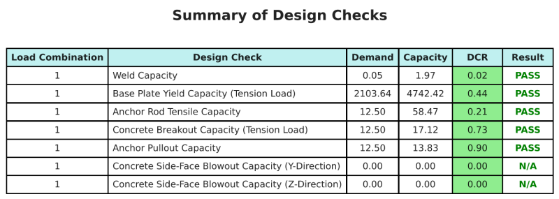
Rapporto campione Skyciv
Scopri il livello di dettaglio e chiarezza che puoi aspettarti da un rapporto sulla progettazione della piastra base SkyCiv. Il rapporto include tutti i controlli chiave della progettazione, equazioni, e i risultati presentati in un formato chiaro e di facile lettura. È pienamente conforme agli standard di progettazione. Fare clic di seguito per visualizzare un rapporto di esempio generato utilizzando il calcolatore della piastra di base SkyCiv.
Acquista software di base
Acquista la versione completa del modulo di progettazione della piastra di base Onits senza altri moduli SkyCiv. Questo ti dà un set completo di risultati per la progettazione della piastra di base, tra cui report dettagliati e più funzionalità.