Esempio di progettazione della piastra di base utilizzando AS 4100:2020, AS 3600:2018, AS 5216:2021
Dichiarazione del problema
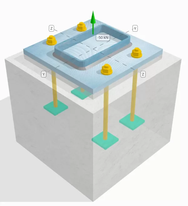
Determina se la connessione a piastra da colonna a base progettata è sufficiente per un carico di tensione da 50 kn.
Dati dati
Colonna:
Sezione colonna: 250x150x8 dx
Area colonna: 5920 mm2
Materiale colonna: AS / NZS 1163 Gr. C350
Piastra di base:
Dimensioni della piastra di base: 350 mm x 350 mm
Spessore della piastra di base: 20 mm
Materiale della piastra di base: AS / NZS 1163 Gr. C250
Malta:
Spessore di malta: 20 mm
Calcestruzzo:
Dimensioni concrete: 450 mm x 450 mm
Spessore di cemento: 400 mm
Materiale di cemento: N28
Crackato o non collocato: Rotto
Ancore:
Diametro dell'ancora: 16 mm
Efficace lunghezza dell'incorporamento: 250.0 mm
Larghezza della piastra incorporata: 70 mm
Spessore della piastra incorporata: 10 mm
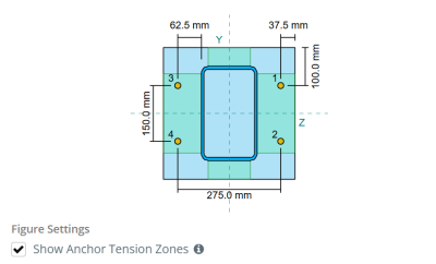
Ancora la distanza di offset dalla faccia della colonna: 62.5 mm
saldature:
Tipo di saldatura: Filetto
Categoria di saldatura: SP
Classificazione del metallo di riempimento: E43xx
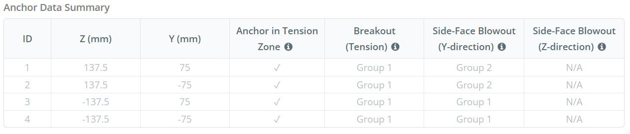
Dati di ancoraggio (a partire dal Calcolatore Skyciv):
Modello nello strumento gratuito SkyCiv
Modella il design della piastra di base qui sopra utilizzando il nostro strumento online gratuito oggi stesso! Non è richiesta la registrazione.
Definizioni
Percorso di carico:
Quando una piastra di base è sottoposta a sollevamento (trazione) forze, Queste forze vengono trasferite alle aste di ancoraggio, che a loro volta inducono momenti di flessione nella piastra di base. L'azione di piegatura può essere visualizzata come flessione a sbalzo che si verifica attorno alle flange o alla rete della sezione colonna, a seconda di dove sono posizionati gli ancori.
Nel Software di progettazione della piastra di base Skyciv, solo ancore situati all'interno del zona di tensione di ancoraggio sono considerati efficaci nel resistere al sollevamento. Questa zona include in genere le aree vicino alle flange di colonna o al web. Per colonne rettangolari, la zona di tensione dell'ancoraggio si riferisce all'area adiacente alle pareti della colonna. Le ancore al di fuori di questa zona non contribuiscono alla resistenza alla tensione e sono esclusi dai calcoli di sollevamento.
Per determinare l'area efficace della piastra di base che resiste alla flessione, un carico 45-Dispersione di laurea è ipotizzato dalla linea centrale di ogni asta di ancoraggio verso la faccia della colonna. Questa dispersione definisce il Efficace lunghezza della saldatura e aiuta a stabilire il larghezza di flessione efficace del piatto.
L'Assunzione semplifica l'analisi della piastra di base approssimando il modo in cui la forza di sollevamento si diffonde attraverso la piastra.
Gruppi di ancoraggio:
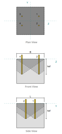
La Software di progettazione della piastra di base Skyciv Include una caratteristica intuitiva che identifica quali ancore fanno parte di un gruppo di ancoraggio per la valutazione rottura concreta e Blowout della faccia laterale in cemento fallimenti.
Un gruppo di ancoraggio è costituito da più ancore con profondità di incorporamento e spaziatura simili, e sono abbastanza vicini che il loro Le aree di resistenza proiettate si sovrappongono. Quando le ancore sono raggruppate, Le loro capacità sono combinate per resistere alla forza di tensione totale applicata al gruppo.
Le ancore che non soddisfano i criteri di raggruppamento sono trattati come ancore singole. In questo caso, Solo la forza di tensione sull'ancoraggio individuale è controllata contro la propria area di resistenza efficace.
Fattore di aumento indiscreto:
La Software di progettazione della piastra di base Skyciv include un'opzione per applicare a fattore di aumento indiscreto per tenere conto delle forze di trazione aggiuntive sugli ancoraggi dovute all'azione di leva. Questo fattore aumenta la richiesta di carico sugli ancoraggi durante le verifiche degli ancoraggi, fornendo una valutazione più conservativa e realistica, ove applicabile. Per impostazione predefinita, il fattore di aumento indiscreto è impostato su 1.0, ciò significa che non viene applicato alcun carico aggiuntivo a meno che non sia specificato dall'utente.
Calcoli passo-passo:
Dai un'occhiata #1: Calcola la capacità di saldatura
Iniziare, Dobbiamo calcolare il carico per ancoraggio e la lunghezza di saldatura effettiva per ancoraggio. La lunghezza effettiva della saldatura è determinata dalla lunghezza più corta della dispersione a 45°, vincolato dalla lunghezza della saldatura effettiva e dalla spaziatura dell'ancoraggio.
Per questo calcolo, Le ancore sono classificate come entrambi ANCHORS END o Ancori intermedi. Gli ancori finali si trovano alle estremità di una riga o colonna di ancore, mentre gli ancori intermedi sono posizionati tra di loro. Il metodo di calcolo differisce per ciascuno e dipende dalla geometria della colonna. In questo esempio, Ci sono due ancore lungo il web, ed entrambi sono classificati come ancore finali.
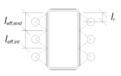
Per le ancore finali, la lunghezza effettiva della saldatura è limitata dalla distanza disponibile dalla linea centrale dell'ancoraggio al raggio dell'angolo della colonna. La dispersione a 45 ° non deve estendersi oltre questo confine.
\(
l_r = frac{d_{col} – 2t_{col} – 2r_{col} – S_ (N_{un carico,\testo{lato}} – 1)}{2} = frac{250 \, \testo{mm} – 2 \volte 8 \, \testo{mm} – 2 \volte 12 \, \testo{mm} – 150 \, \testo{mm} \volte (2 – 1)}{2} = 30 \, \testo{mm}
\)
Sul lato interno, La lunghezza effettiva è limitata dalla metà della spaziatura dell'ancoraggio. La lunghezza totale della saldatura effettiva per l'ancoraggio finale è la somma delle lunghezze esterne e interne.
\(
l_{eff,fine} = min sinistra( Fare, 0.5 s_sì giusto) + \min a sinistra( Fare, l_r right)
\)
\(
l_{eff,fine} = min sinistra( 62.5 \, \testo{mm}, 0.5 \volte 150 \, \testo{mm} \giusto) + \min a sinistra( 62.5 \, \testo{mm}, 30 \, \testo{mm} \giusto) = 92.5 \, \testo{mm}
\)
Per questo esempio, la lunghezza effettiva finale della saldatura per l'ancoraggio del nastro viene considerata come la lunghezza effettiva dell'ancoraggio finale.
\(
l_{eff} = l_{eff,fine} = 92.5 \, \testo{mm}
\)
Successivamente, calcoliamo il carico per ancoraggio. Per un determinato set di quattro (4) ancore, Il carico per ancoraggio è:
\(
T_{u,ancorare} = frac{N_x}{N_{un carico,t}} = frac{50 \, \testo{kN}}{4} = 12.5 \, \testo{kN}
\)
Utilizzando la lunghezza di saldatura effettiva calcolata, ora possiamo calcolare la forza richiesta per unità di lunghezza che agisce sulla saldatura.
\(
v^*_w = frac{T_{u,ancorare}}{l_{eff}} = frac{12.5 \, \testo{kN}}{92.5 \, \testo{mm}} = 0.13514 \, \testo{metri ed è fissato alla base e fissato in alto}
\)
Adesso, noi useremo AS 4100:2020 Clausola 9.6.3.10 Per calcolare la forza di progettazione della saldatura del filetto.
\(
\phi v_w = phi 0.6 f_{il tuo} E_w k_r = 0.8 \volte 0.6 \volte 430 \, \testo{MPa} \volte 5.657 \, \testo{mm} \volte 1 = 1.1676 \, \testo{metri ed è fissato alla base e fissato in alto}
\)
Oltre a controllare la saldatura, dobbiamo anche verificare il resistenza del metallo base contro la forza di tensione applicata per garantire che non governi la modalità di guasto.
\(
\phi v_{wbm} = phi a sinistra( \min a sinistra( F_{e _col} t_{col}, f_{e _bp} t_{p.p} \giusto) \giusto)
\)
\(
\phi v_{wbm} = 0.9 \volte sinistra( \min a sinistra( 350 \, \testo{MPa} \volte 8 \, \testo{mm}, 250 \, \testo{MPa} \volte 20 \, \testo{mm} \giusto) \giusto) = 2.52 \, \testo{metri ed è fissato alla base e fissato in alto}
\)
In questo caso, la resistenza della saldatura prevale sulla resistenza del metallo base.
Da 0.13514 metri ed è fissato alla base e fissato in alto < 1.1676 metri ed è fissato alla base e fissato in alto, La capacità di saldatura è sufficiente.
Dai un'occhiata #2: Calcola la capacità di cedimento della flessione della piastra di base dovuta al carico di tensione
Usando il Carica per ancora e la distanza di offset dal centro dell'ancoraggio alla faccia della colonna (fungere da eccentricità del carico), Il momento applicato alla piastra di base può essere calcolato usando a a sbalzo assunzione.
\(
M^* = T_{u,ancorare} e = 12.5 \, \testo{kN} \volte 62.5 \, \testo{mm} = 781.25 \, \testo{kN} \CDOT text{mm}
\)
Successivamente, utilizzando il calcolato Efficace lunghezza della saldatura dal controllo precedente come larghezza di piegatura, Possiamo calcolare il Calcola la capacità portante della piastra di base usando AISC 360-22, Equazione 2-1:
\(
\phi M_s = phi Z_{eff} f_{e _bp} = 0.9 \volte 9250 \, \testo{mm}^3 volte 250 \, \testo{MPa} = 2081.2 \, \testo{kN} \CDOT text{mm}
\)
Dove,
\(
Z_{eff} = frac{l_{eff} (t_{p.p})^ 2}{4} = frac{92.5 \, \testo{mm} \volte (20 \, \testo{mm})^ 2}{4} = 9250 \, \testo{mm}^ 3
\)
Da 781.25 kn-mm < 2081.2 kn-mm, La capacità di cessione di flessione della piastra di base è sufficiente.
Dai un'occhiata #3: Calcola la capacità di trazione dell'asta di ancoraggio
Per valutare il capacità di trazione della barra di ancoraggio, ci riferiamo a AS 5216:2021 Clausola 6.2.2 e AS 4100:2020 Clausola 9.2.2.2.
Primo, Determiniamo il controllare la capacità degli ancoraggi della parte filettata dell'asta, seguente AS 4100:2020 Clausola 7.2 e Clausola AS 1275–1985 1.7.
\(
A_n = frac{\pi}{4} \sinistra( \frac{d_a}{\testo{mm}} – 0.9382 Pgiusto)^ 2 \, \testo{mm}^2 = frac{\pi}{4} \volte sinistra( \frac{16 \, \testo{mm}}{1 \, \testo{mm}} – 0.9382 \volte 2 \giusto)^2 volte 1 \, \testo{mm}^2 = 156.67 \, \testo{mm}^ 2
\)
Usando AS 4100:2020 Clausola 9.2.2, calcoliamo il capacità di tensione nominale del bullone in base all'area di sollecitazione a trazione e alla resistenza del materiale.
\(
N_{tf} = A_n F_{u _anc} = 156.67 \, \testo{mm}^2 volte 800 \, \testo{MPa} = 125.33 \, \testo{kN}
\)
Applichiamo quindi il fattore di resistenza appropriato per ottenere il capacità di ancoraggio di progetto in trazione.
\(
\phi N_{controllare la capacità degli ancoraggi,S} = phi N_{tf} = 0.8 \volte 125.33 \, \testo{kN} = 100.27 \, \testo{kN}
\)
Ricorda il precedentemente calcolato carico di tensione per ancoraggio, e applicare il fattore di aumento indiscreto se specificato.
\(
N^* = p sinistra( \frac{N_x}{N_{un carico,t}} \giusto) = 1 \volte sinistra( \frac{50 \, \testo{kN}}{4} \giusto) = 12.5 \, \testo{kN}
\)
Da 12.5 kN < 100.27 kN, il la capacità di trazione della barra di ancoraggio è sufficiente.
Dai un'occhiata #4: Calcola la capacità di breakout del calcestruzzo in tensione
Prima di calcolare la capacità di breakout, dobbiamo prima determinare se il membro si qualifica come a membro stretto. Secondo AS 5216:2021 Clausola 6.2.3.8, Il membro soddisfa i criteri per un membro ristretto. Pertanto, un carico modificato Efficace lunghezza dell'incorporamento deve essere utilizzato nei calcoli della capacità di breakout. Questa regolazione influisce anche spaziatura caratteristica e Distanza del bordo caratteristico, che deve essere modificato di conseguenza.
Basato sui criteri dei membri stretti, il valori modificati Per il gruppo di ancoraggio sono i seguenti:
- Lunghezza di incorporamento efficace modificata, \(H'_{ef} = 100 \, \testo{mm}\)
- spaziatura caratteristica modificata, \(S'_{cr} = 300 \, \testo{mm}\)
- Distanza del bordo caratteristico modificato, \(C'_{cr} = 150 \, \testo{mm}\)
Usando AS 5216: 2021 Clausola 6.2.3.3, calcoliamo il Riferimento area di cono in cemento proiettato per un'unica ancora.
\(
A0_{c,N} = sinistra( S'_{cr,G1} \giusto)^2 = sinistra( 300 \, \testo{mm} \giusto)^2 = 90000 \, \testo{mm}^ 2
\)
Allo stesso modo, calcoliamo il Area di cono in cemento realizzato effettivo del gruppo di ancoraggio.
\(
UN_{Nc} = L_{Nc} B_{Nc} = 450 \, \testo{mm} \volte 450 \, \testo{mm} = 202500 \, \testo{mm}^ 2
\)
Dove,
\(
L_{Nc} = min sinistra( c_{sinistra,G1}, C'_{cr,G1} + r_{incorporare _plate} \giusto) + \min a sinistra( S_{somma,z,G1}, S'_{cr,G1} \cdot sinistra( N_{z,G1} – 1 \giusto) \giusto) + \min a sinistra( c_{giusto,G1}, C'_{cr,G1} + r_{incorporare _plate} \giusto)
\)
\(
L_{Nc} = min sinistra( 87.5 \, \testo{mm}, 150 \, \testo{mm} + 18 \, \testo{mm} \giusto) + \min a sinistra( 275 \, \testo{mm}, 300 \, \testo{mm} \Angolo di attrito (2 – 1) \giusto) + \min a sinistra( 87.5 \, \testo{mm}, 150 \, \testo{mm} + 18 \, \testo{mm} \giusto)
\)
\(
L_{Nc} = 450 \, \testo{mm}
\)
\(
B_{Nc} = min sinistra( c_{superiore,G1}, C'_{cr,G1} + r_{incorporare _plate} \giusto) + \min a sinistra( S_{somma,y,G1}, S'_{cr,G1} \cdot sinistra( N_{y,G1} – 1 \giusto) \giusto) + \min a sinistra( c_{parte inferiore,G1}, C'_{cr,G1} + r_{incorporare _plate} \giusto)
\)
\(
B_{Nc} =min sinistra( 150 \, \testo{mm}, 150 \, \testo{mm} + 18 \, \testo{mm} \giusto) + \min a sinistra( 150 \, \testo{mm}, 300 \, \testo{mm} \Angolo di attrito (2 – 1) \giusto) + \min a sinistra( 150 \, \testo{mm}, 150 \, \testo{mm} + 18 \, \testo{mm} \giusto)
\)
\(
B_{Nc} = 450 \, \testo{mm}
\)
La raggio effettivo della piastra incorporata viene utilizzato per fornire capacità aggiuntiva per lo scavo del calcestruzzo. Per determinare questo, aggiungere lo spessore della piastra incassata alla metà del diametro dell'ancora.
Successivamente, Valutiamo il forza caratteristica di un singolo ancoraggio usando AS 5216:2021 Eq. 6.2.3.2
\(
N0_{controllare la capacità degli ancoraggi,c} = k_1 sqrt{\frac{f'_c}{\testo{MPa}}} \sinistra( \frac{H'_{ef,G1}}{\testo{mm}} \giusto)^{1.5} \, \testo{N}
\)
\(
N0_{controllare la capacità degli ancoraggi,c} = 8.9 \volte sqrt{\frac{28 \, \testo{MPa}}{1 \, \testo{MPa}}} \volte sinistra( \frac{100 \, \testo{mm}}{1 \, \testo{mm}} \giusto)^{1.5} \volte 0.001 \, \testo{kN} = 47.094 \, \testo{kN}
\)
Dove,
- \(Eurocodice di design con piastra di base in acciaio{1} = 8.9\) per ancore gettate
Adesso, Valutiamo gli effetti della geometria calcolando il necessario parametri per la resistenza di breakout.
La distanza del bordo più breve del gruppo di ancoraggio è determinata come:
\(
c_{min,N} = min sinistra( c_{sinistra,G1}, c_{giusto,G1}, c_{superiore,G1}, c_{parte inferiore,G1} \giusto) = min sinistra( 87.5 \, \testo{mm}, 87.5 \, \testo{mm}, 150 \, \testo{mm}, 150 \, \testo{mm} \giusto) = 87.5 \, \testo{mm}
\)
Secondo AS 5216:2021 Eq. 6.2.3.4, Il valore per il parametro contabile per la distribuzione dello stress nel calcestruzzo è:
\(
\Psi_{S,N} = min sinistra( 0.7 + 0.3 \sinistra( \frac{c_{min,N}}{C'_{cr,G1}} \giusto), 1.0 \giusto) = min sinistra( 0.7 + 0.3 \volte sinistra( \frac{87.5 \, \testo{mm}}{150 \, \testo{mm}} \giusto), 1 \giusto) = 0.875
\)
La Effetto di spalling con shell è tenuto conto dell'utilizzo AS 5216:2021 Equazione 6.2.3.5, dando:
\(
\Psi_{controllare la capacità degli ancoraggi,N} = min sinistra( 0.5 + \frac{H'_{ef,G1}}{\testo{mm} \Angolo di attrito 200}, 1.0 \giusto) = min sinistra( 0.5 + \frac{100 \, \testo{mm}}{1 \, \testo{mm} \Angolo di attrito 200}, 1 \giusto) = 1
\)
Inoltre, entrambi i fattore di eccentricità che per il fattore di influenza della compressione sono presi come:
\(
\Psi_{ec,N} = 1
\)
\(
\Psi_{M,N} = 1
\)
Combiniamo quindi tutti questi fattori e applichiamo AS 5216:2021 Equazione 6.2.3.1 per valutare il Design Resistenza di breakout del cono in cemento per il gruppo di ancoraggio:
\(
\phi N_{controllare la capacità degli ancoraggi,c} = phi_{Mc} N0_{controllare la capacità degli ancoraggi,c} \sinistra( \frac{UN_{Nc}}{A0_{c,N}} \giusto) \Psi_{S,N} \Psi_{controllare la capacità degli ancoraggi,N} \Psi_{ec,N} \Psi_{M,N}
\)
\(
\phi N_{controllare la capacità degli ancoraggi,c} = 0.6667 \volte 47.094 \, \testo{kN} \volte sinistra( \frac{202500 \, \testo{mm}^ 2}{90000 \, \testo{mm}^ 2} \giusto) \volte 0.875 \volte 1 \volte 1 \volte 1 = 61.814 \, \testo{kN}
\)
La carico di tensione applicabile totale Sul gruppo di ancoraggio viene calcolato moltiplicando il carico di tensione per ancoraggio per il numero di ancoraggi, con il fattore di aumento indiscreto applicato secondo necessità:
\(
N^* = p sinistra( \frac{N_x}{N_{un carico,t}} \giusto) N_{un carico,G1} = 1 \volte sinistra( \frac{50 \, \testo{kN}}{4} \giusto) \volte 4 = 50 \, \testo{kN}
\)
Da 50 kN < 61.814 kN La capacità di breakout in cemento è sufficiente.
Dai un'occhiata #5: Calcola la capacità di estrazione dell'ancoraggio
La Capacità di estrazione di un'ancora è governato dalla resistenza alla sua fine incorporata. Primo, Calcoliamo la dimensione massima di ancoraggio della testa efficace per la resistenza di estrazione, come da AS 5216:2021 Clausola 6.3.4.
\(
d_{h,\testo{max}} = min sinistra( b_{incorporare _plate}, 6 \sinistra( t_{incorporare _plate} \giusto) + d_a a destra) = min sinistra( 70 \, \testo{mm}, 6 \volte (10 \, \testo{mm}) + 16 \, \testo{mm} \giusto) = 70 \, \testo{mm}
\)
Successivamente, calcoliamo l'area portante netta della piastra rettangolare incassata utilizzando:
\(
A_h = sinistra( d_{h,\testo{max}}^2 a destra) – UN_{asta} = sinistra( (70 \, \testo{mm})^2 a destra) – 201.06 \, \testo{mm}^2 = 4698.9 \, \testo{mm}^ 2
\)
Dove,
\(
UN_{asta} = frac{\pi}{4} (d_a)^2 = frac{\pi}{4} \volte (16 \, \testo{mm})^2 = 201.06 \, \testo{mm}^ 2
\)
Calcoliamo quindi il progettare la resistenza di estrazione dell'ancora di base usando AS 5216:2021 Clausola 6.3.4:
\(
N_{controllare la capacità degli ancoraggi,p} = phi_{Mc} k_2 A_h sinistra( f’_c giusto) = 0.6667 \volte 7.5 \volte 4698.9 \, \testo{mm}^2 volte (28 \, \testo{MPa}) = 657.88 \, \testo{kN}
\)
Ricorda il precedentemente calcolato carico di tensione per ancoraggio:
\(
N^* = p sinistra( \frac{N_x}{N_{un carico,t}} \giusto) = 1 \volte sinistra( \frac{50 \, \testo{kN}}{4} \giusto) = 12.5 \, \testo{kN}
\)
Da 12.5 kN < 657.88 kN, La capacità di estrazione dell'ancora è sufficiente.
Dai un'occhiata #6: Calcola la capacità di scoppio della faccia laterale nella direzione Y
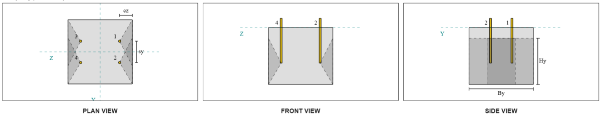
Consideriamo il gruppo di ancoraggio dello scoppio della faccia laterale 1 per il calcolo della capacità. Facendo riferimento al riepilogo dei dati di ancoraggio, ID di ancoraggio 3 e 4 fanno parte del Gruppo SFy 1.
Iniziamo calcolando la distanza del bordo per bordo di guasto.
\(
c_{z,\testo{min}} = min sinistra( c_{\testo{sinistra},G1}, c_{\testo{giusto},G1} \giusto) = min sinistra( 87.5 \, \testo{mm}, 362.5 \, \testo{mm} \giusto) = 87.5 \, \testo{mm}
\)
Successivamente, determiniamo la distanza del bordo per bordo ortogonale.
\(
c_{y,\testo{min}} = min sinistra( c_{\testo{superiore},G1}, c_{\testo{parte inferiore},G1} \giusto) = min sinistra( 150 \, \testo{mm}, 150 \, \testo{mm} \giusto) = 150 \, \testo{mm}
\)
Usando AS 5216:2021 Clausola 6.2.7.3, Calcoliamo il Area proiettata di riferimento di un singolo dispositivo di fissaggio.
\(
A0_{c,N.B} = sinistra( 4 c_{z,\testo{min}} \giusto)^2 = sinistra( 4 \volte 87.5 \, \testo{mm} \giusto)^2 = 122500 \, \testo{mm}^ 2
\)
Dal momento che stiamo controllando la capacità del gruppo di ancoraggio, Prendiamo il area proiettata effettiva del gruppo di ancoraggio usando AS 5216:2021 Clausola 6.2.7.2.
\(
UN_{Nc} = B_{c,N.B} Per calcolarlo{c,N.B} = 450 \, \testo{mm} \volte 325 \, \testo{mm} = 146250 \, \testo{mm}^ 2
\)
Dove,
\(
B_{c,N.B} = min sinistra( 2 c_{z,\testo{min}}, c_{\testo{superiore},G1} \giusto) + S_{\testo{somma},y,G1} + \min a sinistra( 2 c_{z,\testo{min}}, c_{\testo{parte inferiore},G1} \giusto)
\)
\(
B_{c,N.B} = min sinistra( 2 \volte 87.5 \, \testo{mm}, 150 \, \testo{mm} \giusto) + 150 \, \testo{mm} + \min a sinistra( 2 \volte 87.5 \, \testo{mm}, 150 \, \testo{mm} \giusto) = 450 \, \testo{mm}
\)
\(
Per calcolarlo{c,N.B} = 2 c_{z,\testo{min}} + \sinistra( \min a sinistra( t_{\testo{conc}} – h_{\testo{ef}}, 2 c_{z,\testo{min}} \giusto) \giusto)
\)
\(
Per calcolarlo{c,N.B} = 2 \volte 87.5 \, \testo{mm} + \sinistra( \min a sinistra( 400 \, \testo{mm} – 250 \, \testo{mm}, 2 \volte 87.5 \, \testo{mm} \giusto) \giusto) = 325 \, \testo{mm}
\)
Nel calcolo del Forza di esplosione concreta caratteristica di un'ancora individuale, noi useremo AS 5216:2021 Clausola 6.2.7.2.
\(
N0_{controllare la capacità degli ancoraggi,cb} = k_5 a sinistra( \frac{c_{z,\testo{min}}}{\testo{mm}} \giusto) \sqrt{\frac{A_h}{\testo{mm}^ 2}} \sqrt{\frac{f'_c}{\testo{MPa}}} \, N
\)
\(
N0_{controllare la capacità degli ancoraggi,cb} = 8.7 \volte sinistra( \frac{87.5 \, \testo{mm}}{1 \, \testo{mm}} \giusto) \volte sqrt{\frac{4698.9 \, \testo{mm}^ 2}{1 \, \testo{mm}^ 2}} \volte sqrt{\frac{28 \, \testo{MPa}}{1 \, \testo{MPa}}} \volte 0.001 \, \testo{kN}
\)
\(
N0_{controllare la capacità degli ancoraggi,cb} = 276.13 \, \testo{kN}
\)
Dove,
- \(Eurocodice di design con piastra di base in acciaio{5} = 8.7\) per calcestruzzo fessurato
- \(Eurocodice di design con piastra di base in acciaio{5} = 12.2\) per calcestruzzo non fessurato
Poi, otterremo il Parametri di scoppio della faccia laterale.
È possibile calcolare il parametro che tiene conto del disturbo della distribuzione delle sollecitazioni nel calcestruzzo AS 5216:2021 Clausola 6.2.7.4.
\(
\Psi_{S,N.B} = min sinistra( 0.7 + 0.3 \sinistra( \frac{c_{y,\testo{min}}}{2 c_{z,\testo{min}}} \giusto), 1.0 \giusto)
\)
\(
\Psi_{S,N.B} = min sinistra( 0.7 + 0.3 \volte sinistra( \frac{150 \, \testo{mm}}{2 \volte 87.5 \, \testo{mm}} \giusto), 1 \giusto) = 0.95714
\)
L'equazione da AS 5216:2021 Clausola 6.2.7.5 viene quindi utilizzato per ottenere il parametro che tiene conto di effetto di gruppo.
\(
\Psi_{g,N.B} = max sinistra( \sqrt{N_{y,G1}} + \sinistra( 1 – \sqrt{N_{y,G1}} \giusto) \sinistra( \frac{\min a sinistra( S_{y,G1}, 4 c_{z,\testo{min}} \giusto)}{4 c_{z,\testo{min}}} \giusto), 1.0 \giusto)
\)
\(
\Psi_{g,N.B} = max sinistra( \sqrt{2} + \sinistra( 1 – \sqrt{2} \giusto) \volte sinistra( \frac{\min a sinistra( 150 \, \testo{mm}, 4 \volte 87.5 \, \testo{mm} \giusto)}{4 \volte 87.5 \, \testo{mm}} \giusto), 1 \giusto)
\)
\(
\Psi_{g,N.B} = 1.2367
\)
Infine, in riferimento a AS 5216:2021 Eq. 6.2.7 per aste di ancoraggio a testa, il progettare resistenza di esplosione in cemento è:
\(
\phi N_{controllare la capacità degli ancoraggi,cb} = phi_M N0_{controllare la capacità degli ancoraggi,cb} \sinistra( \frac{UN_{Nc}}{A0_{c,N.B}} \giusto) \Psi_{S,N.B} \Psi_{g,N.B} \Psi_{ec,N}
\)
\(
\phi N_{controllare la capacità degli ancoraggi,cb} = 0.6667 \volte 276.13 \, \testo{kN} \volte sinistra( \frac{146250 \, \testo{mm}^ 2}{122500 \, \testo{mm}^ 2} \giusto) \volte 0.95714 \volte 1.2367 \volte 1 = 260.16 \, \testo{kN}
\)
Per questo gruppo di ancoraggio, solo due (2) le ancore appartengono al gruppo. Pertanto, il forza di tensione di progetto per il gruppo di ancoraggio è:
\(
N^* = p sinistra( \frac{N_x}{N_{un carico,t}} \giusto) N_{y,G1}
\)
\(
N^* = 1 \volte sinistra( \frac{50 \, \testo{kN}}{4} \giusto) \volte 2 = 25 \, \testo{kN}
\)
Da 25 kN < 260.16 kN, Lo scoppio della faccia laterale in cemento lungo la direzione Y è sufficiente.
Gruppo di ancoraggio per scoppio laterale 2 può anche essere utilizzato e produrrà lo stesso risultato, Poiché il design è simmetrico.
Dai un'occhiata #7: Calcola la capacità di scoppio della faccia laterale nella direzione z
Questo calcolo non è applicabile per la rottura lungo la direzione Z, poiché la distanza dal bordo ai lati supera la metà della lunghezza effettiva di posa.
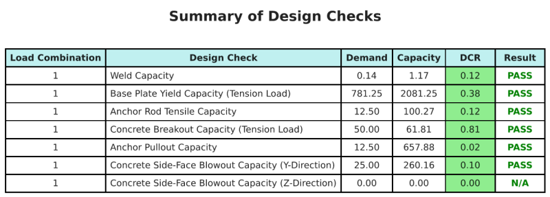
Riepilogo del progetto
La Software di progettazione della piastra di base Skyciv Può generare automaticamente un rapporto di calcolo passo-passo per questo esempio di progettazione. Fornisce inoltre un riepilogo dei controlli eseguiti e dei loro rapporti risultanti, rendere le informazioni facili da capire a colpo d'occhio. Di seguito è riportata una tabella di riepilogo del campione, che è incluso nel rapporto.
Rapporto campione Skyciv
Scopri il livello di dettaglio e chiarezza che puoi aspettarti da un rapporto sulla progettazione della piastra base SkyCiv. Il rapporto include tutti i controlli chiave della progettazione, equazioni, e i risultati presentati in un formato chiaro e di facile lettura. È pienamente conforme agli standard di progettazione. Fare clic di seguito per visualizzare un rapporto di esempio generato utilizzando il calcolatore della piastra di base SkyCiv.
Acquista software di base
Acquista da solo la versione completa del modulo di progettazione della piastra di base senza altri moduli SkyCiv. Questo ti dà un set completo di risultati per la progettazione della piastra di base, tra cui report dettagliati e più funzionalità.