Esempio di design della piastra di base utilizzando AISC 360-22 e ACI 318-19
Dichiarazione del problema
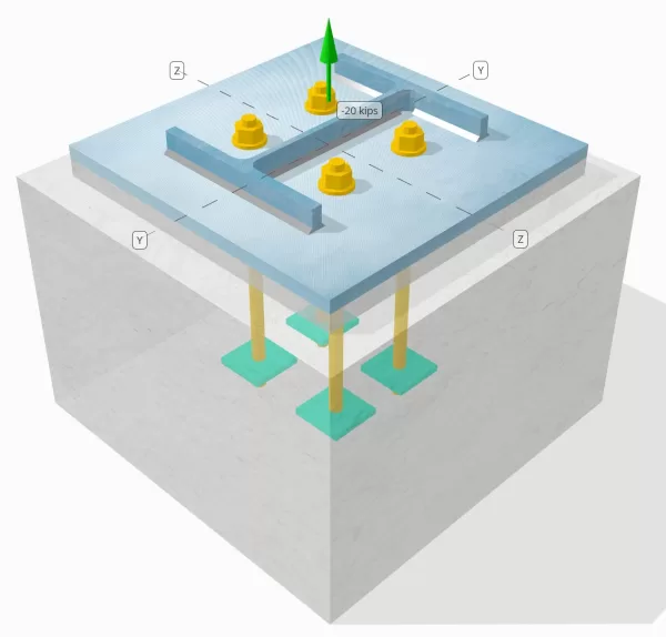
Determina se la connessione a piastra da colonna a base progettata è sufficiente per un carico di tensione di 20 kip.
Dati dati
Colonna:
Sezione colonna: W12X53
Area colonna: 15.6 pollici2
Materiale colonna: A992
Piastra di base:
Dimensioni della piastra di base: 18 in x 18 pollici
Spessore della piastra di base: 3/4 pollici
Materiale della piastra di base: A36
Malta:
Spessore di malta: 1 pollici
Calcestruzzo:
Dimensioni concrete: 22 in x 22 pollici
Spessore di cemento: 15 pollici
Materiale di cemento: 4000 psi
Crackato o non collocato: Rotto
Ancore:
Diametro dell'ancora: 3/4 pollici
Efficace lunghezza dell'incorporamento: 12 pollici
Larghezza della piastra incorporata: 3 pollici
Spessore della piastra incorporata: 1/4 pollici
Ancora la distanza di offset dalla faccia della colonna Web: 2.8275 pollici
saldature:
Dimensione della saldatura: 1/4 pollici
Classificazione del metallo di riempimento: E70XX
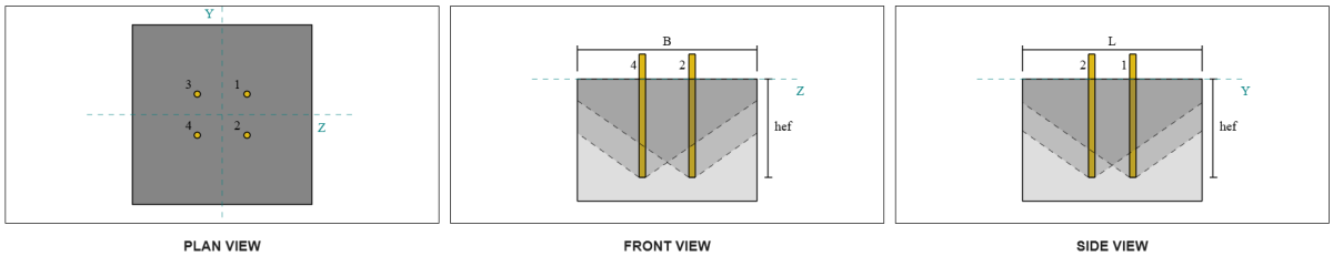
Dati di ancoraggio (a partire dal Calcolatore Skyciv):
Modello nello strumento gratuito SkyCiv
Modella il design della piastra di base qui sopra utilizzando il nostro strumento online gratuito oggi stesso! Non è richiesta la registrazione.
Definizioni
Percorso di carico:
Quando una piastra di base è sottoposta a sollevamento (trazione) forze, Queste forze vengono trasferite alle aste di ancoraggio, che a loro volta inducono momenti di flessione nella piastra di base. L'azione di piegatura può essere visualizzata come flessione a sbalzo che si verifica attorno alle flange o alla rete della sezione colonna, a seconda di dove sono posizionati gli ancori.
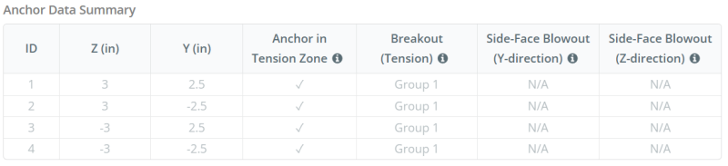
Nel Software di progettazione della piastra di base Skyciv, solo ancore situati all'interno del zona di tensione di ancoraggio sono considerati efficaci nel resistere al sollevamento. Questa zona include in genere le aree vicino alle flange di colonna o al web. Le ancore al di fuori di questa zona non contribuiscono alla resistenza alla tensione e sono esclusi dai calcoli di sollevamento.
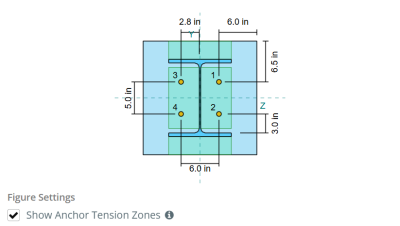
Per determinare l'area efficace della piastra di base che resiste alla flessione, un carico 45-Dispersione di laurea è ipotizzato dalla linea centrale di ogni asta di ancoraggio verso la faccia della colonna. Questa dispersione definisce il Efficace lunghezza della saldatura e aiuta a stabilire il larghezza di flessione efficace del piatto.
L'Assunzione semplifica l'analisi della piastra di base approssimando il modo in cui la forza di sollevamento si diffonde attraverso la piastra.
Gruppi di ancoraggio:
La Software di progettazione della piastra di base Skyciv Include una caratteristica intuitiva che identifica quali ancore fanno parte di un gruppo di ancoraggio per la valutazione rottura concreta e cemento sidE-Face Blowout fallimenti.
Un gruppo di ancoraggio è costituito da più ancore con profondità di incorporamento e spaziatura simili, e sono abbastanza vicini che il loro Le aree di resistenza proiettate si sovrappongono. Quando le ancore sono raggruppate, Le loro capacità sono combinate per resistere alla forza di tensione totale applicata al gruppo.
Le ancore che non soddisfano i criteri di raggruppamento sono trattati come ancore singole. In questo caso, Solo la forza di tensione sull'ancoraggio individuale è controllata contro la propria area di resistenza efficace.
Calcoli passo-passo
Dai un'occhiata #1: Calcola la capacità di saldatura
Iniziare, Dobbiamo calcolare il carico per ancoraggio e la lunghezza di saldatura effettiva per ancoraggio. La lunghezza di saldatura effettiva è determinata dalla lunghezza più breve da 45° dispersione, vincolato dalla lunghezza della saldatura effettiva e dalla spaziatura dell'ancoraggio.
Per questo calcolo, Le ancore sono classificate come entrambi ANCHORS END o Ancori intermedi. Gli ancori finali si trovano alle estremità di una riga o colonna di ancore, mentre gli ancori intermedi sono posizionati tra di loro. Il metodo di calcolo differisce per ciascuno e dipende dalla geometria della colonna. In questo esempio, Ci sono due ancore lungo il web, ed entrambi sono classificati come ancore finali.
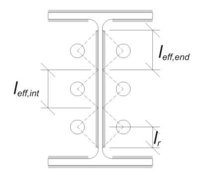
Per le ancore finali, La lunghezza di saldatura effettiva è limitata dalla distanza disponibile dalla linea centrale di ancoraggio al filetto della colonna. La dispersione a 45 ° non deve estendersi oltre questo confine.
\(
l_r = frac{d_{col} – 2t_f – 2r_{col} – S_(N_{un carico,lato} – 1)}{2} = frac{12.1 \, \testo{pollici} – 2 \volte 0.575 \, \testo{pollici} – 2 \volte 0.605 \, \testo{pollici} – 5 \, \testo{pollici} \volte (2 – 1)}{2} = 2.37 \, \testo{pollici}
\)
Sul lato interno, La lunghezza effettiva è limitata dalla metà della spaziatura dell'ancoraggio. La lunghezza totale della saldatura effettiva per l'ancoraggio finale è la somma delle lunghezze esterne e interne.
\(
l_{eff,fine} = min(Fare, 0.5S_) + \min(Fare, l_r)
\)
\(
l_{eff,fine} = min(2.8275 \, \testo{pollici}, 0.5 \volte 5 \, \testo{pollici}) + \min(2.8275 \, \testo{pollici}, 2.37 \, \testo{pollici}) = 4.87 \, \testo{pollici}
\)
Per questo esempio, il Lunghezza di saldatura efficace finale poiché l'ancoraggio web è considerata la lunghezza effettiva dell'ancoraggio finale.
\(
l_{eff} = l_{eff,fine} = 4.87 \, \testo{pollici}
\)
Successivamente, Calcoliamo il Carica per ancora. Per un determinato set di quattro (4) ancore, Il carico per ancoraggio è:
\(
T_{u,ancorare} = frac{N_x}{N_{un carico,t}} = frac{20 \, \testo{kip}}{4} = 5 \, \testo{kip}
\)
Utilizzando la lunghezza di saldatura effettiva calcolata, ora possiamo determinare il forza richiesta per unità di lunghezza sulla saldatura.
\(
r_u = frac{T_{u,ancorare}}{l_{eff}} = frac{5 \, \testo{kip}}{4.87 \, \testo{pollici}} = 1.0267 \, \testo{kip/in}
\)
Adesso, noi useremo AISC 360-22, CAPITOLO J2.4 Per calcolare la forza di progettazione della saldatura del filetto.
Poiché il carico applicato è una tensione puramente assiale, l'angolo \(\theta) è preso come 90 °, e il coefficiente di resistenza direzionale KDS viene calcolato secondo AISC 360-22 Eq. J2-5.
\(
Eurocodice di design con piastra di base in acciaio{ds} = 1.0 + 0.5(\senza(\theta))^{1.5} = 1 + 0.5 \volte (\senza(1.5708))^{1.5} = 1.5
\)
Infine, applicheremo AISC 360-22 Eq. J2-4 per determinare il Riducitura del design della saldatura del filetto per unità di lunghezza.
\(
\Phi r_n = phi 0.6 F_{Exx} E_{w,ragnatela} Eurocodice di design con piastra di base in acciaio{ds} = 0.75 \volte 0.6 \volte 70 \, \testo{KSI} \volte 0.177 \, \testo{pollici} \volte 1.5 = 8.3633 \, \testo{kip/in}
\)
Da 1.0267 KPI < 8.3633 KPI, La capacità di saldatura è sufficiente.
Dai un'occhiata #2: Calcola la capacità di cedimento della flessione della piastra di base dovuta al carico di tensione
Usando tCarica per ancora e il oDistanza FFSET dal centro dell'ancora alla faccia della colonna (fungere da eccentricità del carico), Il momento applicato alla piastra di base può essere calcolato usando a a sbalzo assunzione.
\(
M_u = t_{u,\testo{ancorare}} e = 5 \, \testo{kip} \volte 2.8275 \, \testo{pollici} = 14.137 \, \testo{kip} \CDOT text{pollici}
\)
Successivamente, usando il calcolod Lunghezza di saldatura efficace perm Il controllo precedente come larghezza di flessione, Possiamo calcolare il Calcola la capacità portante della piastra di base usando AISC 360-22, Equazione 2-1:
\(
\non -m_n = phi f_{y,\testo{p.p}} Z_{\testo{eff}} = 0.9 \volte 36 \, \testo{KSI} \volte 0.68484 \, \testo{pollici}^3 = 22.189 \, \testo{kip} \CDOT text{pollici}
\)
Dove,
\(
Z_{\testo{eff}} = frac{l_{\testo{eff}} (t_{\testo{p.p}})^ 2}{4} = frac{4.87 \, \testo{pollici} \volte (0.75 \, \testo{pollici})^ 2}{4} = 0.68484 \, \testo{pollici}^ 3
\)
Da 14.137 pollo-in < 22.189 pollo-in, La capacità di cessione di flessione della piastra di base è sufficiente.
Dai un'occhiata #3: Calcola la capacità di trazione dell'asta di ancoraggio
Per valutare la capacità di trazione dell'asta di ancoraggio, noi useremo ACI 318-19 Equazione 17.6.1.2.
Primo, Determiniamo il forza di trazione specificata dell'acciaio di ancoraggio. Questo è il valore più basso consentito da ACI 318-19 Clausola 17.6.1.2, con riferimento alle proprietà del materiale in AISC 360-22 Tabella J3.2.
\(
f_{\testo{uta}} = min sinistra( 0.75 F_{u,\testo{anc}}, 1.9 F_{y,\testo{anc}}, 125 \giusto) = min sinistra( 0.75 \volte 120 \, \testo{KSI}, 1.9 \volte 92 \, \testo{KSI}, 125.00 \, \testo{KSI} \giusto) = 90 \, \testo{KSI}
\)
Successivamente, calcoliamo il area trasversale efficace dell'asta di ancoraggio. Questo si basa su ACI 318-19 Clausola di commento R17.6.1.2, che spiega la geometria del thread. Il numero di thread per pollice è preso da Tabella ASME B1.1-2019 1.
\(
UN_{lo so,N} = frac{\pi}{4} \sinistra( d_a – \frac{0.9743}{n_t} \giusto)^2 = frac{\pi}{4} \volte sinistra( 0.75 \, \testo{pollici} – \frac{0.9743}{10 \, \testo{pollici}^{-1}} \giusto)^2 = 0.33446 \, \testo{pollici}^ 2
\)
Con questi valori, applichiamo ACI 318-19 Equazione 17.6.1.2 per calcolare il Design Tensile Forza dell'asta di ancoraggio.
\(
\phi N_{per} = phi A_{lo so,N} f_{\testo{uta}} = 0.75 \volte 0.33446 \, \testo{pollici}^2 volte 90 \, \testo{KSI} = 22.576 \, \testo{kip}
\)
Ricorda il precedentemente calcolato carico di tensione per ancoraggio:
\(
N_{Fare} = frac{N_x}{N_{un carico,t}} = frac{20 \, \testo{kip}}{4} = 5 \, \testo{kip}
\)
Da 5 kip < 22.576 kip, La capacità di trazione dell'asta di ancoraggio è sufficiente.
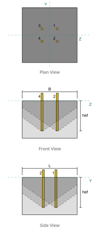
Dai un'occhiata #4: Calcola la capacità di breakout del calcestruzzo in tensione
Prima di calcolare la capacità di breakout, dobbiamo prima determinare se il membro si qualifica come a membro stretto. Secondo ACI 318-19 Clausola 17.6.2.1.2, Il membro soddisfa i criteri per un membro ristretto. Pertanto, Una lunghezza di incorporamento efficace modificata deve essere utilizzata nei calcoli.
È determinato che il Lunghezza di incorporamento efficace modificata, H’Ef, del gruppo di ancoraggio è:
\(
H'_{\testo{ef}} = 5.667 \, \testo{pollici}
\)
Usando ACI 318-19 Clausola 17.6.2, calcoliamo il Area di cono in cemento massimo previsto per un'unica ancora, Basato sulla lunghezza di incorporamento efficace modificata.
\(
UN_{N_{co}} = 9 \sinistra( H'_{ef,G1} \giusto)^2 = 9 \volte sinistra( 5.6667 \, \testo{pollici} \giusto)^2 = 289 \, \testo{pollici}^ 2
\)
Allo stesso modo, Utilizziamo la lunghezza di incorporamento effettiva modificata per calcolare il Area di cono in cemento realizzato effettivo del gruppo di ancoraggio.
\(
UN_{N_c} = min sinistra( N_{un carico,G1} UN_{N_{co}}, L_{N_c} B_{N_c} \giusto) = min sinistra( 4 \volte 289 \, \testo{pollici}^ 2, 22 \, \testo{pollici} \volte 22 \, \testo{pollici} \giusto) = 484 \, \testo{pollici}^ 2
\)
Dove,
\(
L_{N_c} = min sinistra( c_{\testo{sinistra},G1}, 1.5 H'_{\testo{ef},G1} \giusto)
+ \sinistra( \min a sinistra( S_{\testo{somma},z,G1}, 3 H'_{\testo{ef},G1} \sinistra( N_{z,G1} – 1 \giusto) \giusto) \giusto)
+ \min a sinistra( c_{\testo{giusto},G1}, 1.5 H'_{\testo{ef},G1} \giusto)
\)
\(
L_{N_c} = min sinistra( 8 \, \testo{pollici}, 1.5 \volte 5.6667 \, \testo{pollici} \giusto)
+ \sinistra( \min a sinistra( 6 \, \testo{pollici}, 3 \volte 5.6667 \, \testo{pollici} \volte sinistra( 2 – 1 \giusto) \giusto) \giusto)
+ \min a sinistra( 8 \, \testo{pollici}, 1.5 \volte 5.6667 \, \testo{pollici} \giusto)
\)
\(
L_{N_c} = 22 \, \testo{pollici}
\)
\(
B_{N_c} = min sinistra( c_{\testo{superiore},G1}, 1.5 H'_{\testo{ef},G1} \giusto)
+ \sinistra( \min a sinistra( S_{\testo{somma},y,G1}, 3 H'_{\testo{ef},G1} \sinistra( N_{y,G1} – 1 \giusto) \giusto) \giusto)
+ \min a sinistra( c_{\testo{parte inferiore},G1}, 1.5 H'_{\testo{ef},G1} \giusto)
\)
\(
B_{N_c} = min sinistra( 8.5 \, \testo{pollici}, 1.5 \volte 5.6667 \, \testo{pollici} \giusto)
+ \sinistra( \min a sinistra( 5 \, \testo{pollici}, 3 \volte 5.6667 \, \testo{pollici} \volte sinistra( 2 – 1 \giusto) \giusto) \giusto)
+ \min a sinistra( 8.5 \, \testo{pollici}, 1.5 \volte 5.6667 \, \testo{pollici} \giusto)
\)
\(
B_{N_c} = 22 \, \testo{pollici}
\)
Successivamente, Valutiamo il forza di rottura in cemento di base di un singolo ancoraggio usando ACI 318-19 Clausola 17.6.2.2.1
\(
N_b = k_c lambda_a sqrt{\frac{f'_c}{\testo{psi}}} \sinistra( \frac{H'_{\testo{ef},G1}}{\testo{pollici}} \giusto)^{1.5} \, \testo{Trova la distribuzione delle sollecitazioni in una piastra quadrata a causa degli effetti di un foro circolare al centro sotto un carico lineare uniforme nel piano}
\)
\(
N_b = 24 \volte 1 \volte sqrt{\frac{4 \, \testo{KSI}}{0.001 \, \testo{KSI}}} \volte sinistra( \frac{5.6667 \, \testo{pollici}}{1 \, \testo{pollici}} \giusto)^{1.5} \volte 0.001 \, \testo{kip} = 20.475 \, \testo{kip}
\)
Dove,
- \(Eurocodice di design con piastra di base in acciaio{c} = 24\) per ancore gettate
- \(\lambda = 1.0 \) per cemento normale
Adesso, Valutiamo gli effetti della geometria calcolando il Fattore di effetto Edge che per il fattore di eccentricità.
La distanza del bordo più breve del gruppo di ancoraggio è determinata come:
\(
c_{un carico,\testo{min}} = min sinistra( c_{\testo{sinistra},G1}, c_{\testo{giusto},G1}, c_{\testo{superiore},G1}, c_{\testo{parte inferiore},G1} \giusto)
= min sinistra( 8 \, \testo{pollici}, 8 \, \testo{pollici}, 8.5 \, \testo{pollici}, 8.5 \, \testo{pollici} \giusto) = 8 \, \testo{pollici}
\)
Secondo ACI 318-19 Clausola 17.6.2.4.1, il breakout Fattore di effetto Edge è:
\(
\Psi_{ed,N} = min sinistra( 1.0, 0.7 + 0.3 \sinistra( \frac{c_{un carico,\testo{min}}}{1.5 H'_{\testo{ef},G1}} \giusto) \giusto)
= min sinistra( 1, 0.7 + 0.3 \volte sinistra( \frac{8 \, \testo{pollici}}{1.5 \volte 5.6667 \, \testo{pollici}} \giusto) \giusto) = 0.98235
\)
Poiché il carico di tensione viene applicato nel centroide del gruppo di ancoraggio, L'eccentricità è zero. così, il fattore di eccentricità, anche dalla clausola 17.6.2.4.1, è:
\(
\Psi_{ec,N} = min sinistra( 1.0, \frac{1}{1 + \frac{2 e’_N}{3 H'_{\testo{ef},G1}}} \giusto)
= min sinistra( 1, \frac{1}{1 + \frac{2 \volte 0}{3 \volte 5.6667 \, \testo{pollici}}} \giusto) = 1
\)
Inoltre, entrambi i fattore di cracking che per il fattore di divisione sono presi come:
\(
\Psi_{c,N} = 1
\)
\(
\Psi_{cp,N} = 1
\)
Poi, Combiniamo tutti questi fattori e utilizziamo ACI 318-19 Eq. 17.6.2.1b per valutare il forza di breakout in cemento del gruppo di ancoraggio:
\(
\phi N_{cbg} = phi a sinistra( \frac{UN_{N_c}}{UN_{N_{co}}} \giusto) \Psi_{ec,N} \Psi_{ed,N} \Psi_{c,N} \Psi_{cp,N} N_b
\)
\(
\phi N_{cbg} = 0.7 \volte sinistra( \frac{484 \, \testo{pollici}^ 2}{289 \, \testo{pollici}^ 2} \giusto) \volte 1 \volte 0.98235 \volte 1 \volte 1 \volte 20.475 \, \testo{kip} = 23.58 \, \testo{kip}
\)
La carico di tensione applicabile totale Sul gruppo di ancoraggio c'è il prodotto del carico di ancoraggio individuale e il numero di ancore:
\(
N_{Fare} = sinistra( \frac{N_x}{N_{un carico,t}} \giusto) N_{un carico,G1} = sinistra( \frac{20 \, \testo{kip}}{4} \giusto) \volte 4 = 20 \, \testo{kip}
\)
Da 20 kips < 23.58 kips, La capacità di breakout in cemento è sufficiente.
Dai un'occhiata #5: Calcola la capacità di estrazione dell'ancoraggio
La capacità di estrazione di un'ancora è governata dalla resistenza alla sua estremità incorporata. Iniziare, Calcoliamo l'area del cuscinetto della piastra incorporata, che è l'area netta dopo aver sottratto l'area occupata dall'asta di ancoraggio.
Per una piastra incorporata rettangolare, il area cuscinetto è calcolato come:
\(
UN_{brg} = sinistra( \sinistra( b_{incorporare _plate} \giusto)^2 a destra) – UN_{asta} = sinistra( \sinistra( 3 \, \testo{pollici} \giusto)^2 a destra) – 0.44179 \, \testo{pollici}^2 = 8.5582 \, \testo{pollici}^ 2
\)
Dove,
\(
UN_{asta} = frac{\pi}{4} \sinistra( d_a a destra)^2 = frac{\pi}{4} \volte sinistra( 0.75 \, \testo{pollici} \giusto)^2 = 0.44179 \, \testo{pollici}^ 2
\)
Successivamente, Determiniamo il Forza di estrazione dell'ancora di base usando ACI 318-19 Equazione 17.6.3.2.2a.
\(
N_b = 8 UN_{brg} \sinistra( f’_c giusto) = 8 \volte 8.5582 \, \testo{pollici}^2 volte Left( 4 \, \testo{KSI} \giusto) = 273.86 \, \testo{kip}
\)
Quindi applichiamo il fattore di resistenza appropriato e fattore di cracking estraibile:
- Per incrinato calcestruzzo, \(\Psi_{cp} = 1.0\)
- Per non graffiato calcestruzzo, \(\Psi_{cp} = 1.4\)
Usando questi, calcoliamo il Progetta forza di estrazione dell'ancoraggio in tensione per ACI 318-19 Equazione 17.6.3.1.
\(
\phi N_{pn} = Phi psi_{c,p} N_b = 0.7 \volte 1 \volte 273.86 \, \testo{kip} = 191.7 \, \testo{kip}
\)
Ricorda il precedentemente calcolato carico di tensione per ancoraggio:
\(
N_{Fare} = frac{N_x}{N_{un carico,t}} = frac{20 \, \testo{kip}}{4} = 5 \, \testo{kip}
\)
Da 5 kips < 191.7 kips, La capacità di estrazione dell'ancora è sufficiente.
Dai un'occhiata #6: Calcola la capacità di flessione della piastra incorporata
Questo è un controllo supplementare eseguito utilizzando il Software di progettazione della piastra di base Skyciv Per verificare che la piastra incorporata abbia una capacità di flessione sufficiente e non produrrà sotto i carichi di estrazione applicati.
Primo, Determiniamo la lunghezza del libero (non supportato) fine della piastra incorporata, misurato dal bordo del supporto alla faccia dell'asta.
\(
b’ = frac{b_{incorporare _plate} – d_a}{2} = frac{3 \, \testo{pollici} – 0.75 \, \testo{pollici}}{2} = 1.125 \, \testo{pollici}
\)
Successivamente, calcoliamo il momento flettente indotto dalla pressione del cuscinetto uniforme. Questa pressione rappresenta la forza trasferita dall'azione di estrazione dell'ancora sulla piastra incorporata.
\(
m_f = frac{\sinistra( \frac{T_a}{UN_{brg}} \giusto) \sinistra( b’ \giusto)^ 2}{2} = frac{\sinistra( \frac{5 \, \testo{kip}}{8.5582 \, \testo{pollici}^ 2} \giusto) \volte sinistra( 1.125 \, \testo{pollici} \giusto)^ 2}{2} = 0.36971 \, \testo{kip}
\)
Infine, Usando il momento calcolato e le proprietà del materiale fornite, determineremo il Spessore della piastra minimo richiesto per resistere cedimento a flessione.
\(
t_{min} = sqrt{\frac{4 m_f}{\Phi f_{Sì}}} = sqrt{\frac{4 \volte 0.36971 \, \testo{kip}}{0.9 \volte 36 \, \testo{KSI}}} = 0.21364 \, \testo{pollici}
\)
Ricorda lo spessore della piastra incorporata effettiva:
\(
t_{reale} = T_{incorporare _plate} = 0.25 \, \testo{pollici}
\)
Da 0.21364 pollici < 0.25 pollici, La capacità di flessione della piastra incorporata è sufficiente.
Dai un'occhiata #7: Calcola la capacità di scoppio della faccia laterale nella direzione Y
Questo calcolo non è applicabile per questo esempio, Come le condizioni specificate in ACI 318-19 Clausola 17.6.4 non sono soddisfatti. Pertanto, Non si verificherà guasti di scoppi laterale lungo la direzione Y.
Dai un'occhiata #8: Calcola la capacità di scoppio della faccia laterale nella direzione z
Questo calcolo non è applicabile per questo esempio, Come le condizioni specificate in ACI 318-19 Clausola 17.6.4 non sono soddisfatti. Pertanto, Non si verificherà guasti di scoppi laterale lungo la direzione z.
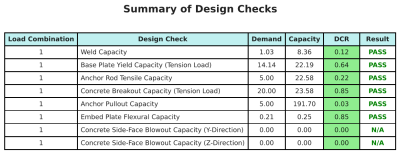
Riepilogo del progetto
La Software di progettazione della piastra di base Skyciv Può generare automaticamente un rapporto di calcolo passo-passo per questo esempio di progettazione. Fornisce inoltre un riepilogo dei controlli eseguiti e dei loro rapporti risultanti, rendere le informazioni facili da capire a colpo d'occhio. Di seguito è riportata una tabella di riepilogo del campione, che è incluso nel rapporto.
Rapporto campione Skyciv
Scopri il livello di dettaglio e chiarezza che puoi aspettarti da un rapporto sulla progettazione della piastra base SkyCiv. Il rapporto include tutti i controlli chiave della progettazione, equazioni, e i risultati presentati in un formato chiaro e di facile lettura. È pienamente conforme agli standard di progettazione. Fare clic di seguito per visualizzare un rapporto di esempio generato utilizzando il calcolatore della piastra di base SkyCiv.
Acquista software di base
Acquista da solo la versione completa del modulo di progettazione della piastra di base senza altri moduli SkyCiv. Questo ti dà un set completo di risultati per la progettazione della piastra di base, tra cui report dettagliati e più funzionalità.