A guide on the Direct Strength Method for Cold Formed Steel
Cold-formed steel member design is challenging due to the complex stability behavior of the thin-walled members. この問題に対処するために、いくつかの方法が開発されています, 直接強度法と同様 (DSM), 最も柔軟で現代的なアプローチ. SkyCiv is committed to help supporting DSM, through resources such as this and software that supports cold formed steel design through this approach.
DSM は、有効幅を計算せずに冷間成形部材の強度を予測します。 [1] (有効幅の計算は、多くの場合、複雑な幾何学的形状を解析するための多くの制限を伴う複雑なプロセスになります。). この方法では, the calculation of critical buckling strength can be carried out in various approaches, 主に有限ストリップ法 (FSM) と有限要素法 (五). このガイドでは, 私たちは探索します:
- 直接力法とは
- Acceptance and Adoption in the Industry
- 従来の有限ストリップ法
- Buckling Mode Types
- What are the DSM Factors?
- SkyCiv セクション ビルダーの有限ストリップ法
直接力法とは (DSM)
の 直接強化法 (DSM) is a design approach used predominately for the analysis and design of cold-formed steel members. Unlike traditional methods (such as the Effective Width Method) that rely on calculating effective section properties to account for local buckling, the DSM directly computes the member’s strength using its full, unreduced cross-sectional properties.
Pros and Cons of Direct Strength Method
| 長所 | 短所 |
|---|---|
| Simplifies Design Process: Reduces complexity by eliminating effective width calculations. | Learning Curve: Requires engineers to become familiar with new concepts and formulations. |
| Enhanced Accuracy: Directly accounts for various buckling modes for precise strength predictions. | Limited Historical Data: Less empirical data available for some specific applications compared to traditional methods. |
| Versatile Application: Suitable for complex and unconventional cross-sections. | Software Dependence: May require advanced software tools not readily available to all practitioners. |
| Unified Methodology: Provides a consistent approach across different buckling behaviors. | Standard Compliance: Not all regional codes may fully incorporate DSM provisions yet. |
| Facilitates Innovation: Encourages the use of new materials and shapes due to its adaptable framework. | Resistance to Change: Industry inertia can slow adoption as practitioners stick to familiar methods. |
Adoption and Acceptance:
The DSM is recognized and incorporated into major international design standards, といった:
- AISI S100: 冷間成形鋼構造部材の設計に関する北米仕様.
- AS / NZS 4600: Australian/New Zealand Standard for Cold-Formed Steel Structures.
DSM is also being prioritised as a future method by being taught in universities and becoming a more common method taught in cold formed design courses. We’re also seeing an increase in it’s support by structural analysis and design software packages who are integrating DSM into their design modules.
しかしながら, there are still some obstacles and challenges in the DSM being widely-adopted, since it is a relatively new/untaught method. Transitioning from traditional methods requires training and adaptation, which some practitioners can be reluctant to undertake.
従来の有限ストリップ法
FSM は FEM を簡略化して作成されました, どちらの方法も同じ理論的背景を持っています, and the FSM is also a matrix method. By defining the nodes and elements of a section it is possible to analyze any complex shape. これによりセクションの最適化が促進され、分析プロセスが簡素化されます。.
いくつかのオプション, オープンソースツールを含む, 現在、有限ストリップ解析を実行できます。. しかしながら, integrating these tools with general analysis and design software has proved challenging due to their complex nature. SkyCiv has recently built a Finite Strip Method analysis tool which is fully integrated into our セクションビルダー ソフトウェア. This tool automates calculation of DSM factors for standard and custom cold-formed sections, allowing for DSM steel design in accordance with AISI S100, なので 4600 and other international standards.
The FSM discretizes the section’s transversal shape into longitudinal strips [3]. This simplifies the traditional 3D analysis problem with 6 degrees of freedom to a problem with 4 自由度. The strips are analyzed for different lengths called half-wavelength.
Using the geometrical section properties, 材料, the stresses, and the load condition, two global matrices are constructed, the elastic stiffness matrix (いつ) and the geometric stiffness matrix (Kg).
最後に, this represents an eigenvalue decomposition problem, ここで、固有値は負荷係数を表します, 固有ベクトルには変形した形状が含まれます.
![]()
Buckling Mode Types
座屈クラスは 3 つの主要なグループに編成されます, グローバル, ローカル, そして歪んでいる, 故障の種類に応じて.
局部座屈: 断面の大きな歪みを伴う座屈, ただし、この歪みには回転のみが含まれます, 翻訳ではありません, 内側の折り線のところで [2].
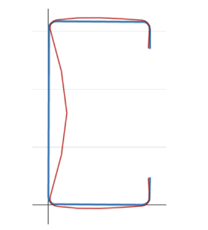
歪み座屈: 断面の大きな歪みを伴う座屈, ただし、この歪みには、部材の 1 つ以上の内部折り線での回転と平行移動が含まれます。 [2].
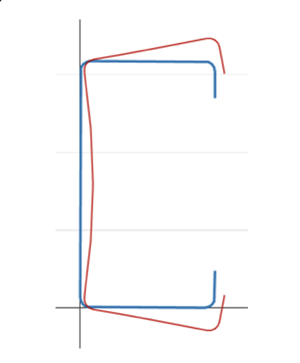
全体的な座屈: 断面歪みを伴わない座屈, 代わりに翻訳 (たわみ) および/または回転 (ねじれ) 断面全体の [2].
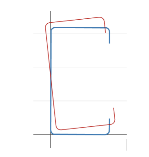
この定義により、座屈分類と変形形状の間に強い幾何学的相関があると推測できます。, シグネチャ カーブの各点の変形を示します。.
DSM Factors
SkyCiv セクション ビルダーの有限ストリップ法
SkyCiv has a Direct Strength Method Calculator built into our Section Analysis Software (SkyCivセクションビルダー) which can automatically calculate the key DSM factors for any custom cold formed steel shape. Simply start from the Section Builder module by loading in a CFS section and clicking Design -> 冷間成形鋼:
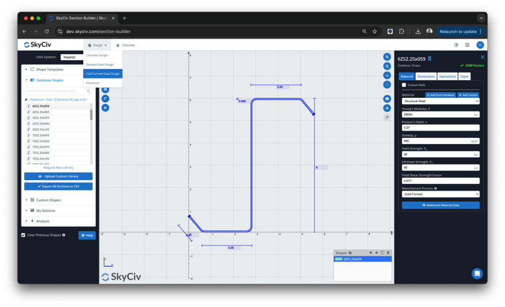
ここから, the DSM factors will be automatically calculated, ready for the user to review and submit:
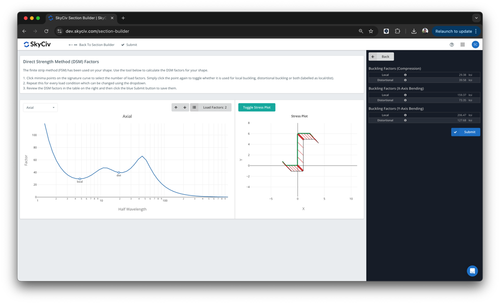
ソフトウェアは SkyCiv Section Builder の上に構築されています, 下 設計 – 冷間成形. 局所的な座屈と歪みの最小値が自動的に検出されます。, ただし、ユーザーはこれらの値をオーバーライドできます. 提出後, これらの要素は SkyCiv AISI の設計に使用されます。 (2016) および AS4600 (2018) 統合された設計モジュール.
SkyCiv 弾性座屈解析モジュール内, ここで明らかにする重要な仮説と考慮事項がいくつかあります. これらについて以下で説明します:
要素のメッシュ
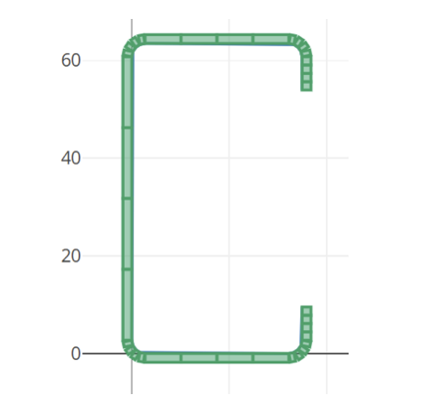
The mesh of the elements is produced automatically and can be viewed in the right chart, フィレットは次のように分割されます 4 要素, そして直線は 4 要素も.
分析の長さ
有限ストリップ解析の実行に使用される長さは、デフォルトで次の対数空間として定義されます。 0 インペリアル単位系では 10^3 まで、およびから 0 メートル法で 10^3.5 まで.
負荷条件
以下の署名曲線を計算します。 5 さまざまな負荷条件:
- アキシアル荷重
- X軸の曲げモーメント, ポジティブ
- X軸の曲げモーメント, ネガティブ
- Y軸の曲げモーメント, ポジティブ
- Y軸の曲げモーメント, ネガティブ
境界条件
解析は、モデルが固定されており、両端が自由に反ることを想定して実行されます。.
署名曲線
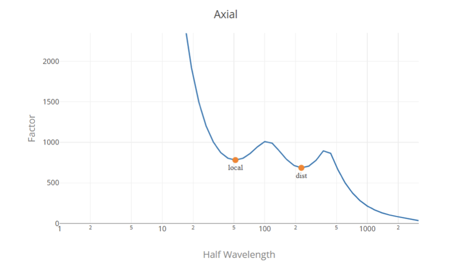
シグネチャ曲線は従来の有限ストリップ法を使用して構築されます。, Fyは正規化されています (Fy = 1) したがって、負荷係数は圧力単位で表示されます。 (単位系による MPa または ksi).
負荷率の選択
一般的に, 負荷係数は署名曲線の極小点です。, 1 つ目は局部座屈の臨界荷重係数を表し、2 つ目は歪み座屈の臨界荷重係数を表します。. シグネチャ曲線には極小点がないため、シグネチャ曲線からグローバル負荷係数を決定することは困難な作業です。. そう, 最も適切な解決策は、有限ストリップ解析からの局所座屈荷重係数と歪み座屈荷重係数、および古典的な公式を使用した全体座屈係数を使用することです。.
アルゴリズムを使用して、署名曲線内の負荷係数を見つけて分類します。. しかしながら, this does not ensure a correct classification in all the cases, and this does not replace the engineering judgment, 送信する前に値を確認し、必要に応じて変更することをお勧めします。.
参考文献
- 冷間成形鋼構造部材の設計に関する北米仕様, 2016 版, アメリカ鉄鋼協会.
- 直接強化法 (DSM) 設計ガイド, 2006, 冷間成形鋼構造部材設計仕様委員会.
- CUFSMを使用した冷間成形鋼部材の座屈解析: 従来の制約付き有限ストリップ法, B.W. シェーファーとS. アダニー, 2006, 18第 1 回冷間成形鋼構造に関する国際専門会議.

