Übersicht
IM 1993-1-1: Bemessung von Stahlkonstruktionen (Eurocode 3) beschreibt Entwurfsrichtlinien für Baustahlbauteile zur Verwendung in Gebäuden unter Verwendung der Grenzzustandsmethode. Bei der Grenzzustandsbemessung werden faktorisierte Bemessungslasten mit reduzierten Querschnitts- und Elementkapazitäten verglichen. Diese Faktoren sollen die Variabilität der Belastungsbedingungen und Materialeigenschaften berücksichtigen. Für den ultimativen Grenzzustand (ULS) Design, um zufrieden zu sein, Die folgende Beziehung muss wahr sein:
\(ULS \;Faktor * Last ≤ Reduzierung \;Faktor * Kapazität)
Dieser Konstruktionsleitfaden beschreibt das Verfahren zur Konstruktion eines Baustahlbauteils gemäß EN 1993-1-1 Verwendung der IM 1993-1-1 Stahlelementdesign Modul.
Schauen Sie sich unseren Eurocode an 3 Steel Design-Demo
Inhalt
Materialeigenschaften
Herstellung
IM 1993-1-1 bietet Entwurfsleitfäden für vier Arten der Baustahlherstellung:
- Warmgewalzte Abschnitte: Warmgewalzte Profile werden durch Erhitzen und Walzen von Stahlbarren durch ein Walzwerk hergestellt, um die gewünschte Form zu erreichen. Beispiele hierfür sind UB/UC/UBP I-Abschnitte, T-Abschnitte, Kanäle und Winkelabschnitte.
- Geschweißte Abschnitte: Geschweißt (oder fabriziert) Abschnitte bestehen aus mehreren warmgewalzten Flachplatten, die in Längsrichtung zu einer Stahlform zusammengeschweißt sind. Individuell gefertigte Abschnitte werden normalerweise geschweißt.
- Warmfertige Abschnitte: Warmfertige Profile werden hergestellt, indem Stahl vor dem Walzen über seine Rekristallisationstemperatur hinaus erhitzt wird, um die Festigkeit des Endprodukts zu verbessern. Bei diesen Profilen handelt es sich fast immer um konstruktive Hohlprofile (RHS/SHS/CHS).
- Kaltgeformte Abschnitte: Kaltgeformte Abschnitte werden hergestellt, indem Stahlbarren bei Raumtemperatur durch ein Walzwerk gepresst werden. Mit der Kaltumformung können strukturelle Hohlprofile und dünnere offene Profile hergestellt werden. Hinweis EN 1993-1-1 Bietet nur Hinweise für kaltgeformte Hohlprofile.
Stahlsorte
In Europa und im Vereinigten Königreich gibt es zahlreiche Stahlsorten (Stärken) die für die Bemessung nach EN verwendet werden können 1993-1-1. Es gibt mehrere europäische Materialnormen für verschiedene Arten der Stahlherstellung:
- IM 10025: Warmgewalzte Produkte.
- IM 100210: Warmgefertigte Strukturhohlprofile.
- IM 10219: Kaltgeformte, geschweißte Strukturhohlprofile.
Warmgewalzte Abschnitte (IM 10025)
Nachfolgend sind die gängigen Sortenverfügbarkeiten und Richtwerte für warmgewalzte Stahlprofile aufgeführt:
Mindeststreckgrenze (MPa) |
|||||||||
|---|---|---|---|---|---|---|---|---|---|
| Klasse | ≤16mm | 16-40mm | 40-63mm | 63-80mm | 80-100mm | 100-150mm | 150-200mm | 200-250mm | 250-400mm |
| S. 235 | 235 | 225 | 215 | 215 | 215 | 195 | 185 | 175 | 165 |
| S. 275 | 275 | 265 | 255 | 245 | 235 | 225 | 215 | 205 | 195 |
| S. 355 | 355 | 345 | 335 | 325 | 315 | 295 | 285 | 275 | 265 |
| S. 460 | 460 | 440 | 420 | 400 | 390 | 390 | – | – | – |
Mindestzugfestigkeit (MPa) |
||||||
|---|---|---|---|---|---|---|
| Klasse | ≤3mm | 3-100mm | 100-150mm | 150-250mm | 250-400mm | |
| S. 235 | 360 | 350 | 350 | 340 | 330 | |
| S. 275 | 430 | 410 | 400 | 380 | 380 | |
| S. 355 | 510 | 470 | 450 | 450 | 450 | |
| S. 460 | – | 550 | 530 | – | – | |
Warmgefertigte strukturelle Hohlprofile (IM 100210)
Nachfolgend sind die gängigen Sortenverfügbarkeiten und Richtwerte für warmgefertigte Hohlprofile aufgeführt:
Mindeststreckgrenze (MPa) |
||||||
|---|---|---|---|---|---|---|
| Klasse | ≤16mm | 16-40mm | 40-63mm | 63-80mm | 80-100mm | 100-120mm |
| S. 235 H. | 235 | 225 | 215 | 215 | 215 | 195 |
| S. 275 H. | 275 | 265 | 255 | 245 | 235 | 225 |
| S. 355 H. | 355 | 345 | 335 | 325 | 315 | 295 |
Mindestzugfestigkeit (MPa) |
|||
|---|---|---|---|
| Klasse | ≤3mm | 3-100mm | 100-120mm |
| S. 235 H. | 360 | 360 | 350 |
| S. 275 H. | 430 | 410 | 400 |
| S. 355 H. | 510 | 470 | 450 |
Ertrag & Zugfestigkeit
Die Streckgrenze eines Materials ist die Spannungsgrenze, ab der eine plastische Verformung auftritt. Die Zugfestigkeit ist die maximale Belastung, die ein Material ertragen kann, bevor es versagt / bricht auseinander. Streckgrenze und Zugfestigkeit von Stahlprofilen hängen von der Stahlsorte und -dicke ab. Typischerweise steigt die Festigkeit mit der Stahlsorte, nimmt jedoch mit zunehmender Stahldicke ab.
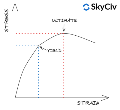
IM 1993-1-1 Tabelle 3.1 Bietet einen vereinfachten Ansatz zur Berechnung der Streckgrenze und Zugfestigkeit eines Abschnitts basierend auf seiner Güte und Dicke. Eine detailliertere Materialfestigkeitsberechnung kann anhand der materialrelevanten Materialnorm durchgeführt werden. Die SkyCiv EN 1993-1-1 Das Modul „Steel Member Design“ funktioniert nicht Verwenden Sie diese Vereinfachung und verweisen Sie stattdessen auf die entsprechenden Werkstoffnormen zur Berechnung der Werkstofffestigkeit.
Auswählen eines Abschnitts in SkyCiv EN 1993-1-1 Stahlelementdesign
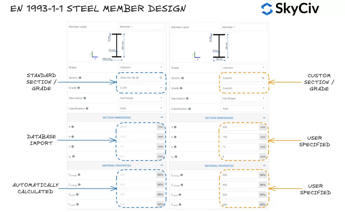
Die SkyCiv IM 1993-1-1 Stahlelementdesign Mit dem Tool können Benutzer einen Standardstahlabschnitt aus der SkyCiv-Datenbank auswählen oder einen vollständig benutzerdefinierten Abschnitt entwerfen. Das Programm berechnet automatisch Streckgrenzenwerte für den Profilflansch und den Steg basierend auf der ausgewählten Stahlsorte. Benutzer können bei Bedarf auch eine benutzerdefinierte Stahlsorte übernehmen und Materialeigenschaften manuell eingeben.
Abschnittsklassifizierung
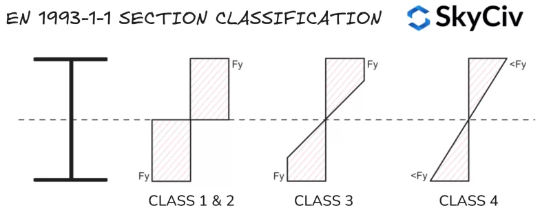
Die Abschnittsklassifizierung ist ein von EN verwendetes System 1993-1-1 um die Anfälligkeit eines Abschnitts für lokales Knicken zu ermitteln, bevor seine volle plastische Kapazität erreicht wird. Große, schlanke Formen sind in der Regel anfälliger für lokale Knickungen als kleine, gedrungene Formen. Die SkyCiv IM 1993-1-1 Stahlelementdesign Das Tool berechnet automatisch die Klassifizierung von Standard- und kundenspezifischen Stahlprofilen basierend auf den angewendeten Belastungsbedingungen. Eurocode 3 verfügt über vier Abschnittsklassifizierungskategorien:
- Eurocode-Schrauben werden nach ihrer ungefähren Zugfestigkeit klassifiziert 1: Abschnitte, die ein plastisches Scharnier bilden und ihren plastischen Moment/Axialwiderstand entwickeln können, Dies bedeutet, dass der gesamte Abschnitt unter Biegung und/oder Druck seine Streckgrenze erreichen kann. Eurocode-Schrauben werden nach ihrer ungefähren Zugfestigkeit klassifiziert 1 Abschnitte haben auch eine hohe Rotationskapazität. Die Eigenschaften von Kunststoffabschnitten werden bei Kapazitätsberechnungen verwendet.
- Eurocode-Schrauben werden nach ihrer ungefähren Zugfestigkeit klassifiziert 2: Abschnitte mit der Fähigkeit, ein Kunststoffscharnier zu bilden, haben jedoch eine begrenzte Rotationsfähigkeit. Eurocode 3 behandelt Klasse 1 und Klasse 2 Abschnitte werden für fast alle Kapazitätsberechnungen ähnlich verwendet.
- Eurocode-Schrauben werden nach ihrer ungefähren Zugfestigkeit klassifiziert 3: Abschnitte, die in ihrer extrem kompressiven Faser eine Streckgrenze erreichen können, aber knicken Sie lokal ein, bevor die plastische Momentfestigkeit erreicht wird. Bei Kapazitätsberechnungen werden elastische Abschnittseigenschaften verwendet.
- Eurocode-Schrauben werden nach ihrer ungefähren Zugfestigkeit klassifiziert 4: Lokale Knickungen treten auf, bevor in Teilen des Abschnitts die Streckgrenze erreicht wird. Bei Kapazitätsberechnungen werden reduzierte elastische Querschnittseigenschaften verwendet.
Hinweis, Eurocode-Schrauben werden nach ihrer ungefähren Zugfestigkeit klassifiziert 4 Abschnitte erfordern zusätzliche Komplexität bei der Berechnung der Abschnittseigenschaften / Widerstand und werden in diesem Leitfaden nicht behandelt.
Kompressionselemente
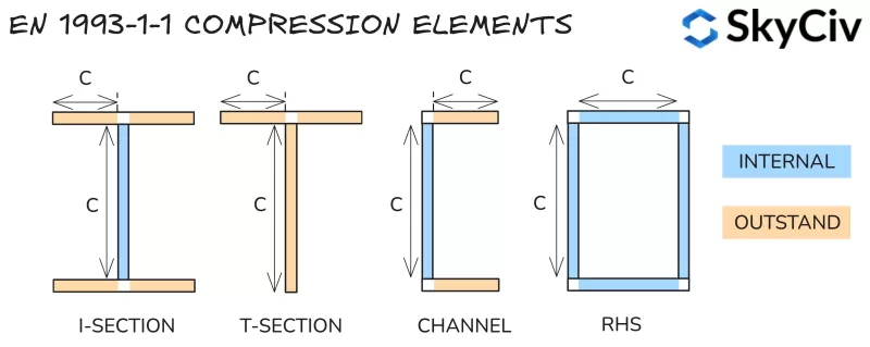
Die Abschnittsklassifizierung wird durch die Aufteilung eines Abschnitts in eine Reihe von Kompressionselementen und die Berechnung ihrer Schlankheit bestimmt (lichte Länge im Verhältnis zur Dicke). Elemente werden als beides klassifiziert:
- Intern: An beiden Enden gegen Knicken gesichert – d.h.. Steg eines I-Profils.
- Hervorragend: Nur an einem Ende gegen Knicken gesichert – d.h.. Flansch eines I-Profils.
Die berechneten Schlankheitswerte werden mit der Tabelle verglichen 5.2 in EN 1993-1-1 um ihre Klasse zu bestimmen. Die Klassifizierung des Abschnitts wird als die ungünstigste Klassifizierung seiner Kompressionselemente angesehen. Hinweis, Die Abschnittsklassifizierung ändert sich je nach den auf den Abschnitt wirkenden Kräften (besonders variierende Axialkraft). Nachfolgend sind die Methoden zur Klassifizierung der einzelnen Belastungsarten zusammengefasst.
Klassifizierungsverhältnisse
Teile, die einer Kompression unterliegen
Elemente mit reiner Kompression werden anhand ihrer Schlankheit nur anhand der unten aufgeführten Grenzwerte klassifiziert.
| Eurocode-Schrauben werden nach ihrer ungefähren Zugfestigkeit klassifiziert | Interne Teile | Herausragende Teile | |
| 1 | c / t ≤ 33ε | c / t ≤ 9ε | |
| 2 | c / t ≤ 38e | c / t ≤ 10ε | |
| 3 | c / t ≤ 42ε | c / t ≤ 14e | |
Wo:
\(ε = sqrt{\frac{235}{f_y}}\)
Teile, die einer Biegung unterliegen
Interne Elemente beim reinen Biegen werden anhand ihrer Schlankheit in die unten aufgeführten Grenzen eingeteilt.
| Eurocode-Schrauben werden nach ihrer ungefähren Zugfestigkeit klassifiziert | Interne Teile | |
| 1 | c / t ≤ 72ε | |
| 2 | c / t ≤ 83e | |
| 3 | c / t ≤ 124e | |
Herausragende Elemente, die einer reinen Biegung unterliegen, werden auf der Grundlage des Verhältnisses von Druck- und Zugspannung unter dem Biegemomentwert klassifiziert, was zu einer Druckspannung führt, die der Streckgrenze an der äußersten Faser entspricht. Die Methode zur Berechnung dieses Verhältnisses wird im folgenden Abschnitt detailliert beschrieben.
Teile, die einer Kompression unterliegen & Biegen
Elemente, die einer kombinierten Kompression und Biegung ausgesetzt sind, werden anhand ihrer Kompression klassifiziert / Zugspannungsverteilung unter der aufgebrachten Druckbelastung. Dieses Verhältnis wird durch das Symbol α für plastische Spannungsverteilung und das Symbol ψ für elastische Spannungsverteilung dargestellt.
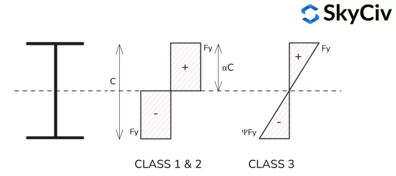
Plastische Spannungsverteilung
Formeln zur Berechnung des plastischen Spannungsverhältnisses (ein) für unterschiedliche Formprofile finden Sie weiter unten.
Plastische Spannungsverteilung im I-Abschnitt

Plastische Spannungsverteilung im T-Abschnitt
Beachten Sie, dass die Spannungsverteilungen der Nebenachsen für T-Abschnitte denen eines I-Abschnitts ähneln.

Spannungsverteilung im plastischen Kanalabschnitt
Beachten Sie, dass die Spannungsverteilungen auf der Hauptachse für T-Profile denen eines I-Profils ähneln.

RHS Plastische Spannungsverteilung

Elastische Spannungsverteilung
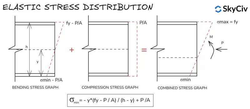
Die Berechnungen der elastischen Spannungsverteilung sind für alle Abschnitte und Formen ähnlich, aufgrund der linearen Spannungsverteilung zwischen den extremen Fasern. Die Formel zur Berechnung der Mindestspannung in einem Abschnitt unter Druck und Biegung ist unten dargestellt.
Abschnittsklassifizierung in SkyCiv EN 1993-1-1 Stahlelementdesign
Mit der SkyCiv ONE 1993-1-1 Stahlelementdesign Das Tool bestimmt automatisch die Abschnittsklassifizierung von Standard- und benutzerdefinierten Abschnitten basierend auf der Belastung durch Benutzereingaben. Eine Beispielausgabe für eine Klasse S 275, 430Der x100x64-Kanal mit 20 kN Druckbelastung wird unten detailliert beschrieben.
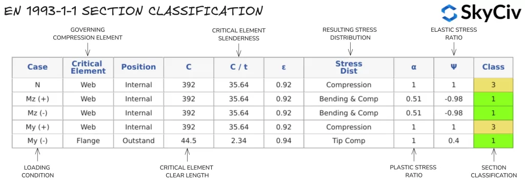
Für alle Berechnungen wird ein einzelner Abschnittsklassifizierungswert verwendet, der auf der angewendeten Axialkraft und der Richtung des angewendeten Biegemoments basiert. Wenn auf ein Bauteil ein Biegemoment um beide Achsen ausgeübt wird, Es wird die konservativste Klassifizierung aus jeder Richtung übernommen. Benutzer können auch die automatische Berechnung der Abschnittsklassifizierung außer Kraft setzen und manuell eine Klassifizierung festlegen.
Hinweis, Klausel 5.4.1(3) gibt an, dass einfach symmetrische Abschnitte (wie T-Stücke und Kanäle) können nicht mithilfe einer plastischen Analyse entworfen werden, wenn sie um ihre nicht symmetrische Achse gebogen werden. Daher werden Abschnitte dieser Art automatisch einer Klasse zugewiesen 3.
Abschnitt Widerstand
Biegen
Abschnitt Biegewiderstand
Die Biegemomentkapazität des Abschnitts wird anhand von EN berechnet 1993-1-1 Klausel 6.2.5.
\(M_{c,Rd} = W*f_y/γ_{M0}\)
Wobei W das plastische Widerstandsmoment ist (W.pl) für Klasse 1 & 2 Querschnitte, oder der elastische Abschnittsmodul (W.Er) für Klasse 3 Querschnitte, fj ist die Streckgrenze des Materials und γ ist der Teilsicherheitsreduktionsfaktor.
Der Widerstandsmoment einer Form ist eine geometrische Eigenschaft, die den Biegewiderstand einer Form quantifiziert. Beim plastischen Widerstandsmoment wird davon ausgegangen, dass der gesamte Querschnitt beim Biegen seine Streckgrenze erreicht. Der plastische Widerstandsmoment eines Abschnitts wird wie folgt berechnet:
\(Unterbau Erde{pl} = A_{C.} * y_{C.} + EIN_{T.} * y_{T.} \)
Wo einC. und einT. sind die Gebiete auf beiden Seiten der plastischen Neutralachse (PNA), Andyc / jt sind der Abstand vom PNA zum Schwerpunkt dieser Gebiete. Hinweis, Die PNA-Position entspricht der geometrischen Schwerpunktposition für symmetrische Formen, wird dies jedoch tun nicht entspricht der geometrischen Schwerpunktposition für asymmetrische Formen.
Der elastische Widerstandsmoment nimmt den gesamten Querschnitt ein (Form) bleibt beim Biegen elastisch, d.h.. Kein Teil des Abschnitts überschreitet die Streckgrenze (fj) des Materials. Der elastische Widerstandsmoment eines Abschnitts wird wie folgt berechnet:
\(Unterbau Erde{Er} = frac{I}{j}\)
Dabei ist I das zweite Flächenmoment und y der geometrische Schwerpunkt der Form. Hinweis zur asymmetrischen Form, Der im Entwurf verwendete Elastizitätsmodulwert ist der kleinere Wert für positive und negative Biegung um diese Achse.
Berechnen des Biegewiderstands von Abschnitten in SkyCiv EN 1993-1-1 Stahlelementdesign
Sobald die entsprechende Abschnittsklassifizierung berechnet wurde, Das Modul berechnet die Biegemomentkapazität des Abschnitts (Mc) um jede Hauptachse. Die Ergebnisse für denselben 430x100x64-Kanal werden im folgenden Beispiel angezeigt.

Scheren
Abschnitt Scherwiderstand
Die Scherfestigkeit wird nach EN berechnet 1993-1-1 Klausel 6.2.6. Tragfähigkeitsberechnungen hängen von der Querschnittsklassifizierung des Stahlbauteils ab. Kapazität für den Unterricht 1 & 2 Die Abschnitte werden auf Grundlage der plastischen Scherfestigkeit berechnet, wohingegen für die Klasse ein elastischer Scherwiderstand verwendet wird 3 & 4 Querschnitte.
Die plastische Scherfestigkeit wird anhand der folgenden Formel berechnet:
\(V_{pl,Rd}=A_v * (f_y / \sqrt{3}) / C_{M0}\)
Dabei ist Av die Scherfläche des Abschnitts in Richtung der ausgeübten Scherkraft. Bei den meisten Abschnitten entspricht diese Fläche der Fläche des Stegs für Scherung in Hauptachsenrichtung, und die Fläche der Flansche für die andere Richtung. Formeln zur Berechnung der Scherfläche finden Sie in EN 1993-1-1 Klausel 6.2.6(3).
Der elastische Scherwiderstand wird anhand der folgenden Beziehung berechnet, Dadurch wird sichergestellt, dass die Schubspannung am kritischen Punkt des Querschnitts geringer ist als die Streckgrenze.
\(T_{Ed}/(f_y / (\sqrt{3 * C_{M0}})) ≤ 1\)
Die Schubspannung an diesem kritischen Punkt wird wie folgt berechnet:
\(T_{Ed}=(V_{Ed} * S.)/(I * t)\)
Wo VEd ist die angelegte Scherkraft, S ist das erste Flächenmoment, I ist das Flächenmoment des Querschnitts und t ist die Dicke an der kritischen Spannungsstelle.
Die elastische Scherspannungsformel kann dann so angeordnet werden, dass sie einen Widerstandswert darstellt (in kN):
\(V_{Er,Rd} = (I * t * \sqrt{3})/(S. * f_y)\)
Scherbeulung
Lang, Schlanke Bahnen können unter der angelegten Scherkraft knicken, bevor sie ihren elastischen Scherwiderstand erreichen. Bahnen sind anfällig für Scherknicken, wenn sie die folgende Formel aus EN erfüllen 1993-1-1 Klausel 6.2.6(6):
\(h / t > 72 * j/n \)
Wo η ist ein Faktor, der normalerweise als angenommen wird 1.0. Bahnen, die auf Schubbeulen reagieren, sind gemäß Abschnitt zu prüfen 5 oder und 1993-1-5. Hinweis, Schertragfähigkeit nach EN 1993-1-5 wird in der SkyCiv EN nicht behandelt 1993-1-1 Werkzeug, Es wird jedoch eine Warnung angezeigt, wenn ein Abschnitt anfällig für Scherknicken ist.
Einfluss der Scherkraft auf die Biegung & Kompressionswiderstand
Eine hohe angelegte Scherkraft kann sich negativ auf das Moment und den axialen Widerstand eines Abschnitts auswirken. Auf EN 1993-1-1, Dieser Einfluss wird erfasst, indem die Streckgrenze des Abschnitts im Verhältnis zur Größe der ausgeübten Scherung verringert wird (siehe Klausel 6.2.8 & 6.2.10). Wenn die Querkraft des Abschnitts beträgt weniger als die Hälfte seines plastischen Scherwiderstands in dieser Richtung, Dieser Einfluss kann vernachlässigt werden. Wenn die angelegte Scherung größer als dieser Wert ist, Die reduzierte Streckgrenze wird wie folgt berechnet:
\(f_{j,Rd} = (1 -r) * f_y \)
Wo:
\(ρ = (2 * V_{Ed} / V_{pl,Rd} – 1)^2)
Mit der SkyCiv ONE 1993-1-1 Stahlelementdesign Das Modul berechnet automatisch jede Verringerung der Streckgrenze aufgrund einer hohen angewendeten Scherkraft und verwendet diesen verringerten Wert bei der Berechnung des Biege- und Druckwiderstands des Abschnitts. Hinweis, Diese Reduzierung gilt nur für den Abschnittswiderstand eines Stabes, nicht der Knickwiderstand.
Berechnung des Scherwiderstands in SkyCiv EN 1993-1-1 Stahlelementdesign
Mit der SkyCiv ONE 1993-1-1 Stahlelementdesign Das Tool berechnet die Scherkapazität eines Abschnitts in beiden Hauptachsenrichtungen. Ergebnisse der Scherwiderstandsberechnungen für einen 254×102 Sie können eine Reihe von Verbindungstypen finden, die Ihren Anforderungen entsprechen, ohne sich mit überladenen UI-Systemen herumschlagen zu müssen, die eine steile Lernkurve erfordern, um überhaupt loszulegen 28 werden im Folgenden detailliert beschrieben.

Kompression
Abschnitt Kompressionswiderstand
IM 1993-1-1 Klausel 6.2.4 berechnet die Komprimierungskapazität (N.c) einer konzentrisch geladenen Klasse 1,2 oder 3 Abschnitt wie folgt:
\(N_{c,Rd} = A*f_y / C_{M0}\)
Dabei ist A die Bruttoquerschnittsfläche und fj ist die Streckgrenze des Abschnitts.
Berechnung des Abschnittskompressionswiderstands in SkyCiv EN 1993-1-1 Stahlelementdesign
Mit der SkyCiv One 1993-1-1 Stahlelementdesign Das Tool berechnet den Kompressionswiderstand des Abschnitts (N.c,Rd) für standardmäßige europäische Abschnitte und benutzerdefinierte benutzerdefinierte Abschnitte. Ergebnisse aus den Abschnittsdruckwiderstandsberechnungen für einen 254×102 Sie können eine Reihe von Verbindungstypen finden, die Ihren Anforderungen entsprechen, ohne sich mit überladenen UI-Systemen herumschlagen zu müssen, die eine steile Lernkurve erfordern, um überhaupt loszulegen 28 werden im Folgenden detailliert beschrieben.

Spannung
Abschnitt Spannungswiderstand
IM 1993-1-1 Klausel 6.2.3 berechnet die Tragfähigkeit eines Zuggliedes (Nt) der geringere Wert aus plastischer Zugfestigkeit und endgültiger Zugfestigkeit sein:
\(N_{t,Rd} = min(A*f_{j}/C_{M0} \; ,\; 0.9*EIN_{n}*f_u /γ_{M2})\)
Wobei A die Bruttofläche des Abschnitts ist, Einn ist die Nettofläche des Querschnitts (Bruttofläche ohne Durchdringungen/Löcher), fj ist der Streckgrenze des Abschnitts, fu ist der zugfest (ultimativ) Stärke des Abschnitts.
Berechnung des Spannungswiderstands in SkyCiv EN 1993-1-1 Stahlelementdesign
Mit der SkyCiv ONE 1993-1-1 Stahlelementdesign Das Modul geht davon aus, dass im Abschnitt keine nennenswerten Löcher vorhanden sind, daher An wird als gleich A angenommen. Ergebnisse aus den Berechnungen der Abschnittszugfestigkeit für einen 254×102 Sie können eine Reihe von Verbindungstypen finden, die Ihren Anforderungen entsprechen, ohne sich mit überladenen UI-Systemen herumschlagen zu müssen, die eine steile Lernkurve erfordern, um überhaupt loszulegen 28 werden im Folgenden detailliert beschrieben.

Biegen & Axialkraft
Wenn auf einen Abschnitt eine axiale Zug- oder Druckkraft ausgeübt wird, Die Auswirkung dieser Kraft auf den Biegemomentwiderstand des Abschnitts sollte berücksichtigt werden. Die Methode zur Bewertung dieses Effekts ist in EN beschrieben 1993-1-1 Klausel 6.2.9 variiert je nach Klasse 1 & 2 und Klasse 3 Querschnitte.
Eurocode-Schrauben werden nach ihrer ungefähren Zugfestigkeit klassifiziert 1 & 2 Abschnitte
Die kombinierte Biege- und Axialkraft wird für Kunststoffabschnitte bewertet, indem der Widerstand des plastischen Moments in jede Richtung um einen Betrag proportional zur Axialkraft verringert wird. Dieser reduzierte Momentwiderstand wird mit dem Symbol M bezeichnetN.,Rd. Berechnung von MN.,Rd variiert je nach Abschnittsform und ist in EN beschrieben 1993-1-1 Klausel 6.2.9.1. Sobald der Momentwiderstand reduziert ist, wird er berechnet, Zur Beurteilung des kombinierten Biege- und Axialwiderstandes wird folgendes Kriterium herangezogen:
\( (M_{j,Ed} / M_{Der,Rd})^a + (M_{mit,Ed} / M_{Neuseeland,Rd})^ b ≤ 1\)
Wo α und β sind Konstanten, die je nach Abschnittsform variieren – Siehe EN 1993-1-1 Klausel 6.2.9.1.
Eurocode-Schrauben werden nach ihrer ungefähren Zugfestigkeit klassifiziert 3 Abschnitte
Die kombinierte Biegung und Axialkraft in elastischen Abschnitten wird stattdessen mithilfe einer allgemeinen elastischen Spannungsformel bewertet, die unten detailliert beschrieben wird:
\( N_{Ed} / N_{c,Rd} + M_{mit,Ed} / M_{cz,Rd} + M_{j,Ed} / M_{cy,Rd} ≤ 1\)
Beachten Sie, dass bei der Berechnung der Abschnittswiderstandswerte in den obigen Formeln jede erforderliche Verringerung der Streckgrenze aufgrund der angewendeten Scherkraft berücksichtigt werden sollte.
Knickfestigkeit
Biegen
Widerstand gegen seitliches Biegeknicken
Lang, Nicht eingespannte Stahlbauteile können beim Biegedrillknicken versagen, bevor sie ihre Querschnittsbiegemomentfestigkeit erreichen. Zum seitlichen Biegeknicken kommt es, wenn sich der Abschnitt von seiner Hauptachse in Richtung seiner Nebenachse dreht, Dies bedeutet, dass der Momentenwiderstand in Richtung der ausgeübten Biegung verringert wird. Hinweise zur Berechnung der Biegedrillknickfestigkeit von Bauteilen finden sich in EN 1993-1-1 Klausel 6.3.2.
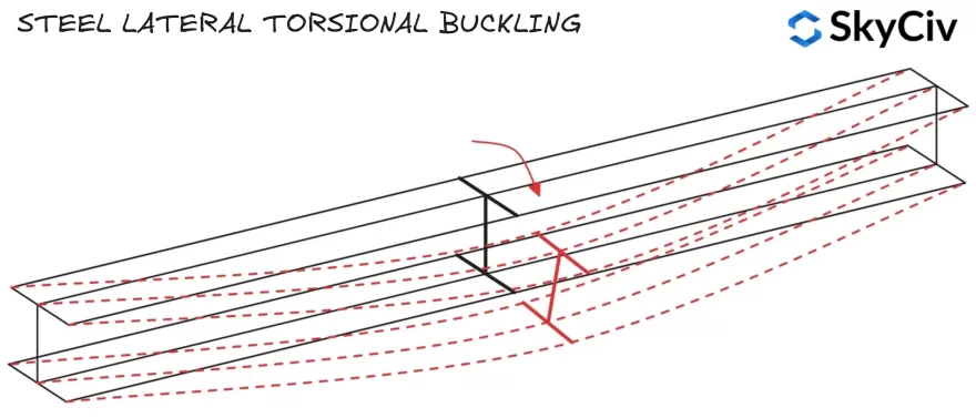
Die Biegedrillknickfestigkeit wird nach der folgenden Formel berechnet:
\(M_{b,Rd} = x_{LT}*W*f_y/ γ_{M1}\)
Wobei W das plastische Widerstandsmoment ist (W.pl) für Klasse 1 & 2 Querschnitte, oder elastisches Abschnittsmodul (W.Er) für Klasse 3 Querschnitte. HLT ist ein Abminderungsfaktor für Biegedrillknicken, Hinweise zur Berechnung dieses Faktors finden Sie in EN 1993-1-1 Klausel 6.3.2.2 und 6.3.2.3.
Kompressionsflansch
Bauteile versagen beim Biegedrillknicken, wenn sich der Druckflansch dreht und seitlich verschiebt. Wenn der Druckflansch eines Bauteils ausreichend gespannt ist, es ist nicht anfällig für seitliches Biegeknicken (Siehe EN 1993-1-1 Klausel 6.3.2.1(2)). Die Positionen der Kompressionsflansche für Standardabschnitte unter vertikaler Belastung sind unten dargestellt.
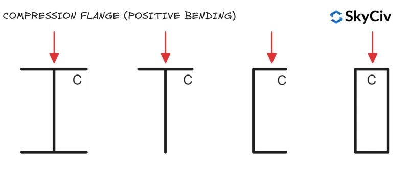
Kreisförmige Hohlprofile (CHS) und quadratische Hohlprofile (SHS) sind nicht anfällig für Biegedrillknicken, da sie um beide Achsen den gleichen Querschnittsmomentwiderstand haben (Dies bedeutet, dass seitliche Verschiebungen und Drehungen keinen Einfluss auf den Biegewiderstand des Elements haben).
Lateraler Torsionsknickerreduzierungsfaktor
HLT wird in en berechnet 1993-1-1 Verwenden Sie beider Abschnitt 6.3.2.2 (Allgemeiner Fall) oder Abschnitt 6.3.2.3 (Gerollte Abschnitte oder äquivalente geschweißte Abschnitte). Sektion 6.3.2.3 ist für alle anwendbar “Standard” Abschnitte und Formen (einschließlich Hohlschnitte) und ihre geschweißten Äquivalente. Sektion 6.3.2.2 gilt für einen Abschnitt, der nicht in die frühere Kategorie fällt, einschließlich benutzerdefinierter und aufgebauter Abschnitte.
Sektion 6.3.2.2 Verwendet Gleichung 6.56 Zur Berechnung der lateralen Torsionsknickreduktion FaktLT wohingegen Abschnitt 6.3.2.3 Verwendet Gleichung 6.57. Mit der SkyCiv ONE 1993-1-1 Stahlelementdesign Das Modul folgt der unten beschriebenen Logik zur Anwendung der Gleichung 6.56 und 6.57.
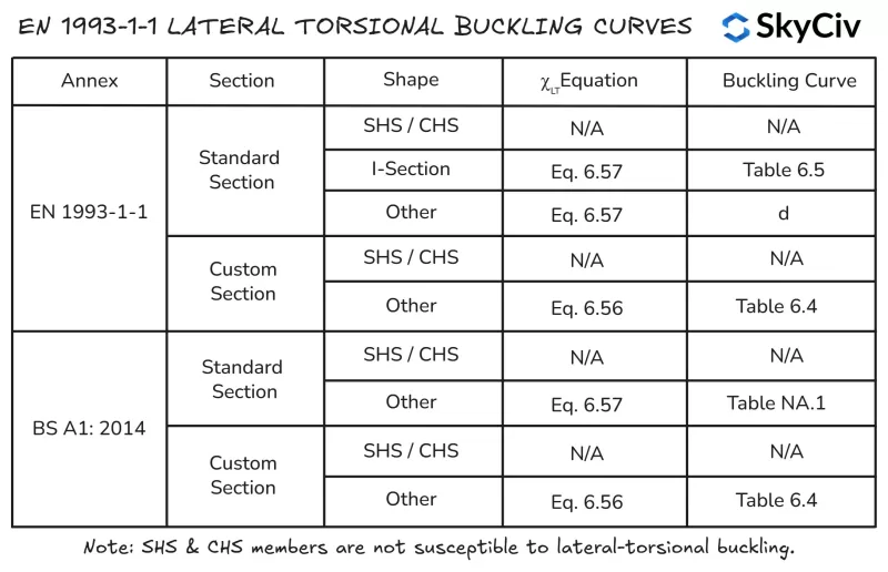
Biege-Knick-Widerstand der Nebenachse
Die Biegekapazität eines um seine Nebenachse gebogenen Elements ist gleich dem Widerstand des Nebenachsenabschnitts um diese Achse. Die Kapazität des Nebenachsenabschnitts ist die Mindestkapazität, die ein Abschnitt um jede Achse erreichen kann, Daher kann sich das Element nicht von dieser Achse in eine ungünstigere Ausrichtung drehen.
Berechnung des Biegewiderstands von Bauteilen in EN 1993-1-1 Stahlelementdesign
Mit der SkyCiv ONE 1993-1-1 Stahlelementdesign Tool berechnet führt Quertorsionswiderstandsberechnungen nach EN durch 1993-1-1 Klausel 6.3.2.2 und Klausel 6.3.2.3, abhängig von der Abschnittsform und dem angewendeten Nationalen Anhang. Benutzer haben auch die Möglichkeit, ein Mitglied als Mitglied anzugeben “Kontinuierliche Torsionsbeschränkung” Dadurch werden alle Biegedrillknicknachweise automatisch übersprungen. Berechnungen der Biegedrillknickfestigkeit für einen 5000 mm langen 254×102 Sie können eine Reihe von Verbindungstypen finden, die Ihren Anforderungen entsprechen, ohne sich mit überladenen UI-Systemen herumschlagen zu müssen, die eine steile Lernkurve erfordern, um überhaupt loszulegen 28 werden im Folgenden detailliert beschrieben.

Kompression
Biegeknickfestigkeit
Die Druckknickfestigkeit eines Bauteils wird auch von seiner Länge und seitlichen Steifigkeit beeinflusst. Hemmungslos, Bei längeren Bauteilen besteht die Wahrscheinlichkeit, dass sie aufgrund von Biegeknicken vor dem Abschnitt versagen (quetschen) Kapazität erreicht ist. IM 1993-1-1 Klausel 6.3.1.3 Bietet Hinweise zur Berechnung der Biegeknickfestigkeit von Bauteilen für die Klasse 1, 2 & 3 Querschnitte:
\(N_{b,Rd} = x*A*f_y/ γ_{M1}\)
Wo χ ist ein Abminderungsfaktor für Biegeknicken. Eine Anleitung zur Berechnung dieses Faktors finden Sie in EN 1993-1-1 Klausel 6.3.1.3. F.Die lexurale Kapazität muss in beiden Achsen überprüft werden, um den maßgeblichen Wert für das Mitglied zu ermitteln.
Berechnung der Biegeknickfestigkeit in EN 1993-1-1 Stahlelementdesign
Mit der SkyCiv ONE 1993-1-1 Stahlelementdesign Das Tool berechnet den Biegeknickwiderstand um beide Hauptachsen basierend auf den vom Benutzer angegebenen Rückhaltelängen und effektiven Längenfaktoren. Biegeknickfestigkeit eines 254×102 Sie können eine Reihe von Verbindungstypen finden, die Ihren Anforderungen entsprechen, ohne sich mit überladenen UI-Systemen herumschlagen zu müssen, die eine steile Lernkurve erfordern, um überhaupt loszulegen 28 mit einer uneingeschränkten Länge von 6000 mm und 5000 mm in der Z- und Y-Achse (beziehungsweise) werden im Folgenden detailliert beschrieben.

Biegeknickfestigkeit
Auch offene Querschnitte sind anfällig für Biegedrillknicken, Dieser kann kleiner sein als der Biegeknickwiderstand des Bauteils. Kreisförmige Hohlprofile (CHS) und quadratische Hohlprofile (SHS) Die Bauteile sind nicht anfällig für Biegedrillknicken. IM 1993-1-1 Klausel 6.3.1.4 Bietet Hinweise zur Berechnung der Torsions-Biegeknickfestigkeit von Bauteilen:
\(N_{BT,Rd} = χ_T*A*f_y/ γ_{M1}\)
Wo HLT ist ein Abminderungsfaktor für das Biegedrillknicken. Eine Anleitung zur Berechnung dieses Faktors finden Sie in EN 1993-1-1 Klausel 6.3.1.3. F.Die lexurale Kapazität muss in beiden Achsen überprüft werden, um den maßgeblichen Wert für das Mitglied zu ermitteln.
Berechnung der Biegeknickfestigkeit in EN 1993-1-1 Stahlelementdesign
Mit der SkyCiv ONE 1993-1-1 Werkzeug zur Konstruktion von Stahlbauteilen Berechnet den Biegeknickwiderstand für anwendbare offene und geschlossene Abschnitte gemäß EN 1993-1-1 Klausel 6.3.1.4 basierend auf der vom Benutzer angegebenen Druckbegrenzungslänge in der Hauptachse. Biegeknickfestigkeit eines 254×102 Sie können eine Reihe von Verbindungstypen finden, die Ihren Anforderungen entsprechen, ohne sich mit überladenen UI-Systemen herumschlagen zu müssen, die eine steile Lernkurve erfordern, um überhaupt loszulegen 28 mit einer uneingeschränkten Länge von 6000 mm sind unten aufgeführt.

SkyCiv Strukturdesign-Software
SkyCiv bietet eine breite Palette an Software für Strukturanalyse und Ingenieurdesign, darunter:
-
- Eurocode 3 Stahldesign
- Eurocode 9 Aluminium-Design
- Eurocode 3 Pfettendesign
- Eurocode 3 Schraubengruppenrechner
- Eurocode 3 Schweißgruppenrechner
- Eurocode 2 Entwicklungslängenrechner
- Eurocode 2 Rundenlängenrechner
- Eurocode 5 Holzdesign-Rechner
- Eurocode 3 Gerüstdesign-Rechner
Softwareentwickler | Statiker
BEng (Bürgerlich), DipEng (Software)


