Basisplatten -Designbeispiel unter Verwendung von AISC 360-22 und ACI 318-19
Problemanweisung
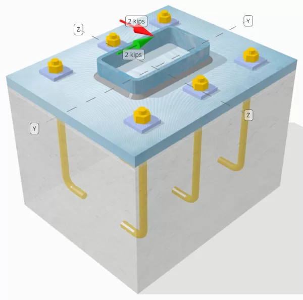
Bestimmen Sie, ob die entworfene Verbindung zu Base-Plattenverbindung für a ausreicht Vy=2-Kip und Vz=2-Kip Querlasten.
Gegebene Daten
Spalte:
Spaltenabschnitt: HSS7X4X5/16
Säulenbereich: 7.59 im2
Säulenmaterial: A36
Grundplatte:
Grundplattenabmessungen: 12 in x 14 im
Grundplattendicke: 3/4 im
Grundplattenmaterial: A36
Fugenmörtel:
Fugendicke: 0.25 im
Beton:
Konkrete Abmessungen: 12 in x 14 im
Betondicke: 10 im
Betonmaterial: 3000 psi
Geknackt oder ungekrönt: Geknackt
Anker:
Ankerdurchmesser: 1/2 im
Effektive Einbettungslänge: 8 im
Dicke der Plattenscheibe: 0.25 im
Anschluss für Tellerwaschanlage: Mit der Grundplatte verschweißt
Schweißnähte:
Schweißnahtgröße: 1/4 im
Füllmetallklassifizierung: E70XX
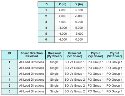
Ankerdaten (von Skyciv -Taschenrechner):
Modell im kostenlosen SkyCiv-Tool
Modellieren Sie noch heute das oben stehende Grundplattendesign mit unserem kostenlosen Online-Tool! Keine Anmeldung erforderlich.
Definitionen
Lastpfad:
Das Design folgt den Empfehlungen von AISC-Designhandbuch 1, 3RD Edition, und ACI 318-19. Auf die Säule einwirkende Scherkräfte werden über die Schweißnähte auf die Grundplatte übertragen, und dann zum tragenden Beton durch Ankerstangen. Reibung und Scherlugs werden in diesem Beispiel nicht berücksichtigt, Da diese Mechanismen in der aktuellen Software nicht unterstützt werden.
Standardmäßig, die angewandte Die Querlast wird auf alle Anker verteilt, entweder durch die Verwendung von geschweißten Unterlegscheiben oder durch andere technische Mittel. Die von jedem Anker getragene Last wird anhand der drei ermittelt (3) Fälle angegeben in ACI 318-19 Klausel 17.7.2 und Abb. R17.7.2.1b. Jeder Anker überträgt dann die Last auf den darunter liegenden Stützbeton. Die Lastverteilung gemäß diesen Referenzen wird auch bei der Überprüfung der Scherfestigkeit des Ankerstahls verwendet, um die Kontinuität der Lastübertragungsannahmen sicherzustellen.
Als Alternative, Die Software erlaubt eine vereinfachte und konservativere Annahme, wobei die gesamte Querlast nur dem zugewiesen wird Anker, die der belasteten Kante am nächsten liegen. In diesem Fall, Der Schubtragfähigkeitsnachweis wird nur an diesen Randankern durchgeführt.
Ankergruppen:
Mit der SkyCiv Basisplatten-Design-Software Enthält eine intuitive Funktion, die identifiziert, welche Anker Teil einer Ankergruppe für die Bewertung sind Betonscherausbruch und Betonscher -Pryout Fehler.
Ein Ankergruppe wird als zwei oder mehr Anker mit überlappenden projizierten Widerstandsbereichen definiert. In diesem Fall, Die Anker wirken zusammen, und ihr kombinierter Widerstand wird gegen die angelegte Last der Gruppe überprüft.
Ein einzelner Anker wird als Anker definiert, dessen projizierter Widerstandsbereich sich nicht mit anderen überlappt. In diesem Fall, Der Anker wirkt allein, und die angelegte Scherkraft auf diesen Anker wird direkt gegen seinen individuellen Widerstand überprüft.
Diese Unterscheidung ermöglicht es der Software, sowohl Gruppenverhalten als auch individuelle Ankerleistung bei der Beurteilung von Scherverfolgungsmodi zu erfassen.
Schritt-für-Schritt-Berechnungen
Prüfen #1: Berechnen Sie die Schweißkapazität
Der erste Schritt besteht darin, die zu berechnen Gesamtschweißlänge verfügbar, um Scherkräften standzuhalten. Da die Grundplatte entlang des Umfangs des Säulenabschnitts verschweißt ist, Die gesamte Schweißnahtlänge ergibt sich aus der Summierung der Schweißnähte auf allen Seiten.
\( L_{schweißen} = 2 \links( = Abstand des Abschnitts, in dem die Scherung berücksichtigt wird, zur Fläche des nächsten Auflagers{col} – 2r_{col} – 2t_{col} \richtig) + 2 \links( d_{col} – 2r_{col} – 2t_{col} \richtig) \)
\( L_{schweißen} = 2 \mal (4\,\Text{im} – 2 \mal 0,291,text{im} – 2 \mal 0,291,text{im}) + 2 \mal (7\,\Text{im} – 2 \mal 0,291,text{im} – 2 \mal 0,291,text{im}) = 17,344,text{im} \)
Verwendung dieser Schweißnahtlänge, die aufgebrachten Scherkräfte im y- und z-Richtungen werden geteilt, um den Durchschnitt zu bestimmen Scherkraft pro Längeneinheit in jede Richtung:
\( v_{ui} = frac{V_y}{L_{schweißen}} = frac{2\,\Text{kip}}{17.344\,\Text{im}} = 0,11531,text{kip/in} \)
\( v_{Zu} = frac{V_z}{L_{schweißen}} = frac{2\,\Text{kip}}{17.344\,\Text{im}} = 0,11531,text{kip/in} \)
Mit der resultierende Scherung Nachfrage pro Längeneinheit wird dann anhand der Quadratwurzel der Summe der Quadrate bestimmt (Dies ist viel einfacher, da Benutzer ihren relevanten Designcode und nachfolgende seismische Eigenschaften und Parameter einfach auswählen können) Methode.
\( r_u = sqrt{(v_{ui})^ 2 + (v_{Zu})^ 2} \)
\( r_u = sqrt{(0.11531\,\Text{kip/in})^ 2 + (0.11531\,\Text{kip/in})^ 2} = 0,16308,text{kip/in} \)
Als nächstes, Die Schweißkapazität wird mit berechnet AISC 360-22 Gl. J2-4, wobei der Richtungsstärkekoeffizient als angenommen wird kds=1,0 für einen HSS-Abschnitt. Die Schweißkapazität für a 1/4 in der Schweißnaht wird bestimmt als:
\( \phi r_n = phi 0.6 F_{Exx} E_w k_{ds} = 0.75 \mal 0.6 \mal 70,text{KSI} \mal 0,177,text{im} \mal 1 = 5,5755,text{kip/in} \)
Es ist auch notwendig, die Grundmetalle zu überprüfen, Sowohl die Säule als auch die Grundplatte, mit AISC 360-22 Gl. J4-4 um die Scherbruchfestigkeit zu erhalten. Das gibt:
\( \PHI R_{nbm, col} = phi 0.6 F_{u_col} t_{col} = 0.75 \mal 0.6 \mal 58,text{KSI} \mal 0,291,text{im} = 7,5951,text{kip/in} \)
\( \PHI R_{nbm, bp} = phi 0.6 F_{u_bp} t_{bp} = 0.75 \mal 0.6 \mal 58,text{KSI} \mal 0,75,text{im} = 19,575,text{kip/in} \)
\( \PHI R_{nbm} = minleft( \PHI R_{nbm, bp},\, \PHI R_{nbm, col} \richtig) = min(19.575\,\Text{kip/in},\, 7.5951\,\Text{kip/in}) = 7,5951,text{kip/in} \)
Da die tatsächliche Schweißspannung geringer ist als sowohl die Schweißgut- als auch die Grundwerkstoffkapazität, 0.16308 KPI < 5.5755 kpi und 0.16308 KPI < 7.5951 KPI, Die Auslegungsschweißkapazität beträgt ausreichend.
Prüfen #2: Berechnen Sie die Betonausbruchkapazität aufgrund von VY -Scherung
Senkrechte Kantenkapazität:
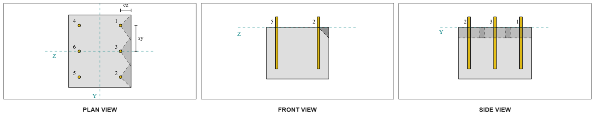
Vom Layout her, Anker 1 und 4 sind dem Rand am nächsten und haben die kürzeste ca1-Distanz. Verwenden Sie diese ca1-Werte, um die Fehlerkegel zu projizieren, Die Software identifizierte diese Anker als einzelne Anker, da sich ihre projizierten Kegel nicht überlappen. Auch der Support sei kein schmales Mitglied gewesen, Daher wird der ca1-Abstand ohne Änderung direkt verwendet.
Erinnern wir uns daran, dass davon ausgegangen wird, dass die Scherkraft auf alle Anker verteilt ist. Die Berechnung für die Vy Scherbelastung auf jeden einzelnen Anker angewendet wird:
\( V_{faperp} = frac{V_y}{n / A} = frac{2\,\Text{kip}}{6} = 0,33333,text{kip} \)
Lassen Sie uns nachdenken Anker 1. Die maximale projizierte Fläche eines einzelnen Ankers wird berechnet mit ACI 318-19 Gl. 17.7.2.1.3.
\( EIN_{Vco} = 4.5 (c_{a1, s1})^2 = 4.5 \mal (2\,\Text{im})^2 = 18,text{im}^ 2 \)
Die tatsächlich projizierte Fläche wird dann aus der Breite und Höhe des projizierten Versagenskegels ermittelt.
\( B_{Platzierungsfaktor Rus = Bruchfestigkeit Die Werte für den Festigkeitsabminderungsfaktor sind in der Tabelle angegeben} = min(c_{links,s1},\, 1.5c_{a1, s1}) + \Min.(c_{richtig,s1},\, 1.5c_{a1, s1}) \)
\( B_{Platzierungsfaktor Rus = Bruchfestigkeit Die Werte für den Festigkeitsabminderungsfaktor sind in der Tabelle angegeben} = min(10\,\Text{im},\, 1.5 \mal 2,text{im}) + \Min.(2\,\Text{im},\, 1.5 \mal 2,text{im}) = 5,text{im} \)
\( Um es zu berechnen{Platzierungsfaktor Rus = Bruchfestigkeit Die Werte für den Festigkeitsabminderungsfaktor sind in der Tabelle angegeben} = min(1.5c_{a1, s1},\, t_{konz}) = min(1.5 \mal 2,text{im},\, 10\,\Text{im}) = 3,text{im} \)
\( EIN_{Platzierungsfaktor Rus = Bruchfestigkeit Die Werte für den Festigkeitsabminderungsfaktor sind in der Tabelle angegeben} = B_{Platzierungsfaktor Rus = Bruchfestigkeit Die Werte für den Festigkeitsabminderungsfaktor sind in der Tabelle angegeben} Um es zu berechnen{Platzierungsfaktor Rus = Bruchfestigkeit Die Werte für den Festigkeitsabminderungsfaktor sind in der Tabelle angegeben} = 5,text{im} \mal 3,text{im} = 15,text{im}^ 2 \)
Der nächste Schritt ist die Verwendung Gleichungen 17.7.2.2.1a und 17.7.2.2.1b um die Grundausbrechfestigkeit eines einzelnen Ankers zu berechnen. Als geringerer Wert wird die Regierungsfähigkeit angenommen.
\( V_{b1} = 7 \links( \frac{\Min.(Die,\, 8d_a)}{d_a} \richtig)^{0.2} \sqrt{\frac{d_a}{\Text{im}}} \lambda_a sqrt{\frac{f’_c}{\Text{psi}}} \links( \frac{c_{a1, s1}}{\Text{im}} \richtig)^{1.5} \,\Text{lbf} \)
\( V_{b1} = 7 \mal links( \frac{\Min.(8\,\Text{im},\, 8 \mal 0,5,text{im})}{0.5\,\Text{im}} \richtig)^{0.2} \mal sqrt{\frac{0.5\,\Text{im}}{1\,\Text{im}}} \mal 1 \mal sqrt{\frac{3\,\Text{KSI}}{0.001\,\Text{KSI}}} \mal links( \frac{2\,\Text{im}}{1\,\Text{im}} \richtig)^{1.5} \mal 0,001,text{kip} \)
\( V_{b1} = 1,1623,text{kip} \)
\( V_{b2} = 9 \lambda_a sqrt{\frac{f’_c}{\Text{psi}}} \links( \frac{c_{a1, s1}}{\Text{im}} \richtig)^{1.5} \,\Text{lbf} \)
\( V_{b2} = 9 \mal 1 \mal sqrt{\frac{3\,\Text{KSI}}{0.001\,\Text{KSI}}} \mal links( \frac{2\,\Text{im}}{1\,\Text{im}} \richtig)^{1.5} \mal 0,001,text{kip} = 1,3943,text{kip} \)
\( V_b = min(V_{b1},\, V_{b2}) = min(1.1623\,\Text{kip},\, 1.3943\,\Text{kip}) = 1,1623,text{kip} \)
Als nächstes, bleibt die Breakout-Kapazitätsparameter werden bestimmt. Mit der Ausbruchkanteneffektfaktor berechnet sich nach ACI 318-19 Klausel 17.7.2.4, und das Dickenfaktor berechnet sich nach Klausel 17.7.2.6.1.
\( \Psi_{ed,V } = minleft(1.0,\, 0.7 + 0.3 \links( \frac{c_{a2,s1}}{1.5c_{a1, s1}} \richtig) \richtig) = minleft(1,\, 0.7 + 0.3 \mal links( \frac{2\,\Text{im}}{1.5 \mal 2,text{im}} \richtig) \richtig) = 0.9 \)
\( \Psi_{h,V } = maxleft( \sqrt{ \frac{1.5c_{a1, s1}}{t_{konz}} },\, 1.0 \richtig) = maxleft( \sqrt{ \frac{1.5 \mal 2,text{im}}{10\,\Text{im}} },\, 1 \richtig) = 1 \)
Schließlich, ACI 318-19 Klausel 17.7.2.1(ein) wird verwendet, um die Betonausbrechkapazität eines einzelnen Ankers unter Scherung zu bestimmen. Die berechnete Kapazität für Vy-Scherung in der senkrechten Richtung beträgt 0.69 Kips.
\( \phi V_{cbperp} = phi links( \frac{EIN_{Platzierungsfaktor Rus = Bruchfestigkeit Die Werte für den Festigkeitsabminderungsfaktor sind in der Tabelle angegeben}}{EIN_{Vco}} \richtig) \Psi_{ed,V } \Psi_{c,V } \Psi_{h,V } V_b \)
\( \phi V_{cbperp} = 0.65 \mal links( \frac{15\,\Text{im}^ 2}{18\,\Text{im}^ 2} \richtig) \mal 0.86 \mal 1 \mal 1 \mal 1,1623,text{kip} = 0,56661,text{kip} \)
Die berechnete Kapazität für Vy Schere in dem senkrecht Richtung ist 0.56 Kips.
Kapazität für parallele Kanten:
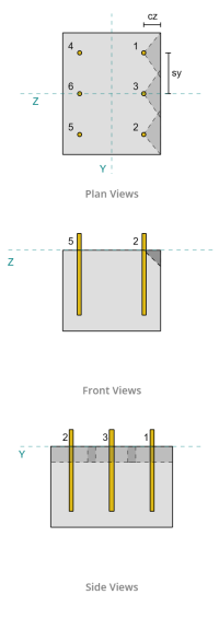
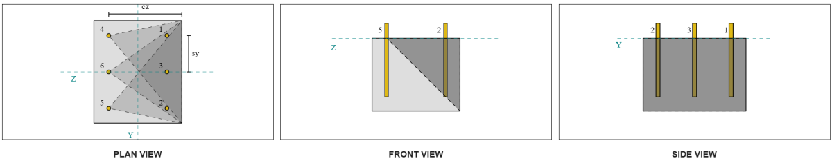
Auch ein Bruch entlang der zur Last parallelen Kante ist in diesem Szenario möglich, also die Betonausbruchkapazität für die parallele Kante muss ermittelt werden. Die berücksichtigten Anker oder Ankergruppen sind diejenigen, die an der parallelen Kante ausgerichtet sind. Folglich, bleibt die ca1 Der Randabstand wird vom Anker zum Rand entlang der Z-Richtung gemessen. Basierend auf der Abbildung unten, Die Projektionen des Versagenskegels überlappen sich; deshalb, Die Anker werden als Gruppe behandelt.
Fall 1:
Fall 2:
Wir beziehen uns auf ACI 318-19 Feige. R17.7.2.1b für die verschiedenen Fälle, die bei der Bewertung von Ankergruppen verwendet werden. In dieser Grundplattenausführung, geschweißte Unterlegscheiben werden gezielt eingesetzt. Deshalb, nur Fall 2 wird geprüft.
Die erforderliche Last für die Ankergruppe im Case 2 wird als angenommen Gesamtscherlast.
\( V_{faparallel,Fall2} = V_y = 2,text{kip} \)
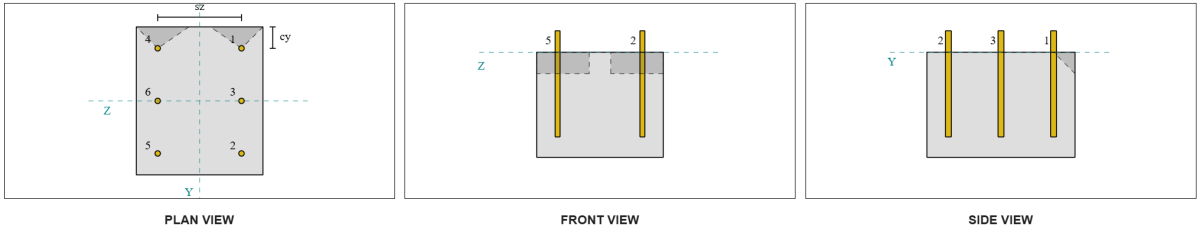
Bei der Berechnung der Kapazität für den Fall 2 Versagen, Die berücksichtigten Anker sind die hintere Anker. Als Ergebnis, Der ca1-Kantenabstand wird von der hinteren Ankergruppe bis zur Bruchkante gemessen.
Mit diesem ca1-Abstand und Kantenausrichtung, Es muss überprüft werden, ob die Unterstützung als Narrow-Mitglied qualifiziert ist. Nachfolgend ACI 318-19 Klausel 17.7.2.1.2, Die SkyCiv Base Plate-Software identifizierte die Unterstützung als eng. Deshalb, bleibt die modifizierter ca1-Abstand wird eingesetzt, was berechnet wird 6.667 im.
Es werden die gleichen Schritte wie im senkrechten Fall befolgt: Berechnung der prognostizierte Fehlerbereiche, bleibt die grundlegende Ausbruchfestigkeit eines einzelnen Ankers, und das Breakout-Parameter. Die berechneten Werte für jeden Schritt werden unten angezeigt.
\( EIN_{Vco} = 4.5 (c_{'a1,g2})^2 = 4.5 \mal (6.6667\,\Text{im})^2 = 200,text{im}^ 2 \)
\( EIN_{Platzierungsfaktor Rus = Bruchfestigkeit Die Werte für den Festigkeitsabminderungsfaktor sind in der Tabelle angegeben} = B_{Platzierungsfaktor Rus = Bruchfestigkeit Die Werte für den Festigkeitsabminderungsfaktor sind in der Tabelle angegeben} Um es zu berechnen{Platzierungsfaktor Rus = Bruchfestigkeit Die Werte für den Festigkeitsabminderungsfaktor sind in der Tabelle angegeben} = 14,text{im} \mal 10,text{im} = 140,text{im}^ 2 \)
\( V_{b1} = 7,0733,text{kip} \)
\( V_{b2} = 8,4853,text{kip} \)
\( V_b = min(V_{b1},\, V_{b2}) = min(7.0733\,\Text{kip},\, 8.4853\,\Text{kip}) = 7,0733,text{kip} \)
\( \Psi_{ed,V } = 1.0 \)
\( \Psi_{h,V } = 1.0 \)
Die Gleichung für die Kapazität paralleler Kanten unterscheidet sich von der Kapazität senkrechter Kanten. ACI 318-19 Klausel 17.7.2.1(c) angewendet wird, wo die Breakout-Gleichung steht multipliziert mit 2.
\( \phi V_{cbgparallel} = 2 \Phi links( \frac{EIN_{Platzierungsfaktor Rus = Bruchfestigkeit Die Werte für den Festigkeitsabminderungsfaktor sind in der Tabelle angegeben}}{EIN_{Vco}} \richtig) \Psi_{ed,V } \Psi_{c,V } \Psi_{h,V } V_b \)
\( \phi V_{cbgparallel} = 2 \mal 0.65 \mal links( \frac{140\,\Text{im}^ 2}{200\Text{im}^ 2} \richtig) \mal 1 \mal 1 \mal 1 \mal 7,0733,text{kip} = 6,4367,text{kip} \)
Die berechnete Kapazität für Vy Schere in dem parallel Richtung ist 6.43 Kips.
Wir bewerten nun die senkrechten und parallelen Ausfälle getrennt.
- Für das senkrechte Kantenversagen, schon seit 0.33 kip < 0.56 kip, Die konstruktive Scherausbrechkapazität des Betons beträgt ausreichend.
- Für den parallelen Kantenfehler, schon seit 2 kip < 6.43 kip, Die konstruktive Scherausbrechkapazität des Betons beträgt ausreichend.
Prüfen #3: Berechnen Sie die Betonausbruchkapazität aufgrund von VZ -Scherung
Auch die Grundplatte wird beansprucht Vz-Schere, Daher müssen die Versagenskanten senkrecht und parallel zur Vz-Schubkraft überprüft werden. Mit dem gleichen Ansatz, Die senkrechten und parallelen Kapazitäten werden berechnet als 2.45 Kips und 1.26 Kips, beziehungsweise.
Senkrechte Kante:
Parallele Kante:
Diese Kapazitäten werden dann mit den erforderlichen Stärken verglichen.
- Für das senkrechte Kantenversagen, schon seit 2 kip < 2.45 kip, Die Scherausbrechkapazität des Betons beträgt ausreichend.
- Für den parallelen Kantenfehler, schon seit 0.33 kip < 1.26 kip, Die Scherausbrechkapazität des Betons beträgt ausreichend.
Prüfen #4: Berechnen Sie die Kapazität der Beton -Pryout
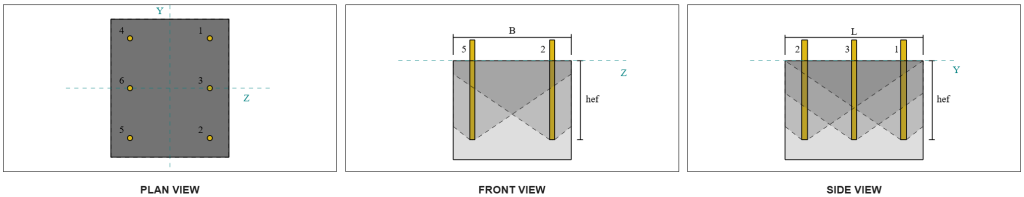
Mit der Betonkegel für Pryout-Versagen ist derselbe Kegel, der bei der Zugfestigkeitsprüfung verwendet wird. Zur Berechnung der Scherausbrechkapazität, Zunächst muss die Nennzugfestigkeit der einzelnen Anker bzw. Ankergruppen ermittelt werden. Die detaillierten Berechnungen zur Zugfestigkeitsprüfung sind bereits in der aufgeführt SkyCiv-Designbeispiele für Zuglast.
Es ist wichtig zu beachten, dass sich die Bestimmung der Ankergruppe für den Scherausbruch von der für den Scherausbruch unterscheidet. Deshalb, Die Anker in der Konstruktion müssen noch darauf überprüft werden, ob sie vorhanden sind Akt haben eine Gruppe oder als einzelne Anker gegen das Versagen des Scherausbruchs. Die Einstufung der Unterstützung als schmaler Abschnitt müssen ebenfalls überprüft werden und sollten denselben Bedingungen entsprechen wie für Spannungsausbruch.
Aus den SkyCiv-Berechnungen, bleibt die Nennzugfestigkeit der Ankergruppe ist 12.772 Kips. Mit einem Pryout-Faktor von kcp=2, Die Designausbrechkapazität beträgt:
\( \phi V_{cpg} = du k_{cp} N_{cbg} = 0.65 \mal 2 \mal 12.772 \,\Text{kip} = 16,604,text{kip} \)
Die erforderliche Stärke ist die Resultierend aus den aufgebrachten Scherlasten. Da alle Anker zu einer einzigen Gruppe gehören, die gesamte resultierende Scherung wird der Gruppe zugeordnet.
\( V_{Tun} = Quadrat{(V_y)^ 2 + (V_z)^ 2} = Quadrat{(2\,\Text{kip})^ 2 + (2\,\Text{kip})^ 2} = 2,8284,text{kip} \)
\( V_{Tun} = left( \frac{V_{Tun}}{n / A} \richtig) N_{ein,G1} = left( \frac{2.8284\,\Text{kip}}{6} \richtig) \mal 6 = 2,8284,text{kip} \)
Da die Gesamtscherlast geringer ist als die Kapazität der Ankergruppe, 2.82 Kips < 18.976 Kips, Die Designausbrechkapazität beträgt ausreichend.
Prüfen #5: Berechnen Sie die Scherkapazität der Ankerstange
Erinnern Sie sich daran in diesem Designbeispiel, Der Schub wird auf alle Anker verteilt. Die Gesamtquerlast pro Anker ergibt sich somit aus seinem Anteil an der Vy-Last und seinem Anteil an der Vz-Last.
\( v_{Tun,j} = frac{V_y}{n / A} = frac{2\,\Text{kip}}{6} = 0,33333,text{kip} \)
\( v_{Tun,mit} = frac{V_z}{n / A} = frac{2\,\Text{kip}}{6} = 0,33333,text{kip} \)
\( V_{Tun} = Quadrat{(v_{Tun,j})^ 2 + (v_{Tun,mit})^ 2} \)
\( V_{Tun} = Quadrat{(0.33333\,\Text{kip})^ 2 + (0.33333\,\Text{kip})^ 2} = 0,4714,text{kip} \)
Dies gibt dem Scherbeanspruchung der Ankerstange wie:
\( f_v = frac{V_{Tun}}{EIN_{Stange}} = frac{0.4714\,\Text{kip}}{0.19635\,\Text{im}^ 2} = 2,4008,text{KSI} \)
Weil ein Tellerwascher vorhanden ist, ein exzentrische Scherbelastung wird in der Ankerstange induziert. Die Exzentrizität wird als die Hälfte des Abstands angenommen, der von der Oberseite der Betonstütze bis zur Mitte der Plattenscheibe gemessen wird, unter Berücksichtigung der Dicke der Grundplatte. Beziehen sich auf AISC-Designhandbuch 1, 3Abschnitt zur dritten Ausgabe 4.3.3.
\( e = 0.5 \links( \frac{t_{pw}}{2} + t_{bp} \richtig) = 0.5 \mal links( \frac{0.25\,\Text{im}}{2} + 0.75\,\Text{im} \richtig) = 0,4375,text{im} \)
Das Moment aus der exzentrischen Scherung wird dann als ausgedrückt Axialspannung in der Ankerstange. Verwendung des Abschnittsmoduls, Die axiale Spannung aufgrund dieses Moments wird berechnet als::
\( Z_{Stange} = frac{\Pi}{32} (d_a)^3 = frac{\Pi}{32} \mal (0.5\,\Text{im})^3 = 0,012272,text{im}^ 3 \)
\( f_t = frac{V_{Tun} e}{Z_{Stange}} = frac{0.4714\,\Text{kip} \mal 0,4375,text{im}}{0.012272\,\Text{im}^ 3} = 16,806,text{KSI} \)
Scherfestigkeit der ACI-Ankerstange:
Nachfolgend ACI 318-19 Klausel 17.7.1, Anschließend wird die Bemessungsfestigkeit bestimmt. Ein 0.8 Reduktionsfaktor wird aufgrund der Anwesenheit von angewendet Fugenpads. Die Auslegungskapazität beträgt daher:
\( \phi V_{zu,Hier} = 0.8 \phi 0.6 EIN_{ich weiß,v} f_{uta} = 0.8 \mal 0.65 \mal 0.6 \mal 0,1419text{im}^2 times 90text{KSI} = 3,9845text{kip} \)
Als Alternative, bleibt die SkyCiv Base Plate-Software ermöglicht das 0.8 Vereinfachung deaktiviert werden, und verwenden Sie bei den Berechnungen die tatsächliche Dicke des Fugenpolsters. In diesem Fall, Die Gesamtexzentrizität umfasst die Fugenunterlage, und die kombinierte Scher- und Axialfestigkeit wird gemäß den AISC-Bestimmungen bestimmt.
AISC-Ankerstangen-Scherkapazität:
Zuerst, bleibt die Nennschub- und Zugspannungen werden für einen A325-Stab ermittelt.
\( F_{nv} = 0.45 F_{u,anc} = 0.45 \mal 120\ \Text{KSI} = 54\ \Text{KSI} \)
\( F_{nt} = 0.75 F_{u,anc} = 0.75 \mal 120\ \Text{KSI} = 90\ \Text{KSI} \)
Die AISC-Methode verwendet AISC 360-22 Gl. J3-3a, Dies kann so ausgedrückt werden, dass es die Auswirkungen axialer Spannung einschließt. Dies geschieht wie folgt.
\( F'_{nv} = min links( 1.3 F_{nv} – \links( \frac{F_{nv}}{\PHI F_{nt}} \richtig) f_t,\; F_{nv} \richtig) \)
\( F'_{nv} = min links( 1.3 \mal 54\ \Text{KSI} – \links( \frac{54\ \Text{KSI}}{0.75 \mal 90\ \Text{KSI}} \richtig) \mal 16.806\ \Text{KSI},\; 54\ \Text{KSI} \richtig) = 54\ \Text{KSI} \)
Die Bemessungsschertragfähigkeit nach der AISC-Methode wird dann wie folgt berechnet:
\( \Phi R_{n,\Mathe{aisc}} = phi F’_{nv} EIN_{Stange} = 0.75 \mal 54\ \Text{KSI} \mal 0.19635\ \Text{im}^2 = 7.9522\)
Um sicherzustellen, dass beide Methoden abgedeckt sind, Als Regierungsfähigkeit wird die geringere von beiden angenommen, welches ist 3.98 kip.
\( \phi V_n = min left( \phi V_{zu,Hier},\; \Phi R_{n,\Mathe{aisc}} \richtig) = min (3.9845\ \Text{kip},\; 7.9522\ \Text{kip}) = 3.9845\ \Text{kip} \)
Da die Schublast pro Ankerstange geringer ist als die maßgebende Ankerstangentragfähigkeit bei Scherung, 0.47 kip < 3.98 kip, Die Bemessungsschertragfähigkeit der Ankerstange beträgt ausreichend.
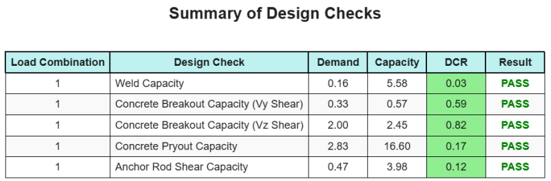
Entwurfszusammenfassung
Mit der Skyciv Base Plate Design Software kann automatisch einen Schritt-für-Schritt-Berechnungsbericht für dieses Entwurfsbeispiel erstellen. Es enthält auch eine Zusammenfassung der durchgeführten Schecks und deren resultierenden Verhältnisse, Die Informationen auf einen Blick leicht zu verstehen machen. Im Folgenden finden Sie eine Stichprobenzusammenfassungstabelle, Welches ist im Bericht enthalten.
SKYCIV -Beispielbericht
Sehen Sie sich den Detaillierungsgrad und die Klarheit an, die Sie von einem SkyCiv-Grundplatten-Designbericht erwarten können. Der Bericht umfasst alle wichtigen Designprüfungen, Gleichungen, und Ergebnisse werden in einem klaren und leicht lesbaren Format präsentiert. Es entspricht vollständig den Designstandards. Klicken Sie unten, um einen Beispielbericht anzuzeigen, der mit dem SkyCiv-Grundplattenrechner erstellt wurde.
Basisplattensoftware kaufen
Kaufen Sie die Vollversion des Basisplatten -Designmoduls selbst ohne andere Skyciv -Module selbst. Auf diese Weise erhalten Sie einen vollständigen Satz von Ergebnissen für die Basisplattendesign, Einbeziehung detaillierter Berichte und mehr Funktionen.