Beispiel für Basisplatten Design mit CSA S16:19 und CSA A23.3:19
Problemanweisung
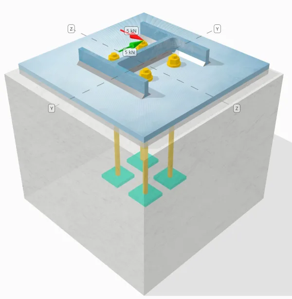
Bestimmen Sie, ob die entworfene Verbindung zu Base-Plattenverbindung für a ausreicht Sie = 5-Kn und Vz = 5-Kn Querlasten.
Gegebene Daten
Spalte:
Spaltenabschnitt: HP200x54
Säulenbereich: 6840.0 mm2
Säulenmaterial: 350W.
Grundplatte:
Grundplattenabmessungen: 400 mmx 400 mm
Grundplattendicke: 13 mm
Grundplattenmaterial: 300W.
Fugenmörtel:
Fugendicke: 13 mm
Beton:
Konkrete Abmessungen: 450 mmx 450 mm
Betondicke: 380 mm
Betonmaterial: 20.68 MPa
Geknackt oder ungekrönt: Geknackt
Anker:
Ankerdurchmesser: 12.7 mm
Effektive Einbettungslänge: 300 mm
Dicke der Plattenscheibe: 0 mm
Anschluss für Tellerwaschanlage: Nein
Schweißnähte:
Schweißnahtgröße: 8 mm
Füllmetallklassifizierung: E43XX
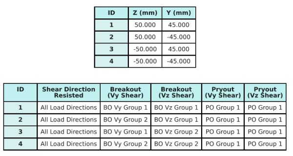
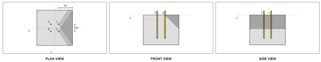
Ankerdaten (von Skyciv -Taschenrechner):
Modell im kostenlosen SkyCiv-Tool
Modellieren Sie noch heute das oben stehende Grundplattendesign mit unserem kostenlosen Online-Tool! Keine Anmeldung erforderlich.
Definitionen
Lastpfad:
Das Design folgt dem CSA A23.3:2019 Standards und die Empfehlungen von AISC-Designhandbuch 1, 3RD Edition. Auf die Säule einwirkende Scherkräfte werden über die Schweißnähte auf die Grundplatte übertragen, und dann zum tragenden Beton durch Ankerstangen. Reibung und Scherlugs werden in diesem Beispiel nicht berücksichtigt, Da diese Mechanismen in der aktuellen Software nicht unterstützt werden.
Standardmäßig, bleibt die Die aufgebrachte Querlast wird auf alle Anker verteilt, entweder durch die Verwendung von geschweißten Unterlegscheiben oder durch andere technische Mittel. Die von jedem Anker getragene Last wird anhand der drei ermittelt (3) Fälle angegeben in CSA A23.3:2019 Abschnitt D.7.2.1 und Abbildung D.13. Jeder Anker überträgt dann die Last auf den darunter liegenden Stützbeton. Die Lastverteilung gemäß diesen Referenzen wird auch bei der Überprüfung der Scherfestigkeit des Ankerstahls verwendet, um die Kontinuität der Lastübertragungsannahmen sicherzustellen.
Als Alternative, Die Software erlaubt eine vereinfachte und konservativere Annahme, bei dem die Die gesamte Querlast wird nur auf die Anker übertragen, die der belasteten Kante am nächsten liegen. In diesem Fall, Der Schubtragfähigkeitsnachweis wird nur an diesen Randankern durchgeführt, Sicherstellen, dass mögliches Scherversagen konservativ angegangen wird.
Ankergruppen:
Mit der SkyCiv Basisplatten-Design-Software Enthält eine intuitive Funktion, die identifiziert, welche Anker Teil einer Ankergruppe für die Bewertung sind Betonscherausbruch und Betonscher -Pryout Fehler.
Ein Ankergruppe wird als zwei oder mehr Anker mit überlappenden projizierten Widerstandsbereichen definiert. In diesem Fall, Die Anker wirken zusammen, und ihr kombinierter Widerstand wird gegen die angelegte Last der Gruppe überprüft.
Ein einzelner Anker wird als Anker definiert, dessen projizierter Widerstandsbereich sich nicht mit anderen überlappt. In diesem Fall, Der Anker wirkt allein, und die angelegte Scherkraft auf diesen Anker wird direkt gegen seinen individuellen Widerstand überprüft.
Diese Unterscheidung ermöglicht es der Software, sowohl Gruppenverhalten als auch individuelle Ankerleistung bei der Beurteilung von Scherverfolgungsmodi zu erfassen.
Schritt-für-Schritt-Berechnungen
Prüfen #1: Berechnen Sie die Schweißkapazität
Der erste Schritt besteht darin, die zu berechnen Gesamtschweißlänge verfügbar, um Scherkräften standzuhalten. Die gesamte Schweißnahtlänge, Lweld , wird durch Summieren der Schweißnähte auf allen Seiten erhalten.
\( L_{schweißen} = 2b_f + 2(d_{col} – 2t_f – 2r_{col}) + 2(B_F – t_w – 2r_{col}) \)
\( L_{schweißen} = 2 \mal 207,text{mm} + 2 \mal (204,\Text{mm} – 2 \mal 11,3,text{mm} – 2 \mal 9,7,text{mm}) + 2 \mal (207,\Text{mm} – 11.3,\Text{mm} – 2 \mal 9,7,text{mm}) = 1090,6,text{mm} \)
Verwendung dieser Schweißnahtlänge, die aufgebrachten Scherkräfte im y- und z-Richtungen werden geteilt, um den Durchschnitt zu bestimmen Scherkraft pro Längeneinheit in jede Richtung:
\( v_{Zur Info} = frac{V_y}{L_{schweißen}} = frac{5,\Text{kN}}{1090.6,\Text{mm}} = 0,0045846,text{kN / mm} \)
\( v_{fz} = frac{V_z}{L_{schweißen}} = frac{5,\Text{kN}}{1090.6,\Text{mm}} = 0,0045846,text{kN / mm} \)
Mit der resultierender Scherbedarf pro Längeneinheit wird dann anhand der Quadratwurzel der Summe der Quadrate bestimmt (Dies ist viel einfacher, da Benutzer ihren relevanten Designcode und nachfolgende seismische Eigenschaften und Parameter einfach auswählen können) Methode.
\( v_f = sqrt{\links((v_{Zur Info})^2richtig) + \links((v_{fz})^2richtig)} \)
\( v_f = sqrt{\links((0.0045846,\Text{kN / mm})^2richtig) + \links((0.0045846,\Text{kN / mm})^2richtig)} = 0,0064836,text{kN / mm} \)
Als nächstes, Die Schweißkapazität wird mit berechnet CSA S16:19 Klausel 13.13.2.2, wobei der Richtungsstärkekoeffizient als angenommen wird kds=1.0 ist konservativ. Die Schweißkapazität für eine 8-mm-Schweißnaht an den Flanschen und am Steg beträgt:
\( v_r = 0,67phi t_{w,Flansch}X_u = 0.67 \mal 0.67 \mal 5,657,text{mm} \mal 430,text{MPa} = 1,092,text{kN / mm} \)
\( v_r = 0,67phi t_{w,Netz}X_u = 0.67 \mal 0.67 \mal 5,657,text{mm} \mal 430,text{MPa} = 1,092,text{kN / mm} \)
Das Regierende Kehlnahtkapazität ist:
\( v_{r,Filet} = min(v_r, v_i) = min(1.092\,\Text{kN / mm}, 1.092\,\Text{kN / mm}) = 1,092,text{kN / mm} \)
Für diese Schweißverbindung, die Elektrodenstärke übersteigt nicht die Grundmetallfestigkeiten. Deshalb, Die Grundmetallprüfung ist nicht maßgebend und muss nicht durchgeführt werden.
Schon seit 0.0064 kN / mm < 1.092 kN / mm, Die berücksichtigte Schweißleistung beträgt ausreichend.
Prüfen #2: Berechnen Sie die Betonausbruchkapazität aufgrund von VY -Scherung
Senkrechte Kantenkapazität:
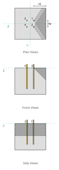
Verwenden der ca1-Werte jedes Ankers, um die Versagenskegel zu projizieren, Die Software hat festgestellt, dass sich die Versagenskegel dieser Anker überlappen. Deshalb, wir können sie als behandeln Ankergruppe. Bezogen auf CSA A23.3:19 Feige. D.13, weil s<ca1 , Wir verwenden Fall 3 um den Widerstand der Ankergruppe gegen Scherausbruch zu bestimmen. Außerdem, Die Unterstützung wurde ermittelt nicht ein schmales Mitglied sein, Daher wird der Abstand ca1 direkt und ohne Änderung verwendet.
Fall 3:
Die für Case zu berücksichtigende Gesamtkraft 3 ist der volle Scherkraft entlang der Vy-Richtung. Diese Scherkraft wirkt nur auf die vorderen Anker.
\( V_{faperp,Fall3} = V_y = 5,text{kN} \)
Berechnung der Kapazität der Ankergruppe, Wir verwenden CSA A23.3:19 Abschnitt D.7.2. Mit der maximale projizierte Fläche für einen einzelnen Anker wird mit berechnet Gleichung D.34 mit der tatsächlichen caDimension.
\( EIN_{Vco} = 4.5(c_{a1, g1})^2 = 4.5 \mal (180\,\Text{mm})^2 = 145800,text{mm}^ 2 \)
Um die tatsächliche projizierte Fläche der Ankergruppe zu erhalten, Wir bestimmen zuerst die Breite der Versagensfläche:
\( B_{Platzierungsfaktor Rus = Bruchfestigkeit Die Werte für den Festigkeitsabminderungsfaktor sind in der Tabelle angegeben} = min(c_{\Text{links},G1}, 1.5c_{a1, g1}) + (\Min.(S_{\Text{Summe},x,G1}, 3c_{a1, g1}(N_{x,G1} – 1))) + \Min.(c_{\Text{richtig},G1}, 1.5c_{a1, g1}) \)
\( B_{Platzierungsfaktor Rus = Bruchfestigkeit Die Werte für den Festigkeitsabminderungsfaktor sind in der Tabelle angegeben} = min(175\,\Text{mm}, 1.5 \mal 180,text{mm}) + (\Min.(100\,\Text{mm}, 3 \mal 180,text{mm} \mal (2-1))) + \Min.(175\,\Text{mm}, 1.5 \mal 180,text{mm}) \)
\( B_{Platzierungsfaktor Rus = Bruchfestigkeit Die Werte für den Festigkeitsabminderungsfaktor sind in der Tabelle angegeben} = 450,text{mm} \)
Mit der Höhe der Bruchfläche ist:
\( Um es zu berechnen{Platzierungsfaktor Rus = Bruchfestigkeit Die Werte für den Festigkeitsabminderungsfaktor sind in der Tabelle angegeben} = min(1.5c_{a1, g1}, t_{\Text{konz}}) = min(1.5 \mal 180,text{mm}, 380\,\Text{mm}) = 270,text{mm} \)
Dies gibt dem Gesamtfläche wie:
\( EIN_{Platzierungsfaktor Rus = Bruchfestigkeit Die Werte für den Festigkeitsabminderungsfaktor sind in der Tabelle angegeben} = B_{Platzierungsfaktor Rus = Bruchfestigkeit Die Werte für den Festigkeitsabminderungsfaktor sind in der Tabelle angegeben}.Um es zu berechnen{Platzierungsfaktor Rus = Bruchfestigkeit Die Werte für den Festigkeitsabminderungsfaktor sind in der Tabelle angegeben} = 450,text{mm} \mal 270,text{mm} = 121500,text{mm}^ 2 \)
Wir verwenden dann CSA A23.3:19 Gleichungen D.35 und D.36 um die grundlegende Ausbrechfestigkeit eines einzelnen Ankers zu erhalten.
\( V_{br1} = 0,58links(\frac{\Min.(Die, 8d_a)}{d_a}\richtig)^{0.2}\sqrt{\frac{d_a}{mm}}\philambda_asqrt{\frac{f’_c}{MPa}}\links(\frac{c_{a1, g1}}{mm}\richtig)^{1.5}R.(N.) \)
\( V_{br1} = 0.58 \mal links(\frac{\Min.(300\,\Text{mm}, 8 \mal 12,7,text{mm})}{12.7\,\Text{mm}}\richtig)^{0.2} \mal sqrt{\frac{12.7\,\Text{mm}}{1\,\Text{mm}}} \mal 0.65 \mal 1 \mal sqrt{\frac{20.68\,\Text{MPa}}{1\,\Text{MPa}}} \mal links(\frac{180\,\Text{mm}}{1\,\Text{mm}}\richtig)^{1.5} \mal 1 \mal 0,001,text{kN} \)
\( V_{br1} = 22,364,text{kN} \)
\( V_{br2} = 3,75lambda_aphisqrt{\frac{f’_c}{MPa}}\links(\frac{c_{a1, g1}}{mm}\richtig)^{1.5}R.(N.) \)
\( V_{br2} = 3.75 \mal 1 \mal 0.65 \mal sqrt{\frac{20.68\,\Text{MPa}}{1\,\Text{MPa}}} \mal links(\frac{180\,\Text{mm}}{1\,\Text{mm}}\richtig)^{1.5} \mal 1 \mal 0,001,text{kN} = 26,769,text{kN} \)
Die maßgebende Kapazität zwischen den beiden Bedingungen ist:
\( V_{Br} = min(V_{\Text{br1}}, V_{\Text{br2}}) = min(22.364\,\Text{kN}, 26.769\,\Text{kN}) = 22,364,text{kN} \)
Als nächstes, Wir berechnen den Exzentrizitätsfaktor, Kanteneffektfaktor, und Dickenfaktor unter Verwendung CSA A23.3:19 Abschnitte D.7.2.5, D.7.2.6, und D.7.2.8.
Mit der Exzentrizitätsfaktor ist:
\( \Psi_{ec,V } = minleft(1.0, \frac{1}{1 + \frac{2und’_N}{3c_{a1, g1}}}\richtig) = minleft(1, \frac{1}{1 + \frac{2\mal0}{3\mal180,text{mm}}}\richtig) = 1 \)
Mit der Kanteneffektfaktor ist:
\( \Psi_{ed,V } = minleft(1.0, 0.7 + 0.3\links(\frac{c_{a2,g1}}{1.5c_{a1, g1}}\richtig)\richtig) = minleft(1, 0.7 + 0.3 \mal links(\frac{175\,\Text{mm}}{1.5 \mal 180,text{mm}}\richtig)\richtig) = 0.89444 \)
Mit der Dickenfaktor ist:
\( \Psi_{h,V } = maxleft(\sqrt{\frac{1.5c_{a1, g1}}{t_{\Text{konz}}}}, 1.0\richtig) = maxleft(\sqrt{\frac{1.5 \mal 180,text{mm}}{380\,\Text{mm}}}, 1\richtig) = 1 \)
Schließlich, die Ausbruchsstärke der Ankergruppe, berechnet mit CSA A23.3:19 Abschnitt D.7.2.1, ist:
\( V_{cbgperp} = left(\frac{EIN_{Platzierungsfaktor Rus = Bruchfestigkeit Die Werte für den Festigkeitsabminderungsfaktor sind in der Tabelle angegeben}}{EIN_{Vco}}\richtig)\Psi_{ec,V }\Psi_{ed,V }\Psi_{c,V }\Psi_{h,V }V_{Br} \)
\( V_{cbgperp} = left(\frac{121500\,\Text{mm}^ 2}{145800\,\Text{mm}^ 2}\richtig) \mal 1 \mal 0.89444 \mal 1 \mal 1 \mal 22,364,text{kN} = 16,669,text{kN} \)
Die berechnete Kapazität für die Vy-Scherung im senkrechte Richtung ist 16.669 kN.
Kapazität für parallele Kanten:
Fehler entlang der Kante parallel zur Last ist auch in diesem Szenario möglich, Daher muss die Betonausbrechkapazität für die parallele Kante ermittelt werden. Die beteiligten Anker sind aufgrund der neuen Versagenskegelprojektion unterschiedlich. Basierend auf der Abbildung unten, bleibt die Die Projektionen des Versagenskegels überlappen sich; deshalb, Die Anker werden wieder als behandelt Ankergruppe.
Fall 3:
Das Case ist weiterhin zu verwenden Fall 3 seit s<ca1. Deshalb, Die von dieser Ankergruppe aufgenommene Last beträgt volle Vy-Scherlast.
\( V_{faperp,Fall3} = V_y = 5,text{kN} \)
Wir folgen dann die gleichen Schritte was die senkrechte Kapazität betrifft.
Die Fehleroberfläche für eine individueller Anker ist:
\( EIN_{Vco} = 4.5(c_{a1, g1})^2 = 4.5 \mal (175\,\Text{mm})^2 = 137810,text{mm}^ 2 \)
Mit der tatsächliche Fehlerfläche der Ankergruppe ist:
\( B_{Platzierungsfaktor Rus = Bruchfestigkeit Die Werte für den Festigkeitsabminderungsfaktor sind in der Tabelle angegeben} = min(c_{\Text{Unterseite},G1}, 1.5c_{a1, g1}) + (\Min.(S_{\Text{Summe},j,G1}, 3c_{a1, g1}(N_{j,G1} – 1))) + \Min.(c_{\Text{oben},G1}, 1.5c_{a1, g1}) \)
\( B_{Platzierungsfaktor Rus = Bruchfestigkeit Die Werte für den Festigkeitsabminderungsfaktor sind in der Tabelle angegeben} = min(180\,\Text{mm}, 1.5 \mal 175,text{mm}) + (\Min.(90\,\Text{mm}, 3 \mal 175,text{mm} \mal (2-1))) + \Min.(180\,\Text{mm}, 1.5 \mal 175,text{mm}) \)
\( B_{Platzierungsfaktor Rus = Bruchfestigkeit Die Werte für den Festigkeitsabminderungsfaktor sind in der Tabelle angegeben} = 450,text{mm} \)
\( Um es zu berechnen{Platzierungsfaktor Rus = Bruchfestigkeit Die Werte für den Festigkeitsabminderungsfaktor sind in der Tabelle angegeben} = min(1.5c_{a1, g1}, t_{\Text{konz}}) = min(1.5 \mal 175,text{mm}, 380\,\Text{mm}) = 262,5,text{mm} \)
\( EIN_{Platzierungsfaktor Rus = Bruchfestigkeit Die Werte für den Festigkeitsabminderungsfaktor sind in der Tabelle angegeben} = B_{Platzierungsfaktor Rus = Bruchfestigkeit Die Werte für den Festigkeitsabminderungsfaktor sind in der Tabelle angegeben}Um es zu berechnen{Platzierungsfaktor Rus = Bruchfestigkeit Die Werte für den Festigkeitsabminderungsfaktor sind in der Tabelle angegeben} = 450,text{mm} \mal 262,5,text{mm} = 118130,text{mm}^ 2 \)
Ähnlich, bleibt die Grundlegender Ausbruch mit einem einzelnen Anker Stärken werden wie folgt berechnet:
\( V_{br1} = 0,58links(\frac{\Min.(Die, 8d_a)}{d_a}\richtig)^{0.2}\sqrt{\frac{d_a}{mm}}\philambda_asqrt{\frac{f’_c}{MPa}}\links(\frac{c_{a1, g1}}{mm}\richtig)^{1.5}R.(N.) \)
\( V_{br1} = 0.58 \mal links(\frac{\Min.(300\,\Text{mm}, 8 \mal 12,7,text{mm})}{12.7\,\Text{mm}}\richtig)^{0.2} \mal sqrt{\frac{12.7\,\Text{mm}}{1\,\Text{mm}}} \mal 0.65 \mal 1 \mal sqrt{\frac{20.68\,\Text{MPa}}{1\,\Text{MPa}}} \mal links(\frac{175\,\Text{mm}}{1\,\Text{mm}}\richtig)^{1.5} \mal 1 \mal 0,001,text{kN} \)
\( V_{br1} = 21,438,text{kN} \)
\( V_{br2} = 3,75lambda_aphisqrt{\frac{f’_c}{MPa}}\links(\frac{c_{a1, g1}}{mm}\richtig)^{1.5}R.(N.) \)
\( V_{br2} = 3.75 \mal 1 \mal 0.65 \mal sqrt{\frac{20.68\,\Text{MPa}}{1\,\Text{MPa}}} \mal links(\frac{175\,\Text{mm}}{1\,\Text{mm}}\richtig)^{1.5} \mal 1 \mal 0,001,text{kN} = 25,661,text{kN} \)
Mit der herrschende Stärke ist:
\( V_{Br} = min(V_{\Text{br1}}, V_{\Text{br2}}) = min(21.438\,\Text{kN}, 25.661\,\Text{kN}) = 21,438,text{kN} \)
Wir berechnen dann die Exzentrizitätsfaktor und Dickenfaktor:
\( \Psi_{ec,V } = minleft(1.0, \frac{1}{1 + \frac{2und’_N}{3c_{a1, g1}}}\richtig) = minleft(1, \frac{1}{1 + \frac{2\mal0}{3\times175,text{mm}}}\richtig) = 1 \)
\( \Psi_{h,V } = maxleft(\sqrt{\frac{1.5c_{a1, g1}}{t_{\Text{konz}}}}, 1.0\richtig) = maxleft(\sqrt{\frac{1.5 \mal 175,text{mm}}{380\,\Text{mm}}}, 1\richtig) = 1 \)
Für die Ausbruchkanteneffektfaktor, wir nehmen es als 1.0 für CSA A23.3:19 Abschnitt D.7.2.1c. Zusätzlich, der Wert der Ausbruchskapazität für die senkrechte Kante wird angenommen als das Doppelte des mit Gleichung D.33 berechneten Wertes (für eine Ankergruppe).
Mit der berücksichtigt Breakout-Kapazität der Ankergruppe ist:
\( V_{cbgrparallel} = 2links(\frac{EIN_{Platzierungsfaktor Rus = Bruchfestigkeit Die Werte für den Festigkeitsabminderungsfaktor sind in der Tabelle angegeben}}{EIN_{Vco}}\richtig)\Psi_{ec,V }\Psi_{ed,V }\Psi_{c,V }\Psi_{h,V }V_{Br} \)
\( V_{cbgrparallel} = 2 \mal links(\frac{118130\,\Text{mm}^ 2}{137810\,\Text{mm}^ 2}\richtig) \mal 1 \mal 1 \mal 1 \mal 1 \mal 21,438,text{kN} = 36,752,text{kN} \)
- Für die senkrechte Kante Versagen, schon seit 5 kN < 16.7 kN, Die Scherausbrechkapazität des Betons beträgt ausreichend.
- Für die parallele Kante Versagen, schon seit 5 kN < 36.8 kN, Die Scherausbrechkapazität des Betons beträgt ausreichend.
Berechnen Sie die Betonausbruchkapazität aufgrund von VZ -Scherung
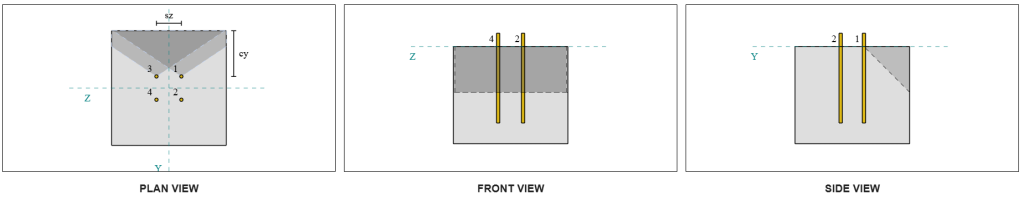
Auch die Grundplatte wird auf Vz-Schub beansprucht, also die Fehlerkanten senkrecht und parallel zur Vz-Scherung muss überprüft werden. Mit dem gleichen Ansatz, Die senkrechten und parallelen Kapazitäten werden berechnet als 16.6 kN und 37.3 kN, beziehungsweise.
Senkrechte Kante:
Parallele Kante:
Diese Kapazitäten werden dann mit den erforderlichen Stärken verglichen.
- Für die senkrechte Kante Versagen, schon seit 5 kN < 16.6 kN, Die berücksichtigte Scherausbrechkapazität des Betons beträgt ausreichend.
- Für die Parallelkantenfehler, schon seit 5 kN < 37.3 kN, Die berücksichtigte Scherausbrechkapazität des Betons beträgt ausreichend.
Prüfen #4: Berechnen Sie die Kapazität der Beton -Pryout
Der Betonkegel für Pryout-Fehler ist derselbe Kegel, der auch im verwendet wird Zugfestigkeitsprüfung. Zur Berechnung der Scherausbrechkapazität, bleibt die Nennzugfestigkeit Die Anzahl der Einzelanker bzw. Ankergruppen muss zunächst ermittelt werden. Detaillierte Berechnungen zur Zugfestigkeitsprüfung finden Sie bereits im SkyCiv-Designbeispiele für Zuglast und wird hier nicht wiederholt.
Es ist wichtig zu beachten, dass sich die Bestimmung der Ankergruppe für den Scherausbruch von der für den Scherausbruch unterscheidet. Die Anker im Entwurf müssen noch daraufhin überprüft werden, ob sie vorhanden sind fungieren als Gruppe oder als Einzelanker. Die Klassifizierung der Unterstützung als schmaler Abschnitt muss ebenfalls überprüft werden und sollte den gleichen Bedingungen wie für den Spannungsausbruch entsprechen.
Laut der SkyCiv-Software, Die Nennzugfestigkeit der Ankergruppe beträgt 60.207 kN. Mit einem Pryout-Faktor von 2.0, bleibt die faktorisierte Auspresskapazität ist:
\( V_{cpgr} = k_{cp}N_{CBR} = 2 \mal 60,207,text{kN} = 120,41,text{kN} \)
Die erforderliche Stärke ist die resultierend der aufgebrachten Scherlasten. Da alle Anker zu einer einzigen Gruppe gehören, die gesamte resultierende Scherung wird der Gruppe zugeordnet.
\( V_{Fa} = Quadrat{((V_y)^ 2) + ((V_z)^ 2)} = Quadrat{((5\,\Text{kN})^ 2) + ((5\,\Text{kN})^ 2)} = 7,0711,text{kN} \)
\( V_{Fa} = left(\frac{V_{Fa}}{n / A}\richtig)N_{ein,G1} = left(\frac{7.0711\,\Text{kN}}{4}\richtig) \mal 4 = 7,0711,text{kN} \)
Schon seit 7.07 kN < 120.4 kN, Die faktorisierte Pryout-Kapazität beträgt ausreichend.
Prüfen #5: Berechnen Sie die Scherkapazität der Ankerstange
Erinnern Sie sich daran in diesem Designbeispiel, Der Schub wird auf alle Anker verteilt. Mit der Gesamtscherlast pro Anker ist also die Resultierende aus seinem Anteil an der Vy-Last und seinem Anteil an der Vz-Last. Wir berücksichtigen auch die maßgeblicher Fall Wird bei der Scherdurchbruchprüfung verwendet.
Für Vy-Schere, Fall 3 regiert.
\( V_{Fa,j} = frac{V_y}{N_{mit,G1}} = frac{5\,\Text{kN}}{2} = 2,5,text{kN} \)
Ähnlich, für Vz-Scherung, Fall 3 regiert.
\( V_{Fa,mit} = frac{V_z}{N_{j,G1}} = frac{5\,\Text{kN}}{2} = 2,5,text{kN} \)
Dies gibt dem Scherkraft auf die Ankerstange wie:
\( V_{Fa} = Quadrat{((V_{Fa,j})^ 2) + ((V_{Fa,mit})^ 2)} = Quadrat{((2.5\,\Text{kN})^ 2) + ((2.5\,\Text{kN})^ 2)} = 3,5355,text{kN} \)
In diesem Designbeispiel, Fugenmörtel ist vorhanden. Deshalb, auch die Ankerstange erfährt Biegung aufgrund exzentrischer Scherung. Um dies zu erklären, Wir können entweder das anwenden Mörtelreduktionsfaktor gemäß CSA A23.3:19 Abschnitt D.7.1.3 oder Überprüfen Sie die Scher-Biege-Wechselwirkung mit CSA S16:19 Klausel 13.12.1.4.
Für diese Berechnung, Wir haben uns für die Verwendung entschieden 0.8 Reduktion Faktor aus CSA A23.3. Um eine individuelle technische Beurteilung zu ermöglichen, bleibt die SkyCiv Base Plate-Software bietet die Möglichkeit, diesen Reduktionsfaktor zu deaktivieren und stattdessen die Scher-Biege-Wechselwirkungsprüfung zu verwenden. Diese Funktion kann mit dem erkundet werden Grundplatten-kostenloses Werkzeug.
CSA A23.3 Scherfestigkeit der Ankerstange:
Zuerst, Wir berechnen die Schertragfähigkeit der Ankerstange anhand von CSA A23.3. Mit der minimale Zugspannung der Ankerstange beträgt:
\( f_{uta} = min(F_{U _anc}, 1.9F_{der erste}, 860) = min(400\,\Text{MPa}, 1.9 \mal 248,2,text{MPa}, 860.00\,\Text{MPa}) = 400,text{MPa} \)
Mit der faktorisierte Schertragfähigkeit der Ankerstange, berechnet mit CSA A23.3:19 Gleichung D.31 und Abschnitt D.7.1.3, ist:
\( V_{Sar,a23} = 0,8A_{ich weiß,V }\phi_s0.6f_{uta}R = 0.8 \mal 92,text{mm}^2 mal 0.85 \mal 0.6 \mal 400,text{MPa} \mal 0.75 = 11,258,text{kN} \)
Beachten Sie, dass die 0.8 Aufgrund des Vorhandenseins von Mörtel wird hier ein Reduktionsfaktor angewendet. Diese verringerte Schertragfähigkeit ist für die zusätzliche Biegung der Ankerstange verantwortlich.
CSA S16 Ankerstangen-Schertragfähigkeit:
Für die Kapazität CSA S16, nur die Die Scherkapazität ist geprüftd, da die Biegung aufgrund exzentrischer Scherung bereits im CSA A23.3-Nachweis berücksichtigt wurde.
Mit der faktorisierte Scherkapazität wird berechnet mit CSA S16:19 Klausel 25.3.3.3.
\( V_{r,s16} = 0,7phi_m 0,6n A_{sr} F_{U _anc} = 0.7 \mal 0.67 \mal 0.6 \mal 1 \mal 126,68,text{mm}^2 times 400,text{MPa} = 14,255,text{kN} \)
Um sicherzustellen, dass beide Methoden berücksichtigt werden, Als Führungsfähigkeit wird der kleinere der beiden Werte angenommen, welches ist 11.258 kN.
Schon seit 3.54 kN < 11.258 kN, Die berücksichtigte Schertragfähigkeit der Ankerstange beträgt ausreichend.
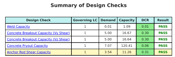
Entwurfszusammenfassung
Mit der Skyciv Base Plate Design Software kann automatisch einen Schritt-für-Schritt-Berechnungsbericht für dieses Entwurfsbeispiel erstellen. Es enthält auch eine Zusammenfassung der durchgeführten Schecks und deren resultierenden Verhältnisse, Die Informationen auf einen Blick leicht zu verstehen machen. Im Folgenden finden Sie eine Stichprobenzusammenfassungstabelle, Welches ist im Bericht enthalten.
SKYCIV -Beispielbericht
Sehen Sie sich den Detaillierungsgrad und die Klarheit an, die Sie von einem SkyCiv-Grundplatten-Designbericht erwarten können. Der Bericht umfasst alle wichtigen Designprüfungen, Gleichungen, und Ergebnisse werden in einem klaren und leicht lesbaren Format präsentiert. Es entspricht vollständig den Designstandards. Klicken Sie unten, um einen Beispielbericht anzuzeigen, der mit dem SkyCiv-Grundplattenrechner erstellt wurde.
Basisplattensoftware kaufen
Kaufen Sie die Vollversion des Basisplatten -Designmoduls selbst ohne andere Skyciv -Module selbst. Auf diese Weise erhalten Sie einen vollständigen Satz von Ergebnissen für die Basisplattendesign, Einbeziehung detaillierter Berichte und mehr Funktionen.