Basisplatten -Design -Beispiel mit eN 1993-1-8:2005, IM 1993-1-1:2005, IM 1992-1-1:2004, und EN 1992-4:2018.
Problemanweisung
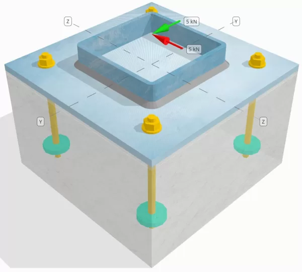
Bestimmen Sie, ob die entworfene Verbindung zu Base-Plattenverbindung für a ausreicht Sie = 5-Kn und Vz = 5-Kn Querlasten.
Gegebene Daten
Spalte:
Spaltenabschnitt: Shs 180x180x8
Säulenbereich: 5440 mm2
Säulenmaterial: S235
Grundplatte:
Grundplattenabmessungen: 350 mmx 350 mm
Grundplattendicke: 12 mm
Grundplattenmaterial: S235
Fugenmörtel:
Fugenmörtel Dicke: 6 mm
Fugenmaterial: ≥ 30 MPa
Beton:
Konkrete Abmessungen: 350 mmx 350 mm
Betondicke: 350 mm
Betonmaterial: C25/30
Geknackt oder ungekrönt: Geknackt
Anker:
Ankerdurchmesser: 12 mm
Effektive Einbettungslänge: 150 mm
Eingebetteter Plattendurchmesser: 60 mm
Dicke eingebetteter Platten: 10 mm
Ankermaterial: 8.8
Andere Informationen:
- Nicht-Counter-sunk-Anker.
- Anker mit geschnittenen Fäden.
- K7 -Faktor für Anker -Stahl -Scherversagen: 1.0
- Einschränkung des Befestigungsgrades: Keine Zurückhaltung
Schweißnähte:
Schweißtyp: Filetschweißung
Schweißbeingröße: 8mm
Füllmetallklassifizierung: E35
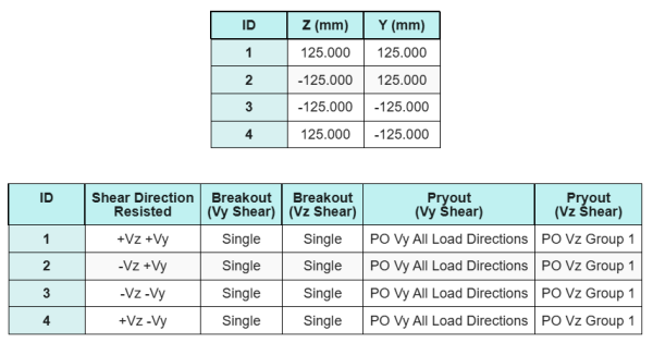
Ankerdaten (von Skyciv -Taschenrechner):
Modell im kostenlosen SkyCiv-Tool
Modellieren Sie noch heute das oben stehende Grundplattendesign mit unserem kostenlosen Online-Tool! Keine Anmeldung erforderlich.
Definitionen
Lastpfad:
Mit der SkyCiv Basisplatten-Design-Software folgt IM 1992-4:2018 Für Ankerstabdesign. Die auf die Säule angelegte Scherlasten werden durch die Schweißnähte und dann durch die Ankerstangen auf die Grundplatte übertragen. Reibung und Scherlugs werden in diesem Beispiel nicht berücksichtigt, Da diese Mechanismen in der aktuellen Software nicht unterstützt werden.
Ankergruppen:
Die Software enthält eine intuitive Funktion, die angibt, welche Anker Teil einer Ankergruppe für die Bewertung sind Betonscherausbruch und Betonscher -Pryout Fehler.
Ein Ankergruppe wird als zwei oder mehr Anker mit überlappenden projizierten Widerstandsbereichen definiert. In diesem Fall, Die Anker wirken zusammen, und ihr kombinierter Widerstand wird gegen die angelegte Last der Gruppe überprüft.
Ein einzelner Anker wird als Anker definiert, dessen projizierter Widerstandsbereich sich nicht mit anderen überlappt. In diesem Fall, Der Anker wirkt allein, und die angelegte Scherkraft auf diesen Anker wird direkt gegen seinen individuellen Widerstand überprüft.
Diese Unterscheidung ermöglicht es der Software, sowohl Gruppenverhalten als auch individuelle Ankerleistung bei der Beurteilung von Scherverfolgungsmodi zu erfassen.
Schritt-für-Schritt-Berechnungen
Prüfen #1: Berechnen Sie die Schweißkapazität
Wir nehmen an, dass die Vz Die Scherlast wird von der widerstanden Ober- und Bodenschweißnähte, während Vy Die Scherbelastung wird ausschließlich von der widerstanden linke und rechte Schweißnähte.
Die Schweißkapazität der Schweißnaht zu bestimmen Ober- und Bodenschweißnähte, Wir berechnen zuerst ihre Gesamtschweißlängen.
\(
L_{w,Spitze&Unterseite} = 2 \links(= Abstand des Abschnitts, in dem die Scherung berücksichtigt wird, zur Fläche des nächsten Auflagers{col} – 2t_{col} – 2r_{col}\richtig)
= 2 \mal links(180 \,\Text{mm} – 2 \mal 8 \,\Text{mm} – 2 \mal 4 \,\Text{mm}\richtig)
= 312 \,\Text{mm}
\)
Als nächstes, wir berechnen die Spannungen in den Schweißnähten.
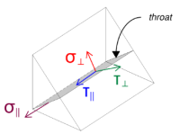
Beachten, ohne andere Kräfte anwesend. Dies bedeutet, dass die senkrechten Belastungen als Null angenommen werden können, und nur das Scherspannung in paralleler Richtung muss berechnet werden.
\(
\sigma_{\Täter} = frac{N.}{(L_{w,Spitze&Unterseite})\,a sqrt{2}}
= frac{0 \,\Text{kN}}{(312 \,\Text{mm}) \mal 5.657 \,\Text{mm} \mal sqrt{2}}
= 0
\)
\(
\Ihre_{\Täter} = frac{0}{(L_{w,Spitze&Unterseite})\,a sqrt{2}}
= frac{0 \,\Text{kN}}{(312 \,\Text{mm}) \mal 5.657 \,\Text{mm} \mal sqrt{2}}
= 0
\)
\(
\Ihre_{\parallel} = frac{V_{mit}}{(L_{w,Spitze&Unterseite})\,ein}
= frac{5 \,\Text{kN}}{(312 \,\Text{mm}) \mal 5.657 \,\Text{mm}}
= 2.8329 \,\Text{MPa}
\)
Verwenden von IM 1993-1-8:2005, Gl. 4.1, Die Entwurfsschweißspannung wird unter Verwendung der Richtungsmethode erhalten.
\(
F_{w,Ed1} = Quadrat{ (\sigma_{\Täter})^ 2 + 3 \links( (\Ihre_{\Täter})^ 2 + (\Ihre_{\parallel})^2 rechts) }
= Quadrat{ (0)^ 2 + 3 \mal links( (0)^ 2 + (2.8329 \,\Text{MPa})^2 rechts) }
= 4.9067 \,\Text{MPa}
\)
Zusätzlich, Das Design normaler Spannung für die Basismetallprüfung, pro IM 1993-1-8:2005, Gl. 4.1, wird als Null angenommen, schon seit Kein normaler Stress ist vorhanden.
\(
F_{w,Ed2} = sigma_{\Täter} = 0
\)
Jetzt, Lassen Sie uns die bewerten linke und rechte Schweißnähte. Wie bei den oberen und unteren Schweißnähten, Wir berechnen zuerst die Gesamtschweißlänge.
\(
L_{w,links&richtig} = 2 \links(d_{col} – 2t_{col} – 2r_{col}\richtig)
= 2 \mal links(180 \,\Text{mm} – 2 \mal 8 \,\Text{mm} – 2 \mal 4 \,\Text{mm}\richtig)
= 312 \,\Text{mm}
\)
Wir berechnen dann die Komponenten der Schweißbelastungen.
\(
\sigma_{\Täter} = frac{N.}{(L_{w,links&richtig})\,a sqrt{2}}
= frac{0 \,\Text{kN}}{(312 \,\Text{mm}) \mal 5.657 \,\Text{mm} \mal sqrt{2}}
= 0
\)
\(
\Ihre_{\Täter} = frac{0}{(L_{w,links&richtig})\,a sqrt{2}}
= frac{0 \,\Text{kN}}{(312 \,\Text{mm}) \mal 5.657 \,\Text{mm} \mal sqrt{2}}
= 0
\)
\(
\Ihre_{\parallel} = frac{V_y}{(L_{w,links&richtig})\,ein}
= frac{5 \,\Text{kN}}{(312 \,\Text{mm}) \mal 5.657 \,\Text{mm}}
= 2.8329 \,\Text{MPa}
\)
Verwenden von IM 1993-1-8:2005, Gl. 4.1, Wir bestimmen sowohl die Schweißspannung des Designs als auch die Normalspannung des Designs für die Basismetallprüfung.
\(
F_{w,Ed1} = Quadrat{ \links( \sigma_{\Täter} \richtig)^ 2 + 3 \links( \links( \Ihre_{\Täter} \richtig)^ 2 + \links( \Ihre_{\parallel} \richtig)^2 rechts) }
\)
\(
F_{w,Ed1} = Quadrat{ \links( 0 \richtig)^ 2 + 3 \mal links( \links( 0 \richtig)^ 2 + \links( 2.8329 \,\Text{MPa} \richtig)^2 rechts) }
\)
\(
F_{w,Ed1} = 4.9067 \,\Text{MPa}
\)
Der nächste Schritt besteht darin, die zu identifizieren Regierungsschweißstress zwischen den oberen/unteren Schweißnähten und den linken/rechten Schweißnähten. Da die Schweißlängen gleich sind und die angelegten Lasten die gleiche Größe haben, Die resultierenden Schweißspannungen sind gleich.
\(
F_{w,Ed1} = max(F_{w,Ed1}, \, F_{w,Ed1})
= max(4.9067 \,\Text{MPa}, \, 4.9067 \,\Text{MPa})
= 4.9067 \,\Text{MPa}
\)
Die Grundmetallspannung bleibt Null.
\(
F_{w,Ed2} = max(F_{w,Ed2}, \, F_{w,Ed2}) = max(0, \, 0) = 0
\)
Jetzt, Wir berechnen die Schweißkapazität. Zuerst, der Widerstand des Filetschweißung wird berechnet. Dann, der Widerstand des Grundmetall wird bestimmt. Mit EN 1993-1-8:2005, Gl. 4.1, Die Kapazitäten werden wie folgt berechnet:
\(
F_{w,Rd1} = frac{F_U}{\Beta_W links(\Um es zu berechnen{M2, bald}\richtig)}
= frac{360 \,\Text{MPa}}{0.8 \mal (1.25)}
= 360 \,\Text{MPa}
\)
\(
F_{w,RD2} = frac{0.9 F_U}{\Um es zu berechnen{M2, bald}}
= frac{0.9 \mal 360 \,\Text{MPa}}{1.25}
= 259.2 \,\Text{MPa}
\)
Schließlich, Wir vergleichen die Schweißbelastungen mit den Schweißkapazitäten, und die Grundmetallspannungen mit den Grundmetallkapazitäten.
Schon seit 4.9067 MPa < 360 MPa und 0 MPa < 259.2 MPa, Die Kapazität der geschweißten Verbindung ist ausreichend.
Prüfen #2: Berechnen Sie die Betonausbruchkapazität aufgrund von VY -Scherung
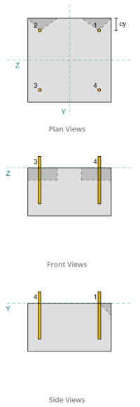
Nach den Bestimmungen von IM 1992-4:2018, Die Kante senkrecht zur angelegten Last wird auf Scherausbruchversagen bewertet. Nur die Verankerungen, die dieser Kante am nächsten liegen werden als verlobt angesehen, Während die verbleibenden Anker nicht der Schere widerstehen sollen.
Diese Kantenanker müssen einen Betonkantenabstand haben, der größer ist als der größere von 10 · HEF und 60 · D., wo haben ist die Einbettungslänge und d ist der Ankerdurchmesser. Wenn dieser Zustand nicht erfüllt ist, Die Dicke der Grundplatte muss weniger als 0,25 · HEF betragen.
Wenn die Anforderungen in IM 1992-4:2018, Klausel 7.2.2.5(1), sind nicht zufrieden, Die SkyCiv -Software kann die Designprüfungen nicht durchführen, und dem Benutzer wird empfohlen, sich auf andere relevante Standards zu verweisen.
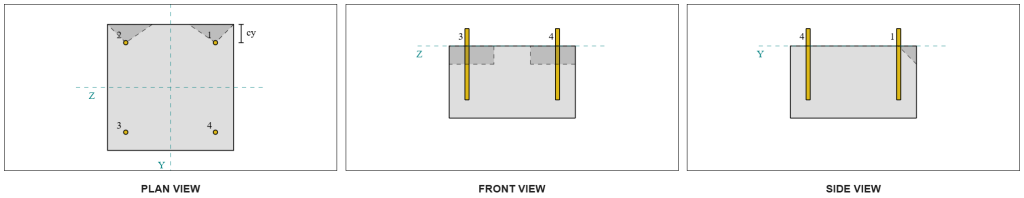
Aus den Skyciv -Software Ergebnissen, Die Kantenanker wirken als einzelne Anker, Da überlappen sich ihre projizierten Bereiche nicht. Für diese Berechnung, Anker 1 wird berücksichtigt.
Berechnung des Teils der Vy -Scherlast, die vom Anker getragen wird 1, Die gesamte Vy -Scherung wird auf die dem Rand am nächsten gelegenen Anker verteilt. Dies gibt dem senkrechte Kraft am Anker 1.
\(
V_{\Täter} = frac{V_y}{N_{ein,s}}
= frac{5 \,\Text{kN}}{2}
= 2.5 \,\Text{kN}
\)
Für die parallele Kraft, Es wird angenommen, dass alle Anker der Belastung gleichermaßen widerstehen. Deshalb, Die parallele Komponente der Last wird berechnet als:
\(
V_{\parallel} = frac{V_z}{N_{anc}}
= frac{5 \,\Text{kN}}{4}
= 1.25 \,\Text{kN}
\)
Mit der Gesamtscherlast am Anker 1 ist also:
\(
V_{Ed} = Quadrat{ \links( V_{\Täter} \richtig)^ 2 + \links( V_{\parallel} \richtig)^ 2 }
\)
\(
V_{Ed} = Quadrat{ \links( 2.5 \,\Text{kN} \richtig)^ 2 + \links( 1.25 \,\Text{kN} \richtig)^ 2 } = 2.7951 \,\Text{kN}
\)
Der erste Teil der Kapazitätsberechnung besteht darin, die zu bestimmen Alpha- und Beta -Faktoren. Wir verwenden IM 1992-4:2018, Klausel 7.2.2.5, um das zu setzen LF -Dimension, und Gleichungen 7.42 und 7.43 um die Faktoren zu bestimmen.
\(
l_f = min(h_{ef}, \, 12d_{anc})
= min(150 \,\Text{mm}, \, 12 \mal 12 \,\Text{mm})
= 144 \,\Text{mm}
\)
\(
\Alpha = 0.1 \links(\frac{l_f}{c_{1,s1}}\richtig)^{0.5}
= 0.1 \mal links(\frac{144 \,\Text{mm}}{50 \,\Text{mm}}\richtig)^{0.5}
= 0.16971
\)
\(
\Beta = 0.1 \links(\frac{d_{anc}}{c_{1,s1}}\richtig)^{0.2}
= 0.1 \mal links(\frac{12 \,\Text{mm}}{50 \,\Text{mm}}\richtig)^{0.2}
= 0.07517
\)
Der nächste Schritt besteht darin, die zu berechnen Anfangswert des charakteristischen Widerstands des Befestigungsmittels. Verwenden von IM 1992-4:2018, Gleichung 7.41, Der Wert ist:
\(
V^{0}_{Rk,c} = k_9 links( \frac{d_{anc}}{\Text{mm}} \richtig)^{\Alpha}
\links( \frac{l_f}{\Text{mm}} \richtig)^{\Beta}
\sqrt{ \frac{f_{ck}}{\Text{MPa}} }
\links( \frac{c_{1,s1}}{\Text{mm}} \richtig)^{1.5} N.
\)
\(
V^{0}_{Rk,c} = 1.7 \mal links( \frac{12 \,\Text{mm}}{1 \,\Text{mm}} \richtig)^{0.16971}
\mal links( \frac{144 \,\Text{mm}}{1 \,\Text{mm}} \richtig)^{0.07517}
\mal sqrt{ \frac{20 \,\Text{MPa}}{1 \,\Text{MPa}} }
\mal links( \frac{50 \,\Text{mm}}{1 \,\Text{mm}} \richtig)^{1.5}
\mal 0.001 \,\Text{kN}
\)
\(
V^{0}_{Rk,c} = 5.954 \,\Text{kN}
\)
Dann, Wir berechnen die Referenz projizierter Bereich eines einzelnen Ankers, folgende IM 1992-4:2018, Gleichung 7.44.
\(
EIN_{c,V }^{0} = 4.5 \links( c_{1,s1} \richtig)^ 2
= 4.5 \mal links( 50 \,\Text{mm} \richtig)^ 2
= 11250 \,\Text{mm}^ 2
\)
Danach, Wir berechnen die Tatsächlicher projizierter Bereich Anker 1.
\(
B_{c,V } = min(c_{links,s1}, \, 1.5c_{1,s1}) + \Min.(c_{richtig,s1}, \, 1.5c_{1,s1})
\)
\(
B_{c,V } = min(300 \,\Text{mm}, \, 1.5 \mal 50 \,\Text{mm}) + \Min.(50 \,\Text{mm}, \, 1.5 \mal 50 \,\Text{mm}) = 125 \,\Text{mm}
\)
\(
Um es zu berechnen{c,V } = min(1.5c_{1,s1}, \, t_{konz}) = min(1.5 \mal 50 \,\Text{mm}, \, 200 \,\Text{mm}) = 75 \,\Text{mm}
\)
\(
EIN_{c,V } Die Hälfte der Wandhöhe von der Unterseite der Basis für den Fall des{c,V } B_{c,V } = 75 \,\Text{mm} \mal 125 \,\Text{mm} = 9375 \,\Text{mm}^ 2
\)
Wir müssen auch die Parameter für die Scherausbruch berechnen. Wir verwenden IM 1992-4:2018, Gleichung 7.4, Um den Faktor zu erhalten, der das erklärt Störung der Stressverteilung, Gleichung 7.46 Für den Faktor, der die berücksichtigt Mitgliedsdicke, und Gleichung 7.48 Für den Faktor, der die berücksichtigt Einfluss einer Scherlast, die zum Rand geneigt ist. Diese werden wie folgt berechnet:
\(
\Psi_{s,V } = min links( 0.7 + 0.3 \links( \frac{c_{2,s1}}{1.5c_{1,s1}} \richtig), \, 1.0 \richtig)
= min links( 0.7 + 0.3 \mal links( \frac{50 \,\Text{mm}}{1.5 \mal 50 \,\Text{mm}} \richtig), \, 1 \richtig)
= 0.9
\)
\(
\Psi_{h,V } = max links( \links( \frac{1.5c_{1,s1}}{t_{konz}} \richtig)^{0.5}, \, 1 \richtig)
= max links( \links( \frac{1.5 \mal 50 \,\Text{mm}}{200 \,\Text{mm}} \richtig)^{0.5}, \, 1 \richtig)
= 1
\)
\(
\= Abstand des Abschnitts, in dem die Scherung berücksichtigt wird, zur Fläche des nächsten Auflagers{V } = tan^{-1} \links( \frac{V_{\parallel}}{V_{\Täter}} \richtig)
= tan^{-1} \links( \frac{1.25 \,\Text{kN}}{2.5 \,\Text{kN}} \richtig)
= 0.46365 \,\Text{Arbeit}
\)
\(
\Psi_{\Alpha,V } = max links(
\sqrt{ \frac{1}{(\cos(\= Abstand des Abschnitts, in dem die Scherung berücksichtigt wird, zur Fläche des nächsten Auflagers{V }))^ 2 + \links( 0.5 \, (\ohne(\= Abstand des Abschnitts, in dem die Scherung berücksichtigt wird, zur Fläche des nächsten Auflagers{V })) \richtig)^ 2 } }, \, 1 \richtig)
\)
\(
\Psi_{\Alpha,V } = max links(
\sqrt{ \frac{1}{(\cos(0.46365 \,\Text{Arbeit}))^ 2 + \links( 0.5 \Zeiten sin(0.46365 \,\Text{Arbeit}) \richtig)^ 2 } }, \, 1 \richtig)
\)
\(
\Psi_{\Alpha,V } = 1.0847
\)
Eine wichtige Anmerkung bei der Bestimmung des Alpha -Faktor.
Schließlich, Wir berechnen die Breakout -Widerstand des einzelnen Ankers verwenden IM 1992-4:2018, Gleichung 7.1.
\(
V_{Rk,c} = V^0_{Rk,c} \links(\frac{EIN_{c,V }}{A^0_{c,V }}\richtig)
\Psi_{s,V } \Psi_{h,V } \Psi_{ec,V } \Psi_{\Alpha,V } \Psi_{Ausbruchkegelbereich für Einzeldübel nicht durch Kanten beeinflusst,V }
\)
\(
V_{Rk,c} = 5.954 \,\Text{kN} \mal links(\frac{9375 \,\Text{mm}^ 2}{11250 \,\Text{mm}^ 2}\richtig)
\mal 0.9 \mal 1 \mal 1 \mal 1.0847 \mal 1
= 4.8435 \,\Text{kN}
\)
Anwenden des Teilfaktors, Der Konstruktionswiderstand ist 3.23 kN.
\(
V_{Rd,c} = frac{V_{Rk,c}}{\Um es zu berechnen{Mc}}
= frac{4.8435 \,\Text{kN}}{1.5}
= 3.229 \,\Text{kN}
\)
Schon seit 2.7951 kN < 3.229 kN, Die Scherausbruchkapazität für Vy -Scher ist ausreichend.
Prüfen #3: Berechnen Sie die Betonausbruchkapazität aufgrund von VZ -Scherung
Der gleiche Ansatz wird verwendet, um die Kapazität am Rand senkrecht zur VZ -Scherung zu bestimmen.
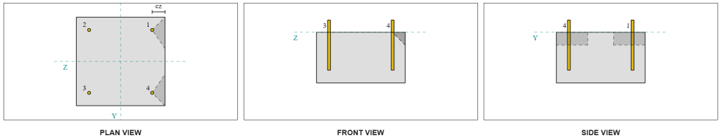
Wegen des symmetrischen Designs, Die Anker, die sich gegen Vz -Scherung widersetzen, werden ebenfalls als identifiziert als einzelne Anker. Lassen Sie uns nachdenken Anker 1 Wieder für die Berechnungen.
Zur Berechnung der senkrechte Belastung am Anker 1, Wir teilen die VZ -Schere durch die Gesamtzahl der Ankern, die nur der Kante am nächsten liegen. Zur Berechnung der parallele Last am Anker 1, Wir teilen die Vy -Scherung durch die Gesamtzahl der Anker.
\(
V_{\Täter} = frac{V_{mit}}{N_{ein,s}}
= frac{5 \,\Text{kN}}{2}
= 2.5 \,\Text{kN}
\)
\(
V_{\parallel} = frac{V_{j}}{N_{anc}}
= frac{5 \,\Text{kN}}{4}
= 1.25 \,\Text{kN}
\)
\(
V_{Ed} = Quadrat{ \links( V_{\Täter} \richtig)^ 2 + \links( V_{\parallel} \richtig)^ 2 }
\)
\(
V_{Ed} = Quadrat{ \links( 2.5 \,\Text{kN} \richtig)^ 2 + \links( 1.25 \,\Text{kN} \richtig)^ 2 }
= 2.7951 \,\Text{kN}
\)
Verwenden eines ähnlichen Ansatzes zur Überprüfung #2, das resultierende Breakout -Widerstand Denn die Kante senkrecht zur VZ -Scherung ist:
\(
V_{Rd,c} = frac{V_{Rk,c}}{\Um es zu berechnen{Mc}}
= frac{4.8435 \,\Text{kN}}{1.5}
= 3.229 \,\Text{kN}
\)
Schon seit 2.7951 kN < 3.229 kN, Die Scherausbruchkapazität für VZ -Scher ist ausreichend.
Prüfen #4: Berechnen Sie die Kapazität der Beton -Pryout
Die Berechnung für die Scher -Pryout -Widerstand beinhaltet die Bestimmung der Nennkapazität der Anker gegen Spannungsausbrüche. Die Referenz für die Spannungsausbruchkapazität ist IM 1992-4:2018, Klausel 7.2.1.4. Eine detaillierte Diskussion des Spannungsausbruchs ist bereits in der behandelt Beispiel für Skyciv -Design mit Spannungslast und wird in diesem Designbeispiel nicht wiederholt.
Aus den Skyciv -Softwareberechnungen, Die nominelle Kapazität des Abschnitts für Spannungsausbruch ist 44.61 kN.
Wir verwenden dann IM 1992-4:2018, Gleichung 7.39a, Um den Entwurfs charakteristischen Widerstand zu erhalten. Verwenden von K8 = 2, Die Kapazität ist 59.48 kN.
\(
V_{Rd,cp} = frac{K_8 n_{cbg}}{\Gamma_c}
= frac{2 \mal 44.608 \,\Text{kN}}{1.5}
= 59.478 \,\Text{kN}
\)
Im Scher -Pryout -Scheck, Alle Anker sind effektiv Im Widerspruch der vollen Scherbelastung. Aus dem von der Skyciv -Software erzeugten Bild, Alle Versagenskegelprojektionen überschneiden sich miteinander, die Anker als eine wirken Ankergruppe.
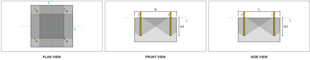
Deshalb, Der erforderliche Widerstand der Ankergruppe ist die insgesamt resultierende Scherlast von 7.07 kN.
\(
V_{res} = Quadrat{(V_y)^ 2 + (V_z)^ 2}
= Quadrat{(5 \,\Text{kN})^ 2 + (5 \,\Text{kN})^ 2}
= 7.0711 \,\Text{kN}
\)
\(
V_{Ed} = left(\frac{V_{res}}{N_{anc}}\richtig) N_{ein,G1}
= left(\frac{7.0711 \,\Text{kN}}{4}\richtig) \mal 4
= 7.0711 \,\Text{kN}
\)
Schon seit 7.0711 kN < 59.478 kN, Die Scher -Pryout -Kapazität ist ausreichend.
Prüfen #5: Berechnen Sie die Scherkapazität der Ankerstange
Die Berechnung der Ankerstangenscherungkapazität hängt davon ab, ob die Scherlast mit einem Momentarm aufgetragen wird. Um dies zu bestimmen, Wir beziehen uns auf IM 1992-4:2018, Klausel 6.2.2.3, Wo die Dicke und das Material des Fugenmörtels, die Anzahl der Befestigungselemente im Design, Der Abstand der Befestigungselemente, und andere Faktoren werden überprüft.
Mit der Skyciv Base Plate Design Software führt alle erforderlichen Schecks durch, um festzustellen, ob die Scherlast wirkt mit oder ohne Hebelarm. Für dieses Designbeispiel, Es wird festgestellt, dass die Scherlast ist nicht mit einem Hebelarm aufgetragen. Deshalb, Wir verwenden IM 1992-4:2018, Klausel 7.2.2.3.1, Für die Kapazitätsgleichungen.
Wir beginnen mit der Berechnung des charakteristischen Widerstands des Stahlverbots mit IM 1992-4:2018, Gleichung 7.34.
\(
V^0_{Rk,s} = k_6 a_s f_{u,anc}
= 0.5 \mal 113.1 \,\Text{mm}^2 mal 800 \,\Text{MPa}
= 45.239 \,\Text{kN}
\)
Als nächstes, Wir wenden den Faktor für die an Duktilität des einzelnen Ankers oder der Ankergruppe, Einnahme K7 = 1.
\(
V_{Rk,s} = k_7 v^{0}_{Rk,s}
= 1 \mal 45.239 \,\Text{kN}
= 45.239 \,\Text{kN}
\)
Wir erhalten dann die Teilfaktor für Stahlscherversagen mit IM 1992-4:2018, Tabelle 4.1. Für einen Anker mit 8.8 des Materials , Der resultierende Teilfaktor ist:
\(
\Um es zu berechnen{MS,Schub-}
= max links( 1.0 \links( \frac{F_{u,anc}}{F_{j,anc}} \richtig), \, 1.25 \richtig)
= max links( 1 \mal frac{800 \,\Text{MPa}}{640 \,\Text{MPa}}, \, 1.25 \richtig)
= 1.25
\)
Anwenden dieses Faktors auf den charakteristischen Widerstand anwenden, Der Konstruktionswiderstand ist 36.19 kN.
\(
V_{Rd,s} = frac{V_{Rk,s}}{\Um es zu berechnen{MS,Schub-}}
= frac{45.239 \,\Text{kN}}{1.25}
= 36.191 \,\Text{kN}
\)
Mit der Erforderlicher Scherbeständigkeit pro Ankerstange ist die resultierende Scherlast geteilt durch die Gesamtzahl der Ankerstangen, die berechnet zu 1.77 kN.
\(
V_{Ed} = frac{\sqrt{ (V_y)^ 2 + (V_z)^ 2 }}{N_{anc}}
\)
\(
V_{Ed} = frac{\sqrt{ (5 \,\Text{kN})^ 2 + (5 \,\Text{kN})^ 2 }}{4}
= 1.7678 \,\Text{kN}
\)
Schon seit 1.7678 kN < 36.191 kN, Die Scherkapazität der Ankerstabstahl ist ausreichend.
Prüfen #6: Berechnen Sie die Tragfähigkeit der Grundplatte
Ein zusätzliches Prüfung des Lagerwiderstands der Grundplatte wurde in einem späteren Update der Software eingeführt. Bitte siehe diesen Link für eine Beispielrechnung und ausführliche Erläuterung.
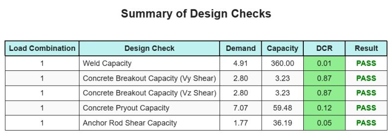
Entwurfszusammenfassung
Mit der Skyciv Base Plate Design Software kann automatisch einen Schritt-für-Schritt-Berechnungsbericht für dieses Entwurfsbeispiel erstellen. Es enthält auch eine Zusammenfassung der durchgeführten Schecks und deren resultierenden Verhältnisse, Die Informationen auf einen Blick leicht zu verstehen machen. Im Folgenden finden Sie eine Stichprobenzusammenfassungstabelle, Welches ist im Bericht enthalten.
SKYCIV -Beispielbericht
Sehen Sie sich den Detaillierungsgrad und die Klarheit an, die Sie von einem SkyCiv-Grundplatten-Designbericht erwarten können. Der Bericht umfasst alle wichtigen Designprüfungen, Gleichungen, und Ergebnisse werden in einem klaren und leicht lesbaren Format präsentiert. Es entspricht vollständig den Designstandards. Klicken Sie unten, um einen Beispielbericht anzuzeigen, der mit dem SkyCiv-Grundplattenrechner erstellt wurde.
Basisplattensoftware kaufen
Kaufen Sie die Vollversion des Basisplatten -Designmoduls selbst ohne andere Skyciv -Module selbst. Auf diese Weise erhalten Sie einen vollständigen Satz von Ergebnissen für die Basisplattendesign, Einbeziehung detaillierter Berichte und mehr Funktionen.