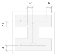
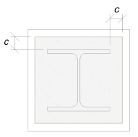
Basisplatten -Design -Beispiel mit eN 1993-1-8-2005, IM 1993-1-1-2005 und EN 1992-1-1-2004
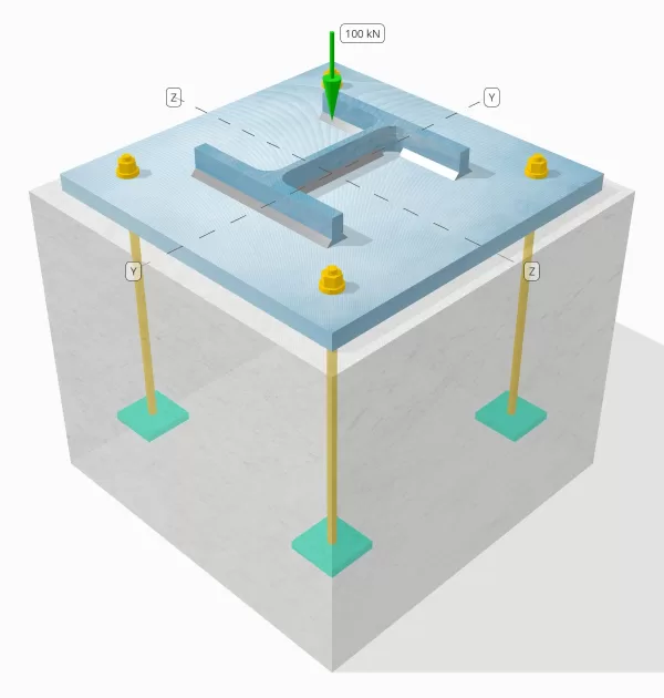
Problemanweisung:
Determine whether the designed column-to-base plate connection is sufficient for a 1500-kN compression load, 12-kN Vz shear load, and 25-kN Vy shear load.
Gegebene Daten:
Spalte:
Spaltenabschnitt: HP 360×180
Säulenbereich: 23000 mm2
Säulenmaterial: S275N
Grundplatte:
Grundplattenabmessungen: 750 mmx 750 mm
Grundplattendicke: 25 mm
Grundplattenmaterial: S235
Fugenmörtel:
Fugenmörtel Dicke: 0 mm
Beton:
Konkrete Abmessungen: 750 mmx 750 mm
Betondicke: 380 mm
Betonmaterial: C20/25
Anker:
Ankerdurchmesser: 24 mm
Effektive Einbettungslänge: 300 mm
Anchor Ending: Rectangular Plate
Embedded plate Width: 100 mm
Dicke eingebetteter Platten: 16 mm
Schweißnähte:
Schweißnahtgröße: 12 mm
Füllmetallklassifizierung: E38
Drucklast nur durch Schweißnähte übertragen? Ja
Ankerdaten (von Skyciv -Taschenrechner):
Anmerkungen:
The purpose of this design example is to demonstrate the step-by-step calculations for capacity checks involving concurrent shear and axial loads. Some of the required checks have already been discussed in the previous design examples. Please refer to the links provided in each section.
Schritt-für-Schritt-Berechnungen:
Prüfen #1: Berechnen Sie die Schweißkapazität
In determining the weld demand, the SkyCiv calculator assumes that the Vy shear load is resisted by the web alone, bleibt die Vz shear load is resisted by the flanges alone, und das compression load is resisted by the entire section.
Zuerst, wir berechnen die Gesamtschweißlänge on the section.
\(L_{\Text{schweißen}} = 2 B_F + 2(d_{\Text{col}} – 2 t_f – 2 r_{\Text{col}}) + 2(B_F – t_w – 2 r_{\Text{col}})\)
\(L_{\Text{schweißen}} = 2 \mal 378.8\ \Text{mm} + 2 \mal (362.9\ \Text{mm} – 2 \mal 21.1\ \Text{mm} – 2 \mal 15.2\ \Text{mm}) + 2 \mal (378.8\ \Text{mm} – 21.1\ \Text{mm} – 2 \mal 15.2\ \Text{mm})\)
\(L_{\Text{schweißen}} = 1992.8\ \Text{mm}\)
Dann, wir berechnen die weld lengths at the Flansche und das Netz.
\(L_{w,flg} = 2 B_F + 2(B_F – t_w – 2 r_{col}) = 2 \mal 378.8\ \Text{mm} + 2 \mal (378.8\ \Text{mm} – 21.1\ \Text{mm} – 2 \mal 15.2\ \Text{mm}) = 1412.2\ \Text{mm}\)
\(L_{w,Netz} = 2\,(d_{col} – 2t_f – 2r_{col}) = 2 \mal (362.9\ \Text{mm} – 2 \mal 21.1\ \Text{mm} – 2 \mal 15.2\ \Text{mm}) = 580.6\ \Text{mm}\)
Considering the flanges first, bleibt die normal und shear stresses werden mit berechnet IM 1993-1-8:2005 Klausel 4.5.3.2.
\(\sigma_{\Täter} = frac{N_x}{L_{\Text{schweißen}} a_{flg} \sqrt{2}} = frac{1500\ \Text{kN}}{1992.8\ \Text{mm} \mal 8.485\ \Text{mm} \mal sqrt{2}} = 62.728\ \Text{MPa}\)
\(\Ihre_{\Täter} = frac{N_x}{L_{\Text{schweißen}} a_{flg} \sqrt{2}} = frac{1500\ \Text{kN}}{1992.8\ \Text{mm} \mal 8.485\ \Text{mm} \mal sqrt{2}} = 62.728\ \Text{MPa}\)
\(\eta_{\parallel} = frac{V_z}{L_{w,flg} a_{flg}} = frac{12\ \Text{kN}}{1412.2\ \Text{mm} \mal 8.485\ \Text{mm}} = 1.0015\ \Text{MPa}\)
Verwenden von IM 1993-1-8:2005 Gl. (4.1), bleibt die design weld stress based on the directional method is then obtained.
\(F_{w,Ed1} = Quadrat{(\sigma_{\Täter})^ 2 + 3\links((\Ihre_{\Täter})^ 2 + (\eta_{\parallel})^2\right)}\)
\(F_{w,Ed1} = Quadrat{(62.728\ \Text{MPa})^ 2 + 3 \mal links((62.728\ \Text{MPa})^ 2 + (1.0015\ \Text{MPa})^2\right)}\)
\(F_{w,Ed1} = 125.47\ \Text{MPa}\)
Dann, bleibt die design perpendicular stress auf der Grundmetall wird bestimmt.
\(F_{w,Ed2} = sigma_{\Täter} = 62.728\ \Text{MPa}\)
For the web, we use the same formula to calculate the normal und shear stresses, which gives the corresponding design weld stress und design base metal stress.
\(\sigma_{\Täter} = frac{N_x}{L_{\Text{schweißen}} a_{\Text{Netz}} \sqrt{2}} = frac{1500\ \Text{kN}}{1992.8\ \Text{mm} \mal 8.485\ \Text{mm} \mal sqrt{2}} = 62.728\ \Text{MPa}\)
\(\Ihre_{\Täter} = frac{N_x}{L_{\Text{schweißen}} a_{\Text{Netz}} \sqrt{2}} = frac{1500\ \Text{kN}}{1992.8\ \Text{mm} \mal 8.485\ \Text{mm} \mal sqrt{2}} = 62.728\ \Text{MPa}\)
\(\Ihre_{\parallel} = frac{V_y}{L_{w,\Text{Netz}} a_{\Text{Netz}}} = frac{25\ \Text{kN}}{580.6\ \Text{mm} \mal 8.485\ \Text{mm}} = 5.0747\ \Text{MPa}\)
\(F_{w,Ed1} = Quadrat{(\sigma_{\Täter})^ 2 + 3\links((\Ihre_{\Täter})^ 2 + (\Ihre_{\parallel})^2\right)}\)
\(F_{w,Ed1} = Quadrat{(62.728\ \Text{MPa})^ 2 + 3 \mal links((62.728\ \Text{MPa})^ 2 + (5.0747\ \Text{MPa})^2\right)}\)
\(F_{w,Ed1} = 125.76\ \Text{MPa}\)
\(F_{w,Ed2} = sigma_{\Täter} = 62.728\ \Text{MPa}\)
We then take the governing stress between the Flansch und web weld groups.
\(F_{w,Ed1} = max(F_{w,Ed1},\ F_{w,Ed1}) = max(125.47\ \Text{MPa},\ 125.76\ \Text{MPa}) = 125.76\ \Text{MPa}\)
\(F_{w,Ed2} = max(F_{w,Ed2},\ F_{w,Ed2}) = max(62.728\ \Text{MPa},\ 62.728\ \Text{MPa}) = 62.728\ \Text{MPa}\)
Als nächstes, we calculate the weld capacity using IM 1993-1-8:2005 Gl. (4.1). Mit der ultimate tensile strength (das Programm weist Länge zu) used in this equation is the minimum value among the column, base plate, and weld metal.
\(f_u = \min(f_{u,\Text{col}},\ f_{u,\Text{bp}},\ f_{Ihre}) = min(370\ \Text{MPa},\ 360\ \Text{MPa},\ 470\ \Text{MPa}) = 360\ \Text{MPa}\)
\(F_{w,Rd1} = frac{F_U}{\beta_w\,(\Um es zu berechnen{M2,\text{schweißen}})} = frac{360\ \Text{MPa}}{0.8 \mal (1.25)} = 360\ \Text{MPa}\)
Mit der Widerstand des Grundmetalls is also calculated using the same equation.
\(F_{w,RD2} = frac{0.9 F_U}{\Um es zu berechnen{M2,\text{schweißen}}} = frac{0.9 \mal 360\ \Text{MPa}}{1.25} = 259.2\ \Text{MPa}\)
Schließlich, we compare the fillet weld resistance zum design weld stress, und das base metal resistance zum base metal stress.
Schon seit 125.76 MPa < 360 MPa, the weld capacity is sufficient.
Prüfen #2: Calculate concrete bearing capacity and base plate yield capacity
A design example for the concrete bearing capacity and base plate yield capacity is already discussed in the Base Plate Design Example for Compression. Please refer to this link for the step-by-step calculation.
Prüfen #3: Calculate base plate bearing capacity (Vy shear)
When shear is transferred through the anchor rods, the rods bear against the base plate. Deshalb, we need to verify that the base plate has sufficient capacity to resist the Lagerbelastung at the anchor holes.
Mit der design shear force per anchor rod is calculated as the total shear load divided by the total number of anchors.
\(F_{b,Ed} = frac{V_y}{N_{anc}} = frac{25\ \Text{kN}}{10} = 2.5\ \Text{kN}\)
Als nächstes, we determine the factors required for the bearing resistance Berechnung. Gemäß IM 1993-1-8:2005 Tabelle 3.4, we obtain the \(\alpha_d\), \(\alpha_b\), und \(k_1\) Faktoren.
Beide Ende und inner anchors are considered when determining the corresponding \(\alpha_d\) Faktoren.
\(\= Abstand des Abschnitts, in dem die Scherung berücksichtigt wird, zur Fläche des nächsten Auflagers{d,\Text{Ende}} = frac{l_{\Text{Kante},j}}{3 d_{\Text{hole}}} = frac{100\ \Text{mm}}{3 \mal 26\ \Text{mm}} = 1.2821\)
\(\= Abstand des Abschnitts, in dem die Scherung berücksichtigt wird, zur Fläche des nächsten Auflagers{d,\Text{innere}} = frac{S_}{3 d_{\Text{hole}}} – \frac{1}{4} = frac{550\ \Text{mm}}{3 \mal 26\ \Text{mm}} – \frac{1}{4} = 6.8013\)
Using the smaller \(\alpha_d\) Faktor, die entsprechende \(\alpha_b\) Faktor is calculated as:
\(\alpha_b = \min\left(\= Abstand des Abschnitts, in dem die Scherung berücksichtigt wird, zur Fläche des nächsten Auflagers{d,\Text{Ende}},\ \= Abstand des Abschnitts, in dem die Scherung berücksichtigt wird, zur Fläche des nächsten Auflagers{d,\Text{innere}},\ \frac{F_{u,\Text{anc}}}{f_{u,\Text{bp}}},\ 1.0\richtig) = \min\left(1.2821,\ 6.8013,\ \frac{800\ \Text{MPa}}{360\ \Text{MPa}},\ 1\richtig) = 1\)
Ähnlich, both Kante und inner bolts are considered when determining the \(k_1\) Faktoren.
\(k_{1,\Text{Kante}} = \min\left(2.8\links(\frac{l_{\Text{Kante},mit}}{d_{\Text{hole}}}\richtig) – 1.7,\ 1.4\links(\frac{s_z}{d_{\Text{hole}}}\richtig) – 1.7,\ 2.5\richtig)\)
\(k_{1,\Text{Kante}} = \min\left(2.8 \mal frac{75\ \Text{mm}}{26\ \Text{mm}} – 1.7,\ 1.4 \mal frac{150\ \Text{mm}}{26\ \Text{mm}} – 1.7,\ 2.5\richtig) = 2.5\)
\(k_{1,\Text{innere}} = \min\left(1.4\links(\frac{s_z}{d_{\Text{hole}}}\richtig) – 1.7,\ 2.5\richtig) = \min\left(1.4 \mal frac{150\ \Text{mm}}{26\ \Text{mm}} – 1.7,\ 2.5\richtig) = 2.5\)
Das Regierende \(k_1\) Faktor, corresponding to the smaller value, ist:
\(k_1 = \min(k_{1,\Text{Kante}},\ k_{1,\Text{innere}}) = min(2.5,\ 2.5) = 2.5\)
Schließlich, wir berechnen die bearing resistance using the equation from IM 1993-1-8:2005 Tabelle 3.4.
\(F_{b,Rd} = frac{k_1 \alpha_b f_{u\_bp} d_{anc} t_{bp}}{\Um es zu berechnen{M2,anchor}} \frac{2.5 \mal 1 \mal 360 \Text{ MPa} \mal 24 \Text{ mm} \mal 25 \Text{ mm}}{1.25} = 432 \Text{ kN} \)
Schon seit 2.5 kN < 432 kN, the base plate bearing capacity is sufficient.
Prüfen #4: Calculate base plate bearing capacity (Vz shear)
Die Berechnung für die bearing capacity under Vz shear follows the same procedure as that for Vy shear, but considering the geometry along the Vz shear axis.
Mit der anchor demand wegen Vz shear ist:
\(F_{b,Ed} = frac{V_z}{N_{anc}} = frac{12\ \Text{kN}}{10} = 1.2\ \Text{kN}\)
Verwenden von IM 1993-1-8:2005 Tabelle 3.4, the factors are determined as follows:
\( \= Abstand des Abschnitts, in dem die Scherung berücksichtigt wird, zur Fläche des nächsten Auflagers{d,\Text{Ende}} = frac{l_{\Text{Kante},mit}}{3 d_{\Text{hole}}} = frac{75\ \Text{mm}}{3 \mal 26\ \Text{mm}} = 0.96154 \)
\( \= Abstand des Abschnitts, in dem die Scherung berücksichtigt wird, zur Fläche des nächsten Auflagers{d,\Text{innere}} = frac{s_z}{3 d_{\Text{hole}}} – \frac{1}{4} = frac{150\ \Text{mm}}{3 \mal 26\ \Text{mm}} – \frac{1}{4} = 1.6731 \)
\( \alpha_b = \min\!\links(\= Abstand des Abschnitts, in dem die Scherung berücksichtigt wird, zur Fläche des nächsten Auflagers{d,\Text{Ende}},\ \= Abstand des Abschnitts, in dem die Scherung berücksichtigt wird, zur Fläche des nächsten Auflagers{d,\Text{innere}},\ \frac{F_{u,\Text{anc}}}{f_{u,\Text{bp}}},\ 1.0\richtig) = \min\!\links(0.96154,\ 1.6731,\ \frac{800\ \Text{MPa}}{360\ \Text{MPa}},\ 1\richtig) = 0.96154 \)
\(k_{1,\Text{Kante}} = \min\!\links(2.8\links(\frac{l_{\Text{Kante},j}}{d_{\Text{hole}}}\richtig) – 1.7,\ 1.4\links(\frac{S_}{d_{\Text{hole}}}\richtig) – 1.7,\ 2.5\richtig)\)
\(k_{1,\Text{Kante}} = \min\!\links(2.8 \mal links(\frac{100\ \Text{mm}}{26\ \Text{mm}}\richtig) – 1.7,\ 1.4 \mal links(\frac{550\ \Text{mm}}{26\ \Text{mm}}\richtig) – 1.7,\ 2.5\richtig) = 2.5\)
\(k_{1,\Text{innere}} = \min\!\links(1.4\links(\frac{S_}{d_{\Text{hole}}}\richtig) – 1.7,\ 2.5\richtig) = \min\!\links(1.4 \mal links(\frac{550\ \Text{mm}}{26\ \Text{mm}}\richtig) – 1.7,\ 2.5\richtig) = 2.5\)
\(k_1 = \min\!\links(k_{1,\Text{Kante}},\ k_{1,\Text{innere}}\richtig) = min(2.5,\ 2.5) = 2.5\)
Schließlich, bleibt die design bearing resistance des base plate ist:
\(F_{b,Rd} = frac{k_1 \alpha_b f_{u,bp} d_{anc} t_{bp}}{\Um es zu berechnen{M2,\text{Anker}}} = frac{2.5 \mal 0.96154 \mal 360\ \Text{MPa} \mal 24\ \Text{mm} \mal 25\ \Text{mm}}{1.25} = 415.38\ \Text{kN}\)
Schon seit 1.2 kN < 415 kN, the base plate bearing capacity is sufficient.
Prüfen #5: Calculate concrete breakout capacity (Vy shear)
A design example for the concrete breakout capacity is already discussed in the Base Plate Design Example for Shear. Please refer to this link for the step-by-step calculation.
Prüfen #6: Calculate concrete breakout capacity (Vz shear)
A design example for the concrete breakout capacity is already discussed in the Base Plate Design Example for Shear. Please refer to this link for the step-by-step calculation.
Prüfen #7: Berechnen Sie die Kapazität der Beton -Pryout
A design example for the capacity of the concrete against shear pryout force is already discussed in the Base Plate Design Example for Shear. Please refer to this link for the step-by-step calculation.
Prüfen #8: Berechnen Sie die Scherkapazität der Ankerstange
A design example for the anchor rod shear capacity is already discussed in the Base Plate Design Example for Shear. Please refer to this link for the step-by-step calculation.
Entwurfszusammenfassung
Die Skyciv-Basisplattentwurfsoftware kann automatisch einen schrittweisen Berechnungsbericht für dieses Entwurfsbeispiel erstellen. Es enthält auch eine Zusammenfassung der durchgeführten Schecks und deren resultierenden Verhältnisse, Die Informationen auf einen Blick leicht zu verstehen machen. Im Folgenden finden Sie eine Stichprobenzusammenfassungstabelle, Welches ist im Bericht enthalten.
SKYCIV -Beispielbericht
Klicke hier So laden Sie einen Beispielbericht herunter.
Basisplattensoftware kaufen
Kaufen Sie die Vollversion des Basisplatten -Designmoduls selbst ohne andere Skyciv -Module selbst. Auf diese Weise erhalten Sie einen vollständigen Satz von Ergebnissen für die Basisplattendesign, Einbeziehung detaillierter Berichte und mehr Funktionen.