Neste artigo, mostraremos como projetar uma viga de concreto armado usando o software SkyCiv. Este tutorial cobre duas opções de software fornecidas pelo SkyCiv para projeto de vigas: O feixe SkyCiv e 3D estrutural. Iremos nos aprofundar em ambas as ferramentas para ajudá-lo a acessar e projetar vigas de maneira eficaz. No final do artigo, também aplicaremos o método de coeficientes prescrito pela ACI-318-19 para projeto de viga RC.
Se você é novo no design de vigas, recomendamos a leitura de alguns artigos introdutórios do SkyCiv:
- O que é concreto armado?
- Como calcular a resistência do momento fletor para uma seção de viga?
- Como analisar um feixe contínuo?
Esses tutoriais ajudarão você a entender melhor o processo geral de projeto de vigas.
Se você é novo no SkyCiv, Inscreva-se e teste você mesmo o software!
Software SkyCiv Beam
A primeira parada é criar o modelo de feixe no SkyCiv Beam Software. Nós indicamos as etapas necessárias: (Entre parênteses, mostramos os dados de exemplo):
- Na página do painel, selecione o módulo de feixe.
- Crie uma viga definindo seu comprimento (66 ft).
- Ir para suportes e definir dobradiças ou hastes simples (dobradiça no início e no final; haste em terceiros pontos).
- Vá para as seções e crie uma retangular (seção retangular; largura = 18 em; altura = 24 em).
- Em seguida, selecione o botão de carga distribuída e atribua um, dois, ou mais conforme você precisar (carga permanente sobreposta = 0.25 kip / ft; carga viva = 0.40 kip / ft)
- O próximo passo é criar algumas combinações de carga (\({L_d = 1,2vezes D + 1.6\vezes L}\))
- Finalmente, resolver o feixe!
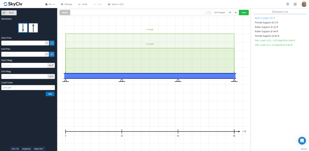
Figura 1: Modelo de viga com cargas permanentes e vivas aplicadas
Depois de resolver o feixe, podemos verificar os resultados, como o diagrama de flexão, para obter seus valores máximos ao longo do comprimento do elemento. As imagens a seguir mostram o resultado final.
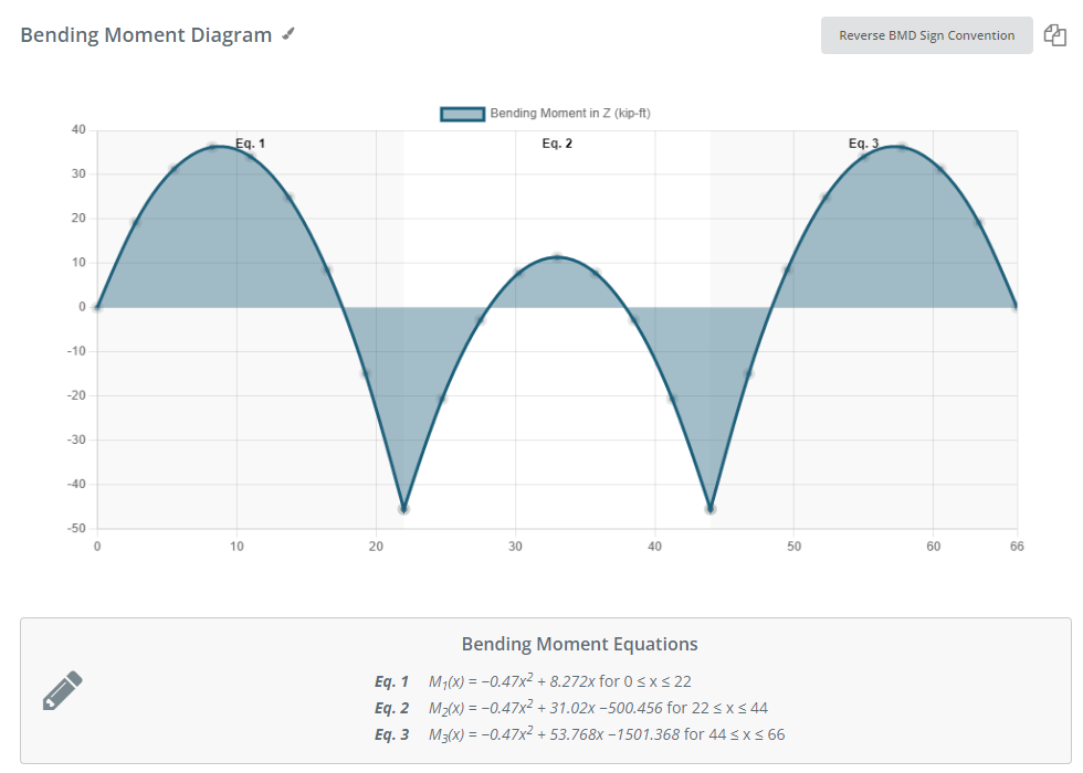
Figura 2: Diagrama de momento fletor devido à combinação de carga especificada
O SkyCiv Beam Software nos fornece uma tabela com os valores máximos de forças, esforços, e deslocamento:
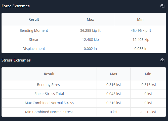
Figura 3: Tabela de resumo
Agora é a hora de selecionar a guia de projeto e selecionar e definir a entrada como layout de armadura, seções de análise, alguns coeficientes, combinações de carga, etc. Veja os números 4 e 5 para mais descrição.
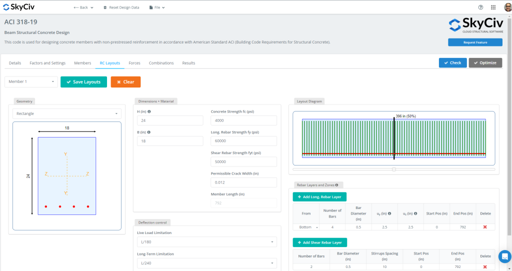
Figura 4: Layouts de feixe RC
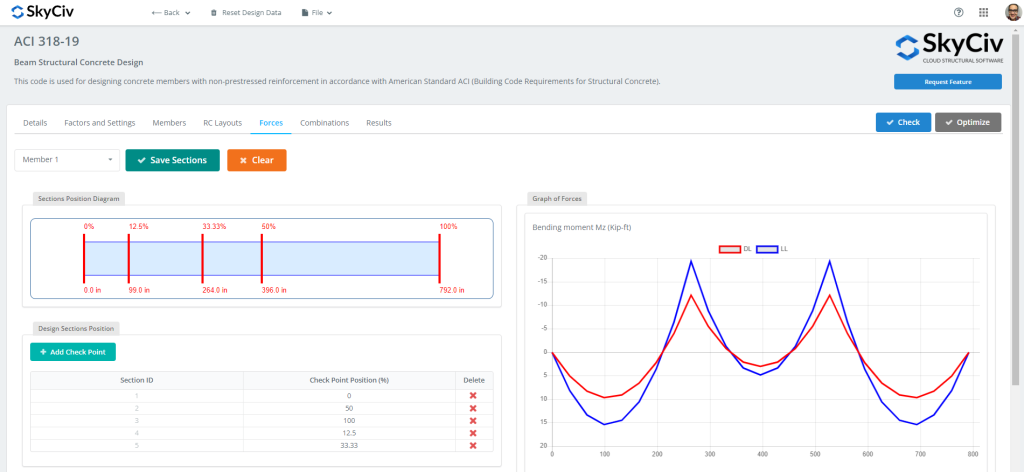
Figura 5: Forças e seções a serem avaliadas no projeto
Assim que todos os dados estiverem prontos, podemos clicar no “Verificar” botão. Esta ação nos dará então os resultados e os índices de capacidade de resistência e facilidade de manutenção.
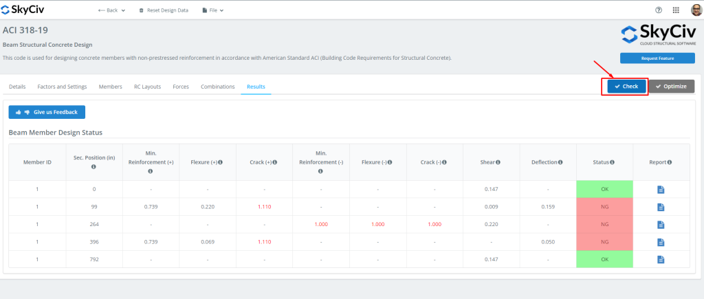
Figura 6: Resultados do projeto do módulo de viga.
Você pode então baixar todos os relatórios necessários para!
Se você é novo no SkyCiv, Inscreva-se e teste você mesmo o software!
SkyCiv Structural 3D
Agora é a hora de usar o 3D Estrutural! Recomendamos apenas retornar ao software beam e clicar no botão “Abrir em S3D” botão. Isso nos ajudará a preparar o modelo e suas entradas em S3D.
Assim que clicamos no botão alterar, o modelo foi criado automaticamente. Lembre-se de salvá-lo! (Se você precisa se familiarizar com este módulo, olha isso link do tutorial!)
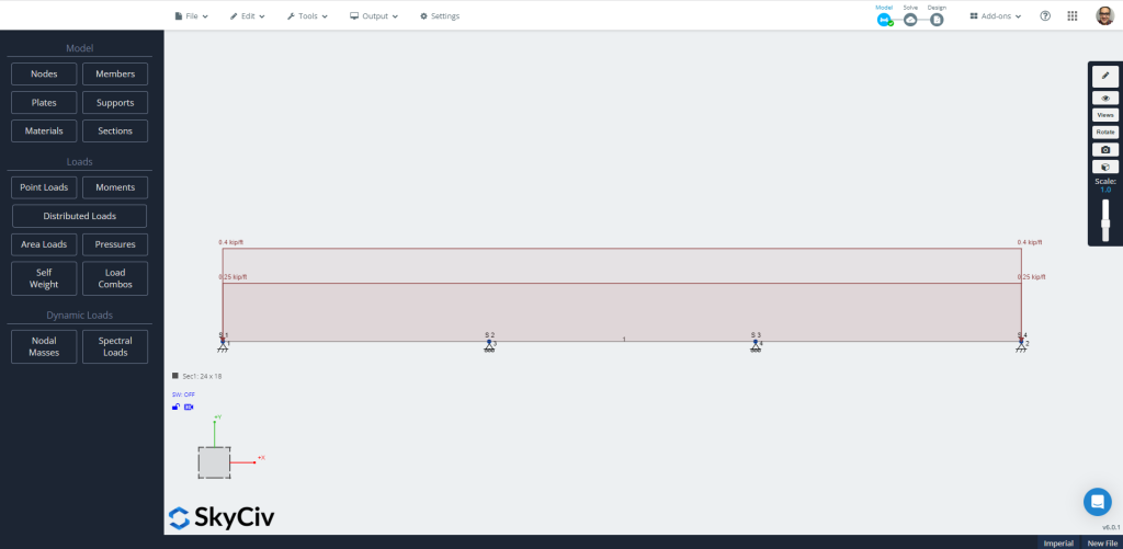
Figura 7: Modelo criado automaticamente em S3D.
Agora vá diretamente para o “Resolver” ícone escolhendo o “Análise linear” Selecione os membros que você deseja repetir. Sinta-se à vontade para verificar e comparar os resultados; vamos usar o “Projeto” Selecione os membros que você deseja repetir. É hora de definir todas as características necessárias para avaliar a viga nas diferentes abas.
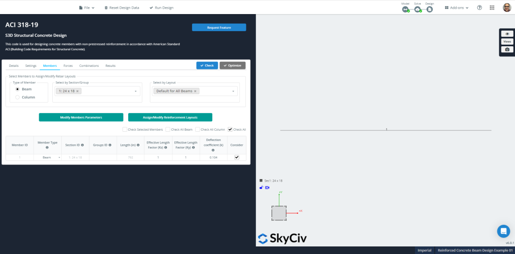
Figura 8: Membros’ informações para projeto
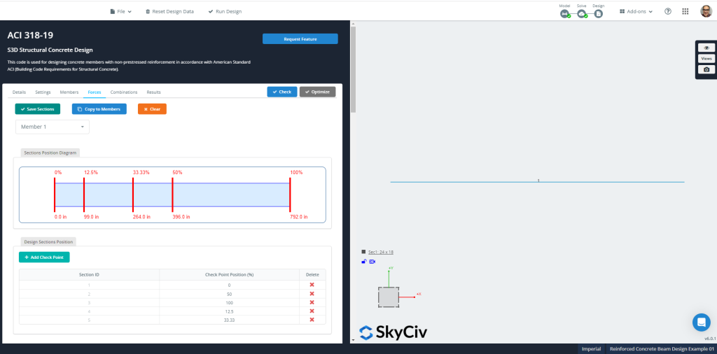
Figura 9: Membros’ forças e seções para projeto
SkyCiv pode verificar um layout RC definido específico ou calcular uma otimização de reforço de seção. Gostaríamos de sugerir que você execute esta última opção.
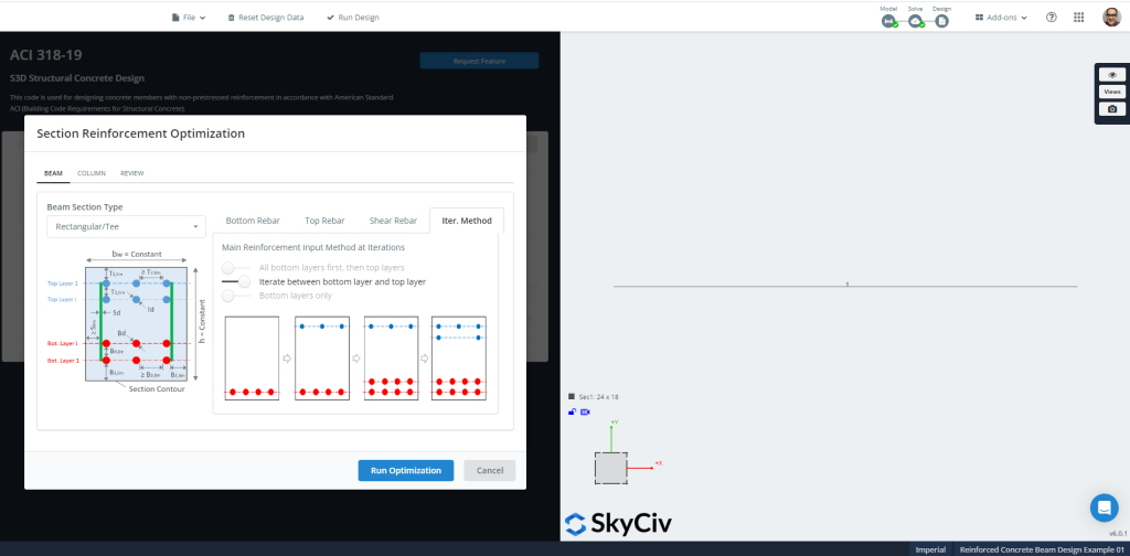
Figura 10: Otimização do Reforço de Seção.
Figuras 11 e 12 mostrar o resultado final e a armadura de seção sugerida calculada para o dimensionamento de otimização.
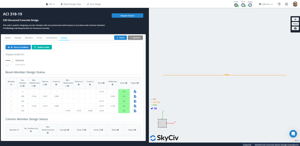
Figura 11: Resultados do projeto de concreto estrutural
Você pode então baixar todos os relatórios necessários para!
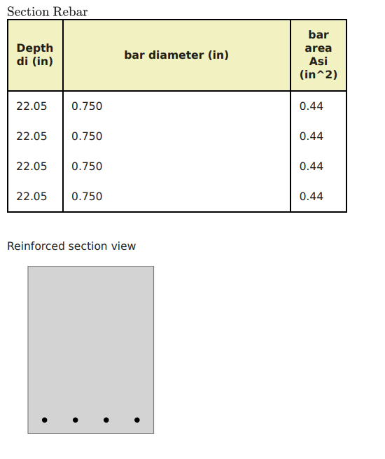
Figura 12: Otimização em Aço de Reforço de Seção
Se você é novo no SkyCiv, Inscreva-se e teste você mesmo o software!
Equações aproximadas ACI-318
Ao projetar uma viga contínua, ACI-318 permite o uso de coeficientes de momento para cálculos de flexão. (Para mais exemplos, sinta-se à vontade para visitar estes artigos do SkyCiv sobre Isso é feito para verificar as equações que são formadas a partir do ACI)
Os momentos nas seções críticas são calculados com: \( M_u = coeficiente vezes w_u vezes l_n^2 \). Onde o coeficiente pode ser obtido a partir do seguinte:
- Vão exterior:
- Exterior negativo: \(\fratura{1}{16}\)
- Meio vão positivo: \(\fratura{1}{14}\)
- Interior negativo:\(\fratura{1}{10}\)
- Vão interior:
- Negativo: \(\fratura{1}{11}\)
- Meio vão positivo: \(\fratura{1}{16}\)
Selecionaremos dois casos: o valor máximo absoluto para momentos fletores positivos e negativos.
\(wu=1,2vezes D + 1.6\vezes L = 1.2 \vezes 0.25 + 1.6 \vezes 0.4 = 0.94 \fratura{kip}{ft} \)
\(M_{você,negativo} = {\fratura{1}{10}}{\vezes 0.94 {\fratura{kip}{ft}}}{\vezes {(22 ft)}^ 2} = 45.50 {kip}{ft} \)
\(M_{você,posição} = {\fratura{1}{14}}{\vezes 0.94 {\fratura{kip}{ft}}}{\vezes {(22 ft)}^ 2} = 32.50 {kip}{ft} \)
Cálculo da resistência à flexão para momento negativo, \({M_{você,negativo} = 45.50 {kip}{ft}}\)
- Seção controlada por tensão assumida. \({\phi_f = 0.9}\)
- Largura do feixe, \({b = 18 pol.}\)
- Área de reforço de aço, \({A_s = frac{M_u}{\phi_fvezes 0,9dvezes fy}= frac{45.50 kip-ft vezes 12 em pés }{0.9\vezes 0.9(17 no )\vezes 60 ksi}=0,66 {no}^ 2}\)
- \({\rho_{min} = 0.003162}\). Área mínima de reforço de aço, \({UMA_{s,min}=rho_{min}\vezes bvezes d = 0.003162 \vezes 18 em vezes 17 em =0,968 {no}^ 2}\). Agora, verifique se a seção está se comportando como tensão controlada.
- \({a = frac{A_svezes f_y}{0.85\vezes f'cvezes b} = frac{0.968 {no}^2vezes 60 ksi}{0.85\vezes 4 ksivezes 18 no }= 0.95 no}\)
- \({c = frac{uma}{\beta_1}= frac{0.95 no}{0.85} = 1.12 no }\)
- \({\varepsilon_t = (\fratura{0.003}{c})\vezes {(d – c)} = (\fratura{0.003}{1.12 no})\vezes {(17no – 1.12 no)} = 0.0425 > 0.005 }\) OK!, é uma seção controlada por tensão!.
Cálculo da resistência à flexão para momento positivo, \({M_{você,posição} = 32.50 {kip}{ft}}\)
- Seção controlada por tensão assumida. \({\phi_f = 0.9}\)
- Largura do feixe, \({b = 18 pol.}\)
- Área de reforço de aço, \({A_s = frac{M_u}{\phi_fvezes 0,9dvezes fy}= frac{32.50 kip-ft vezes 12 em pés }{0.9\vezes 0.9(17 no )\vezes 60 ksi}=0,472 {no}^ 2}\)
- \({\rho_{min} = 0.003162}\). Área mínima de reforço de aço, \({UMA_{s,min}=rho_{min}\vezes bvezes d = 0.003162 \vezes 18 em vezes 17 em =0,968 {no}^ 2}\). Agora, verifique se a seção está se comportando como tensão controlada.
- \({a = frac{A_svezes f_y}{0.85\vezes f'cvezes b} = frac{0.968 {no}^2vezes 60 ksi}{0.85\vezes 4 ksivezes 18 no }= 0.95 no}\)
- \({c = frac{uma}{\beta_1}= frac{0.95 no}{0.85} = 1.12 no }\)
- \({\varepsilon_t = (\fratura{0.003}{c})\vezes {(d – c)} = (\fratura{0.003}{1.12 no})\vezes {(17no – 1.12 no)} = 0.0425 > 0.005 }\) OK!, é uma seção controlada por tensão!.
Finalmente, podemos ver isso em ambos os momentos, negativo e positivo, o resultado é atribuir uma armadura de flexão mínima. A área necessária do vergalhão de aço é igual \(0.968 {no}^2).
Tutoriais Relacionados
Se você é novo no SkyCiv, Inscreva-se e teste você mesmo o software!