Uma introdução às capacidades de análise e projeto de uma estrutura de ponte para a competição AISC Student Steel Bridge
Quase o ano todo, universidades nos Estados Unidos abrigam suas respectivas equipes AISC Student Steel Bridge e clubes que competem no Competição AISC Student Steel Bridge. Isso envolve uma jornada de um ano acadêmico projetando e construindo uma ponte em escala de modelo que é testada sob várias condições de carga e outros critérios de julgamento. Para os alunos, este processo inclui tudo, desde a arrecadação de fundos e o projeto preliminar da ponte, ao pedido, fabricação e montagem da ponte. Patrocinado e facilitado pela AISC, o Student Steel Bridge Competition oferece aos alunos uma sensação de aquisição de engenharia no mundo real, projetar e revisar processos.
Um aspecto muito importante do processo – você poderia dizer mais relevante para o trabalho de pós-graduação – é a análise e modelagem da estrutura da ponte. O software de engenharia estrutural desempenha um papel importante, fornecendo aos alunos o poder de analisar e tomar decisões rapidamente em seus projetos de pontes durante todo o processo de projeto..
O SkyCiv Structural 3D oferece aos alunos a combinação perfeita de poder analítico e adaptabilidade. O SkyCiv se orgulha do tempo reduzido de inicialização necessário para aprender o software e operá-lo com eficiência, levando a mais tempo adicionando valor para seus projetos, e mais cedo também.
então precisamos de algo pequeno e gerenciável como um projeto de exemplo para que você possa obter uma vitória rápida em seu currículo, vamos dar uma olhada em um projeto preliminar de uma estrutura de ponte para a competição AISC Student Steel Bridge.
Modelando a estrutura treliçada
Usando os documentos de restrição do envelope da ponte fornecidos pelo AISC no AISC Student Steel Bridge – 2019 aisc, aisc:
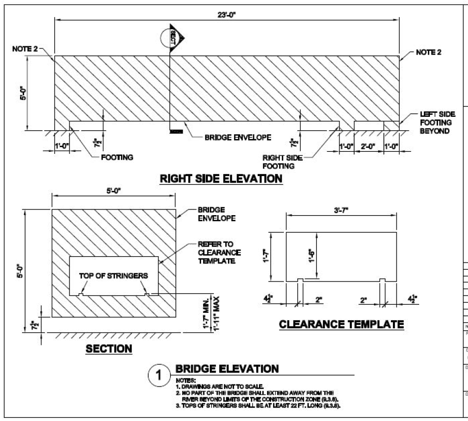
Figura 1: Desenho do envelope da ponte de aço do aluno AISC
(Fonte: Concurso de Pontes de Aço para Estudantes da AISC 2019 aisc)
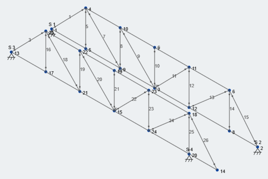
aisc. Clique nos links para obter mais informações sobre Tipos de treliça e Modelando uma treliça. Vamos analisar as longarinas como um único membro para simplificar nosso modelo nesta etapa. Longarinas mais complexas podem ser facilmente modeladas à medida que os alunos avançam no processo de design.
Olhando para a seção da ponte, assumiremos que o nível do solo é a elevação Y de 0, e o centróide da nossa longarina passa por uma elevação Y de 1 pé. Olhando para a elevação lateral, vamos assumir que nossos suportes estão centralizados em cada um dos 1′-0″ locais de pé largo. Isso nos daria um comprimento de longarina inferior de 22 pés. Para a longarina superior da nossa treliça de ponte, digamos que seu centróide passe pela elevação Y de 4.75 ft. Finalmente, assumiremos que existem seis espaços iguais entre as extremidades de nossas longarinas inferiores, então nosso espaçamento de localização de conexão de treliça é 22 pés/6 = 3.67 ft.
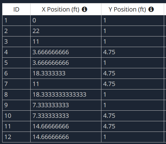
Agora que temos as dimensões gerais, nosso envelope de ponte, vamos criar os nós. Aqui está nossa tabela de nós, com a direção X sendo a dimensão longa para a treliça e a direção Y sendo a elevação.
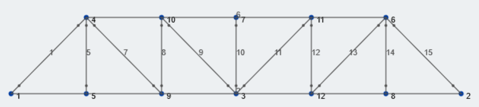
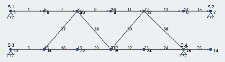
Subseqüentemente, permite desenhar membros entre esses nós com o padrão de treliça Pratt. Certifique-se de selecionar o “Truss” botão na janela esquerda ao criar membros para que as extremidades dos membros sejam liberadas no momento. Aqui está nossa treliça Pratt:
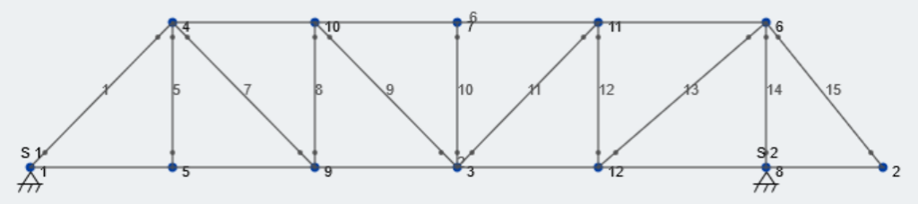
Agora vamos adicionar alguns suportes. Dando outra olhada no desenho AISC Bridge Envelope, o pé direito está localizado dentro do final da ponte, criando um cantilever. Para acomodar isso, vamos mover o nó 6 e Nó 8 para alinhar com a localização deste suporte; O centro da sapata é 3′-0″ para dentro do passeio certo, então nossa dimensão X será 19 pés. Finalmente, permite adicionar suportes de pinos em N0de 1 e Nó 8. Dê uma olhada em nossa treliça atualizada:
A continuação, vamos repetir nossa estrutura de treliça em toda a largura da ponte. Isso pode ser feito selecionando toda a estrutura, incluindo nós e suportes, e indo para Editar – Duplicado. Olhando novamente para a figura 1, assumiremos que as treliças serão centralizadas dentro de cada lado do envelope da ponte. Portanto, eles serão espaçados em 4′- 3 1/2″, ou 4.22 ft, esta é a nossa dimensão de duplicação. Também precisamos ajustar os suportes conforme observado na Figura 1, a treliça esquerda tem seu suporte no final da ponte. Depois de duplicar nossa estrutura de treliça no eixo lateral (Eixo Z), nossa estrutura 3D agora se parece com isso:
Agora, precisamos conectar nossa estrutura usando contraventamento lateral para concluir a modelagem preliminar de nossa estrutura de ponte. Esta parte do design é um processo iterativo para os alunos; eles tentarão descobrir os pontos corretos para conectar cada treliça para minimizar a oscilação lateral, a principal métrica julgada durante o Caso de Carga Lateral. Vamos colocar algum reforço diagonal entre as longarinas superior e inferior das treliças. Por exemplo, como mostrado na vista superior:
A modelagem no módulo Structural 3D do SkyCiv é extremamente intuitiva e leva a análises mais rápidas e resultados mais simples. Dê aos seus alunos uma tentativa de modelar uma treliça em 2D usando nosso Ferramenta gratuita Truss Design Calculator.
Aplicando cargas à nossa ponte
Depois da modelagem, agora podemos começar a aplicar as cargas definidas pelo AISC. Existem dois tipos de carga de cargas, ou casos de carga, que a ponte será testada: Lateral e Vertical. As magnitudes de cada caso de carga são dadas por AISC, mas sua localização exata ao longo do comprimento da ponte não é. Portanto, os alunos precisarão analisar vários locais diferentes para cada caso de carga para descobrir o pior cenário para cada caso. Deve-se notar que cada caso de carga é aplicado independentemente; a estrutura não vê as duas situações de carregamento ao mesmo tempo.
Porque as cargas que são fornecidas pelo AISC são REAL cargas que serão utilizadas na competição, podemos assumir que são cargas de serviço. Estamos tentando projetar esta ponte o mais leve possível enquanto ainda atendemos aos critérios de deflexão. Portanto, nossas combinações de carga não incluirão nenhum fator de carga de amplificação.
Caso de Carga Lateral
Para o Caso de Carga Lateral, vamos olhar para o desenho de carga fornecido pelo AISC no 2019 aisc (Figura 2):
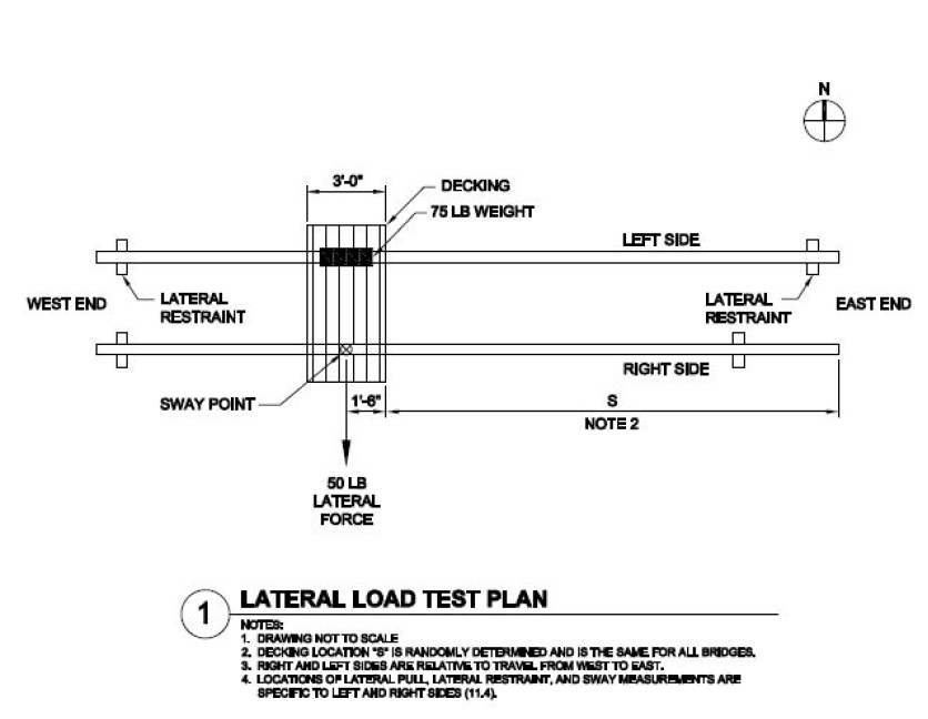
Figura 2: Plano de Teste de Carga Lateral para Competição de Ponte de Aço para Estudantes AISC
(Fonte: Concurso de Pontes de Aço para Estudantes da AISC 2019 aisc)
Primeiro, você percebe que não só existe um 50 libra de força lateral no lado do passeio, mas existe um 75 libra de carga vertical no lado esquerdo no mesmo local relativo ao longo do comprimento da ponte. Segundo, Observação 2 afirma que o local “S” é determinado aleatoriamente. durante o teste, AISC usando grade/decking de metal para suportar o peso, bem como um ponto de ancoragem para a força lateral:
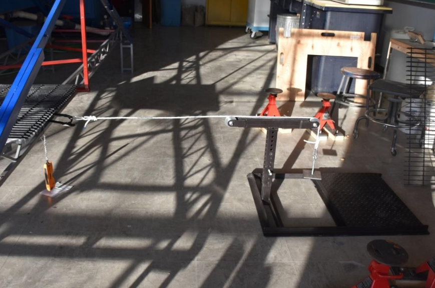
Fonte: Guia de Competição AISC para Participantes
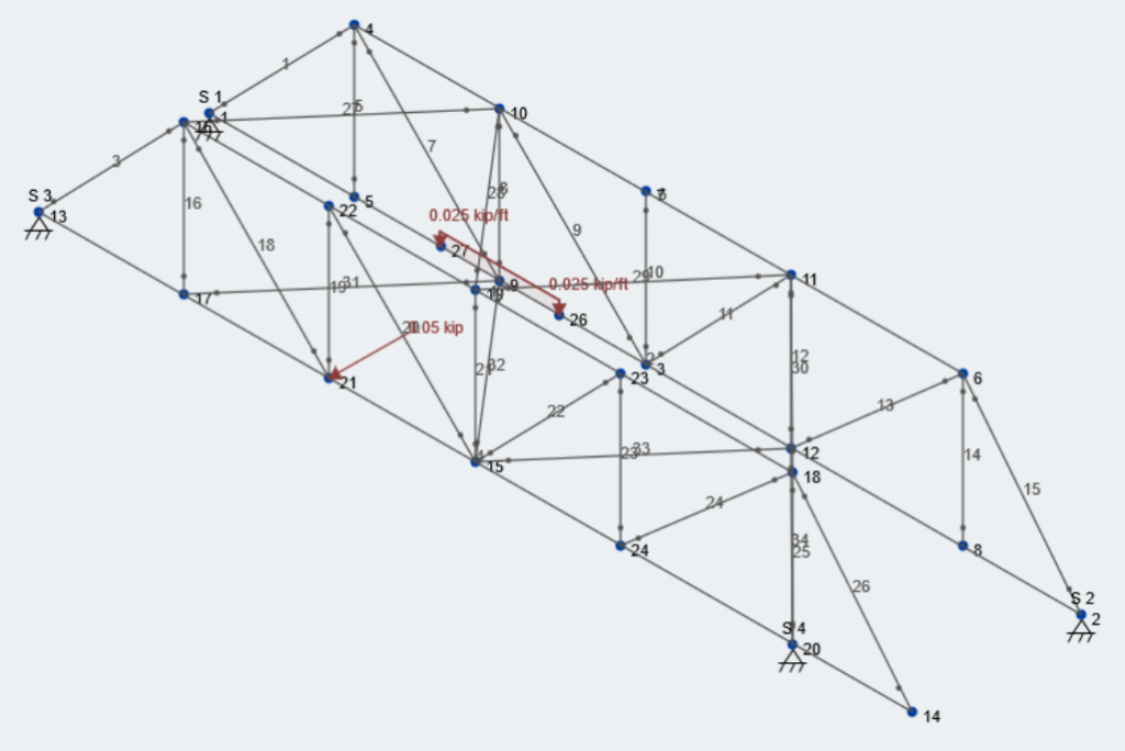
Para este exemplo, vamos aplicar o 50 lb carga lateral no “Nó 21″ do nosso modelo. A 75 lb carga vertical no lado oposto será aplicada como uma carga uniformemente distribuída ao longo dos 3′-0” largura do deck.
\([object Window]:Carregar = 50\:lb = 0.05\:kip)
\(Vertical:Load=75\:lb/3\:ft = 25\:lb / ft = 0.025\:kip/ft\)
Como mencionado anteriormente, são cargas de serviço, então ambas as cargas ocorrerão sob o caso de carga que criamos chamado “Caso de Carga Lateral” e será considerado Digitar. A combinação de carga subsequente será LC #1 e é o seguinte:
\(LC\:1=1.0*Self\:Weight\:of\:Estrutura + 1.0*[object Window]:Load\:Case\)
Novamente, os alunos precisarão aplicar a carga lateral e vertical em vários locais ao longo do comprimento da ponte para descobrir o local que fornece os resultados da análise governamental. Aqui está como nosso modelo se parece com essas cargas aplicadas:
Caso de Carga Vertical
Para o Caso de Carga Vertical, vamos olhar para o desenho de carga fornecido pelo AISC no 2019 aisc (Figura 2):
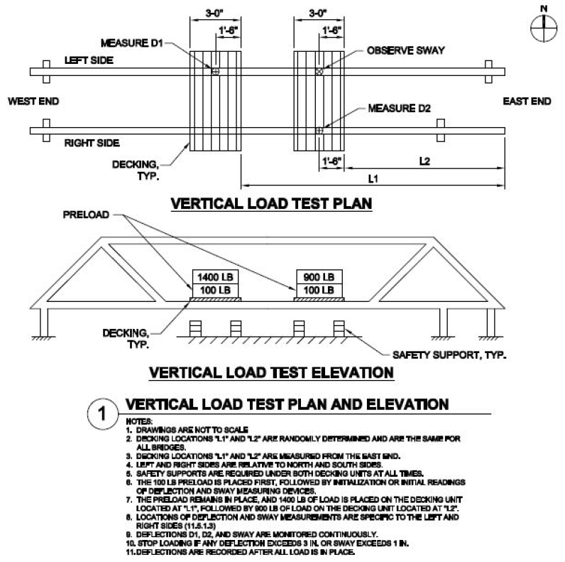
Figura 3: Plano de Teste de Carga Vertical para Competição de Ponte de Aço Estudantil AISC
(Fonte: Concurso de Pontes de Aço para Estudantes da AISC 2019 aisc)
Semelhante ao caso de carga lateral, os locais onde as cargas verticais atuam não são diretamente indicados. Desta vez, há dois casos de carregamento separados que precisamos avaliar. Primeiro, existe o 100 lb condição de pré-carregamento. Então, o adicional 1400 e 900 lbs são adicionados para igualar a um 1500 e 1000 lb carga respectivamente, como mostrado na figura 3. Vamos assumir que as cargas são transportadas uniformemente entre as treliças, e que eles agem como uma carga uniformemente distribuída ao longo do comprimento do estrado. Além disso, identificaremos todas as cargas verticais como Digitar.
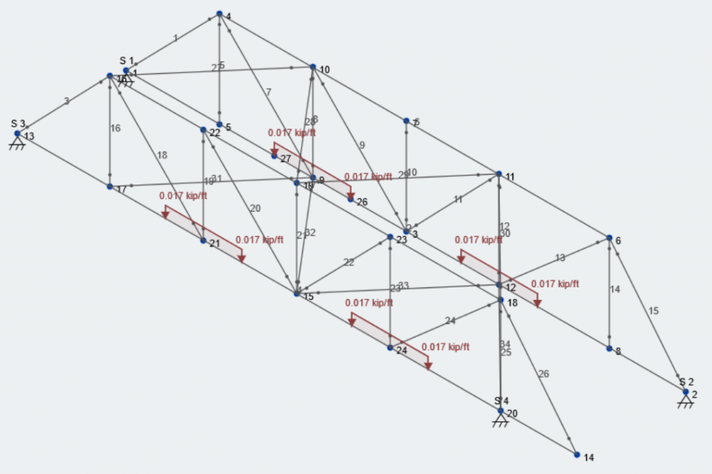
O pré-carregamento será um caso de carga próprio e será chamado “Caso de Carga Vertical – Pré-carga”. Vamos aplicar as cargas distribuídas centradas no nó 21/9 e Nó 24/12. Nó 24 e 12 são espelhados no centro da ponte.
\(Pré-carga = (100\:lb / 2)/3\:ft = 16.7\:lb / ft = 0.0167\:lb/ft)
Subseqüentemente, sendo a combinação de carga:
\(LC\:2=1.0*Self\:Weight\:of\:Estrutura + 1.0*Vertical:Load\:Case-Preload\)
Aqui está a aparência do nosso modelo com a caixa de pré-carregamento:
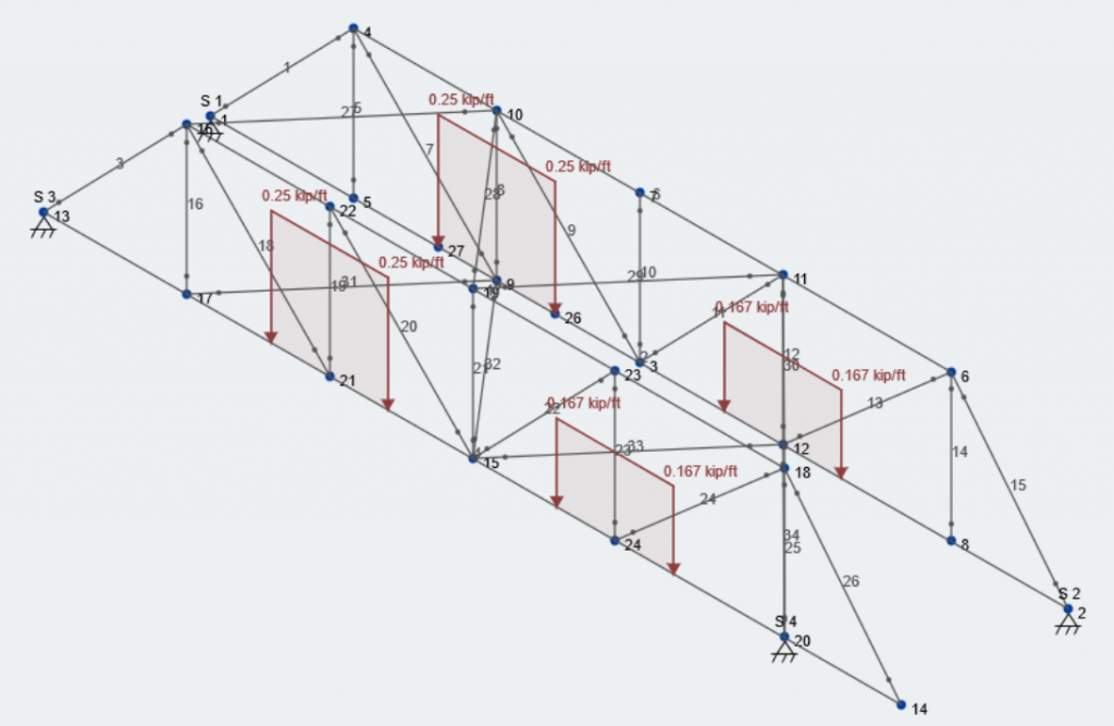
Agora, vamos adicionar a carga restante. No lado esquerdo, a carga total é agora 1500 Libra, e do lado direito está agora 1000 Libra. Vamos salvar isso como outro caso de carga chamado “Caso de Carga Vertical – Total”.
\(Total\:Load\:on\:Left\:Side\: = (1500\:lb / 2)/3\:ft = 250\:lb / ft = 0.25\:kip/ft\)
\(Total\:Load\:on\:Right\:Side\: = (1000\:lb / 2)/3\:ft = 167\:lb / ft = 0.167\:kip/ft\)
Nossa última combinação de carga é, portanto, identificada como:
\(LC\:3=1.0*Self\:Weight\:of\:Estrutura + 1.0*Vertical:Load\:Total\)
Aqui está a aparência do nosso modelo com a carga total aplicada no caso de carga vertical:
Veja abaixo uma foto de uma competição recente e o mecanismo de carregamento para o caso de carga vertical:
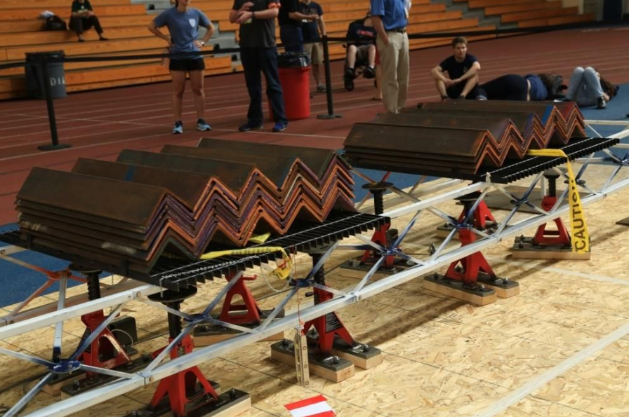
Fonte: Guia de Competição AISC para Participantes
Análise de Casos/Combinações de Carga
A última parte deste exercício é executar a análise em nossa estrutura de ponte e interpretar os resultados. Antes de fazermos isso, vamos dar uma olhada nas combinações de carga e seus fatores de carga:

Essas cargas são cargas de serviço, portanto, usaremos um fator de carga de 1.0 em todos eles. Essas três combinações de carga encapsulam as condições de carga apresentadas entre o Caso de Carga Lateral e o Caso de Carga Vertical, fornecido pela AISC. Agora, vamos fazer nossa análise. Antes de carregar sua estrutura, veremos os resultados axiais para a treliça direita com a extremidade em balanço para LC 3.
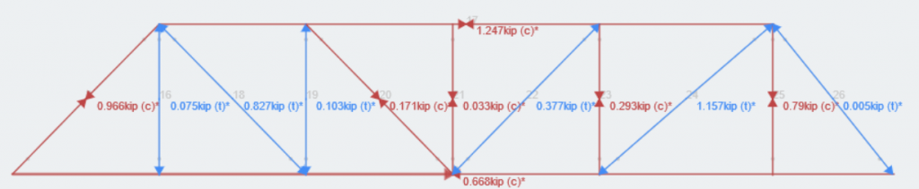
SkyCiv dá aos usuários o poder de se esconder, isolam e visualizam os resultados de suas estruturas da maneira que acharem adequada. Observe toda a estrutura para uma ideia mais global, ou isolar combinações ou membros únicos para avaliar em um nível mais granular. Daqui, os alunos precisarão passar pelo processo iterativo de design e colaboração com sua equipe. Os alunos agora podem se concentrar em se tornar engenheiros melhores e bem preparados não apenas para a competição AISC Student Steel Bridge, mas como Engenheiro em Treinamento e Engenheiro Profissional.
Este exemplo mostra como o SkyCiv 3D pode ser poderoso e simples, com seus módulos intuitivos voltados para usuários que vão desde estudantes de engenharia do primeiro ano até engenheiros principais no auge de suas carreiras. SkyCiv espera que possa ser uma ferramenta de destaque para uso em sala de aula, permitindo que os alunos se concentrem em aprender sobre engenharia em vez de aprender sobre o software.
Referências:
- “Programas Universitários”. AISC, 2019, www.aisc.org/education/university-programs/student-steel-bridge-competition/.