
The single plate connection, ou aba de cisalhamento, is one of the simple shear connections set out in Part 10 of the AISC Manual, and a fabricator favourite because it is the cheapest of the group: one plate, one weld line, one bolt group.
A placa é sempre soldada ao suporte e normalmente aparafusado em campo para a viga de conexão. It can be welded to the beam instead on a shop-assembled frame. What you should not do is put that weld in the field: field welding is labour-intensive and expensive next to running a bolt in.
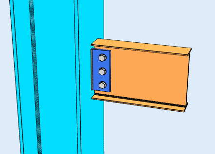
Dois tipos de configuração
Which configuration you are in decides which rules apply, and it follows from the geometry rather than from a setting you choose.
-
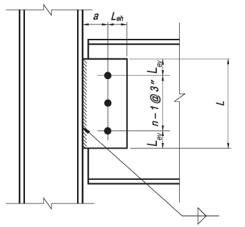
Configuração convencional
- Apenas uma única linha vertical de parafusos é permitida. O número de parafusos na conexão deve estar entre 2 e 12.
- A distância da linha do parafuso à linha de solda deve ser igual ou menor que 3-1/2 no.
- furos padrão (DST) ou orifícios horizontais com fenda curta (HSSL) são permitidos para serem usados conforme observado na Tabela 10-9 da 15ª edição do manual AISC.
- A distância da borda vertical deve satisfazer os requisitos da Tabela J3.4 da Especificação AISC. A distância horizontal da aresta deve ser maior ou igual a 2d tanto para a placa quanto para a alma da viga, onde d é o diâmetro do parafuso.
- Tanto a espessura da placa quanto a espessura da alma da viga devem atender ao requisito de espessura máxima dado na Tabela 10-9 da 15ª edição do manual AISC.

-
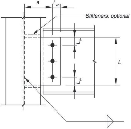
Configuração Estendida
- O número de parafusos não é limitado.
- A distância da linha de solda até a linha do parafuso mais próxima do suporte não é limitada.
- O uso de furos deve atender aos requisitos da Seção J3.2 da Especificação AISC.
- As distâncias das bordas horizontais e verticais devem atender aos requisitos da Tabela de Especificação AISC J3.4.

Designing a Single Plate Connection in SkyCiv
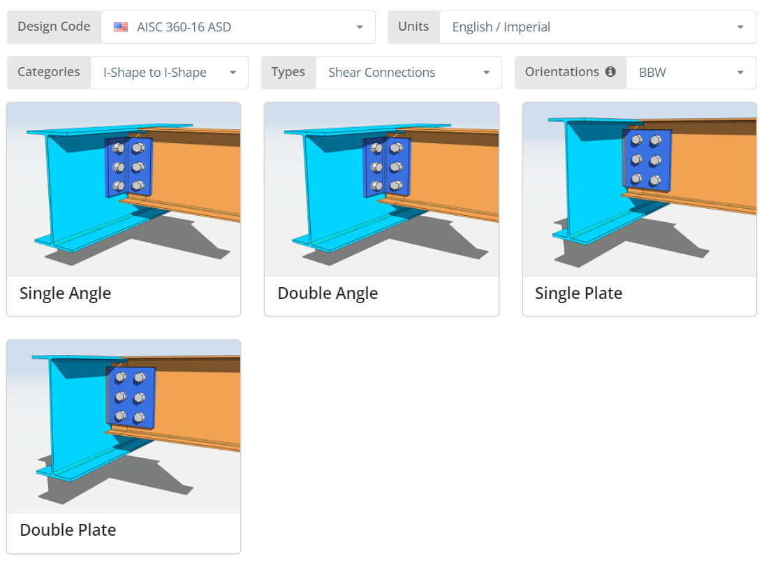
O código de projeto pode ser AISC 360-16 ASD ou LRFD, e unidades inglesas/imperiais ou SI/métricas. Orientation is BCF, BCW ou BBW; hover the tooltip for what each one means. Clique no “Placa Única” telha.
Guia Detalhes
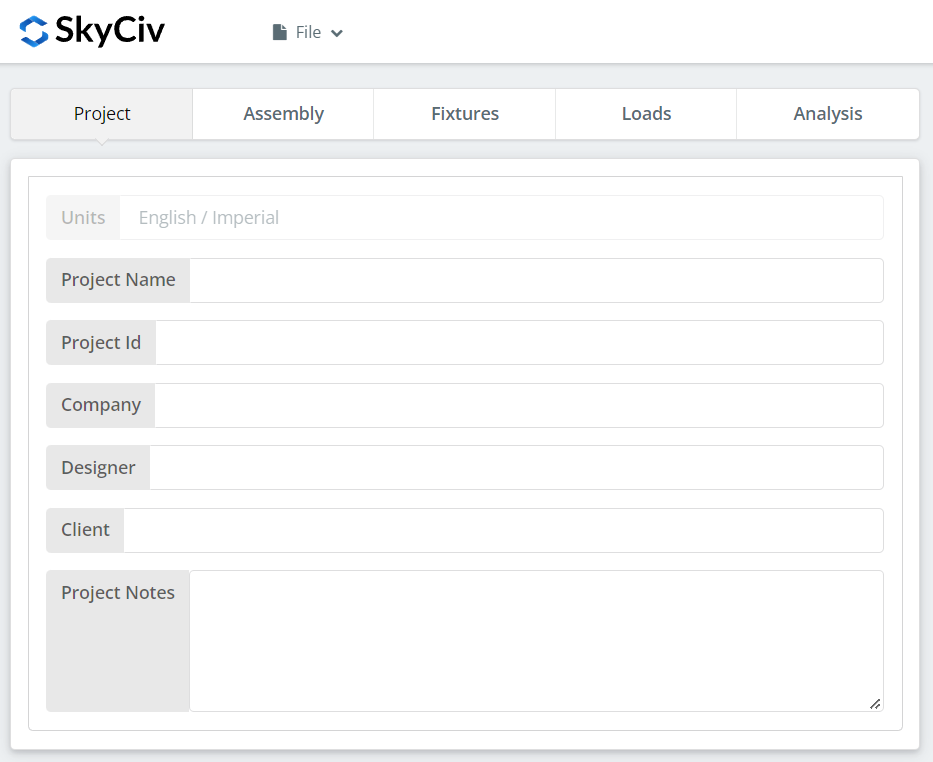
Registre aqui os detalhes do projeto. Nada disso altera os cálculos, mas isso traz para o relatório.
Aba de montagem
Três guias ficam em Assembly: the Girder, o feixe, e a Conexão, which holds the single plate.
Guia Viga
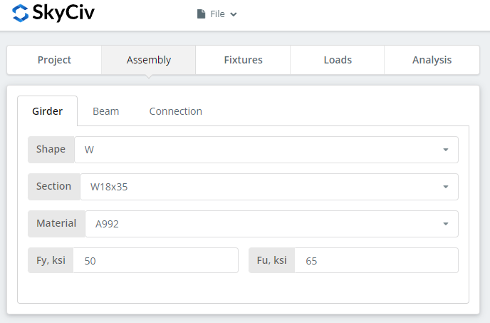
Specify the section and material grade of the supporting member. A992 e A36 estão na lista; para qualquer outra coisa, escolha Personalizado e insira Fy e Fu.
Aba de Feixe
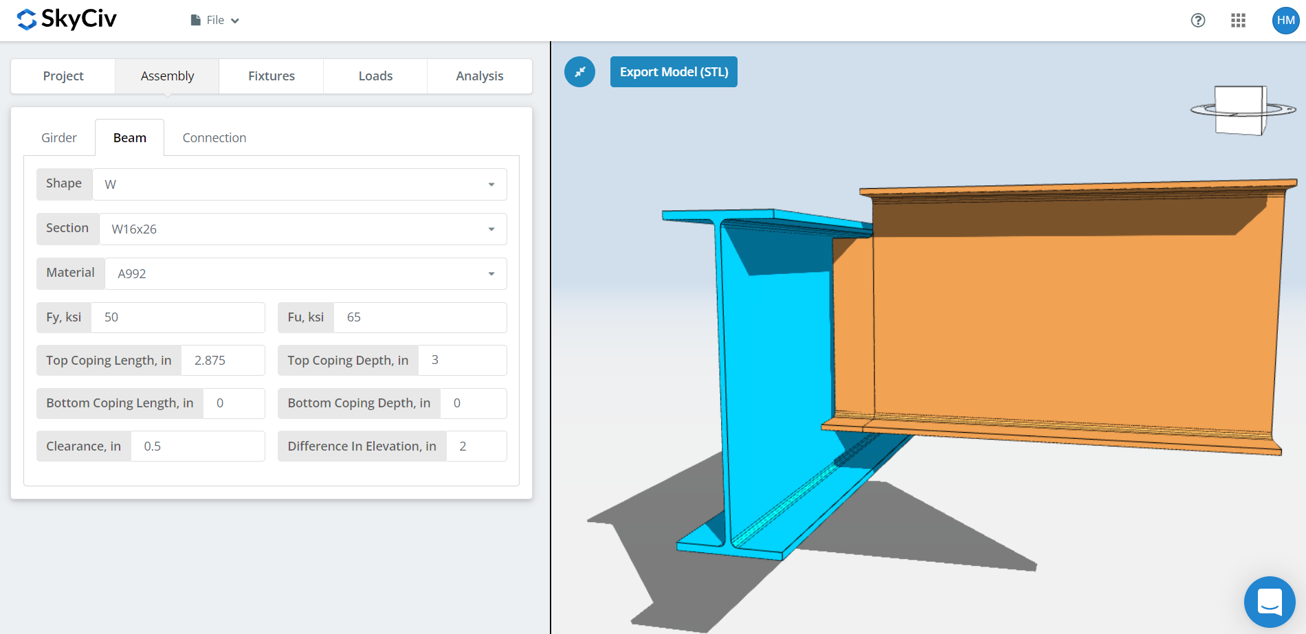
As mesmas entradas para o feixe, plus cope dimensions, beam clearance and the difference in elevation.
For BBW orientation the coping is worked out automatically, and you can override it. The automatic cope recalculates whenever you change the beam section, the girder section, the clearance or the difference in elevation.
The clearance is also what puts you in one configuration or the other. A clearance small enough that the beam still sits inside the girder will usually give a conventional single plate, unless the girder flange is wide enough that the distance from the bolt to the girder web exceeds 3-1/2″. A clearance that puts the beam completely outside the girder flange gives an extended single plate. For the difference in elevation, a positive value means the beam is above the girder and a negative value below.
Aba Conexão
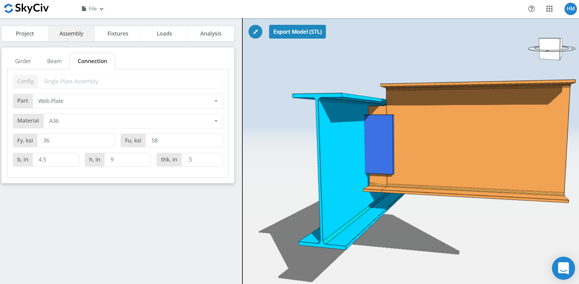
Set the plate properties: grade A36 or A992, ou personalizado com seu próprio Fy e Fu, then the plate width ‘b’, height ‘h’ and thickness ‘thk’.
Watch the 3D renderer as you go. The plate height should sit within the beam depth, and the plate width has to be wide enough for the beam to bolt or weld to, which matters most in an extended configuration.
Luminária 1 Aba
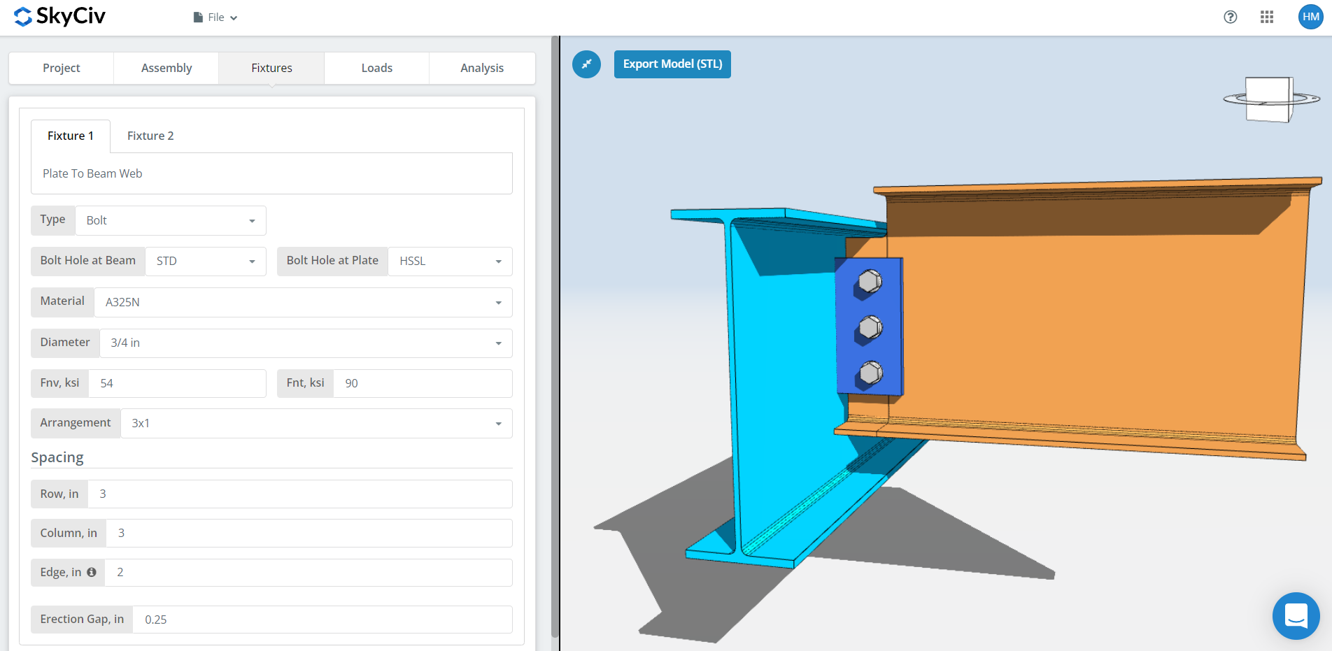
Luminária 1 is the plate to beam web connection. Pode ser parafusado ou soldado; este passo a passo usa aparafusado.
Primeiro, the bolt hole types at the beam and at the plate. Os fabricantes geralmente pedem furos padrão (DST) in the beam and horizontal short-slotted holes (HSSL) in the plate, que compra tolerância adequada no campo. Note that those two are also the only hole types the conventional configuration permits, so reaching for oversized holes moves you into the extended configuration rules.
A continuação, o material ou classe do parafuso: A307, A325, A490 ou personalizado. A325 e A490 são classes dentro da ASTM F3125, que consolidou as especificações independentes mais antigas. Escolha N ou X para uma conexão do tipo rolamento e SC para deslizamento crítico.
As juntas de deslizamento crítico têm menor capacidade de parafuso de projeto do que as do tipo rolamento, então use-os onde o deslizamento realmente importa: furos superdimensionados ou com fenda, reversão de carga, ou fadiga. Entre N e X, X fornece a maior capacidade de cisalhamento do parafuso, mas as roscas devem ser excluídas do plano de cisalhamento, e o montador tem que saber disso. Entre SC(A) e SC(B), SC(B) oferece maior capacidade e requer uma superfície de contato mais cuidadosamente preparada, por exemplo, limpeza por jateamento comercial SSPC-SP6.
Então o diâmetro do parafuso, de 08/05″ para 1-1/2″ ou os equivalentes métricos, e o arranjo, até 12 linhas e colunas de parafuso, com o espaçamento entre linhas e colunas.
Worth knowing: if you need more bolt group capacity, opening up the spacing can do it instead of adding bolts, as long as the plate height still fits within the beam depth. The bolt group strength uses the instantaneous centre of rotation method (ICOR), so a wider spacing is credited with the capacity it actually provides. Check with your fabricator first, no entanto. Many prefer 3″ spacing typical throughout.
A “Beira” entrada é a distância da extremidade da viga até a primeira coluna do parafuso.
Durar, a lacuna de ereção. Esta é a lacuna que permite que a viga seja colocada no local. Custa capacidade, então especifique apenas onde a ereção realmente precisa.
Luminária 2 Aba
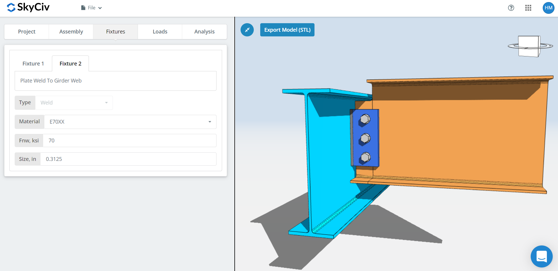
Luminária 2 is the plate to support connection, whether that support is a girder web, a column flange or a column web. For a single plate this is welded only.
Especifique o material de solda, ou ‘Personalizado’ with your own Fnw if the electrode is not listed, então o tamanho da solda. For single plate connections the weld needs to be at least 5/8 vezes a espessura da placa, so that the weld develops the plate.
That rule has a cost consequence worth planning around. Tabela 8-12 da 15ª Edição do Manual AISC, página 8-126, shows a large jump in weld passes between 5/16″ and 3/8″ filé: 5/16″ needs a single pass, 3/8″ needs three. A 1/2″ plate needs only a 5/16″ fillet to develop it, which keeps you in single-pass territory. So if the connection is short of capacity, increase the plate height to the maximum allowable before you increase the thickness. A thicker plate demands a larger weld, and a larger weld means more passes, more deposited metal and more labour time.
Guia de Cargas
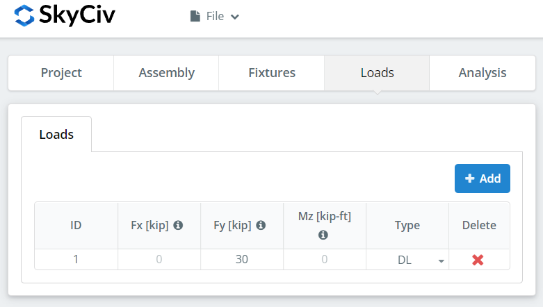
Enter the vertical shear under ‘Fy’.
Match the load to the design method you picked at the start. O LRFD leva cargas fatoradas em relação à resistência do projeto; ASD leva cargas de serviço contra a força permitida. O software não consegue dizer o que você digitou.
Guia Resultados
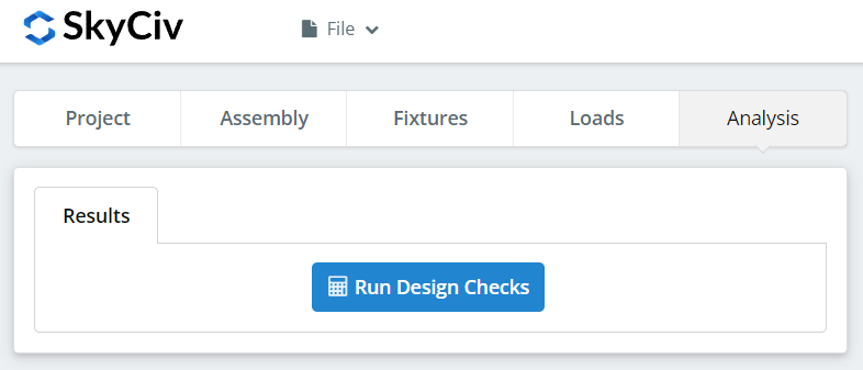
Clique “Executar verificações de design”. Qualquer coisa que esteja faltando nas guias anteriores é sinalizada aqui, em vez de ser padronizada silenciosamente.
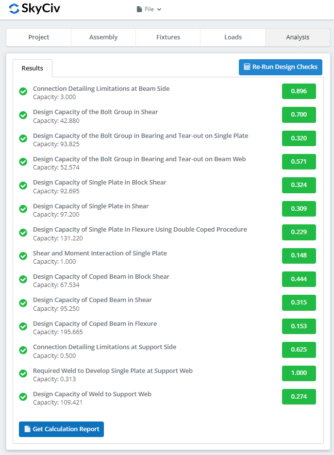
O resumo mostra se a conexão passou, com uma taxa de utilização contra cada cheque. Se falhou, altere as entradas nas guias anteriores e clique em “Executar novamente verificações de design”. Quando isso passa, “Ver relatório de cálculo” abre o relatório detalhado.
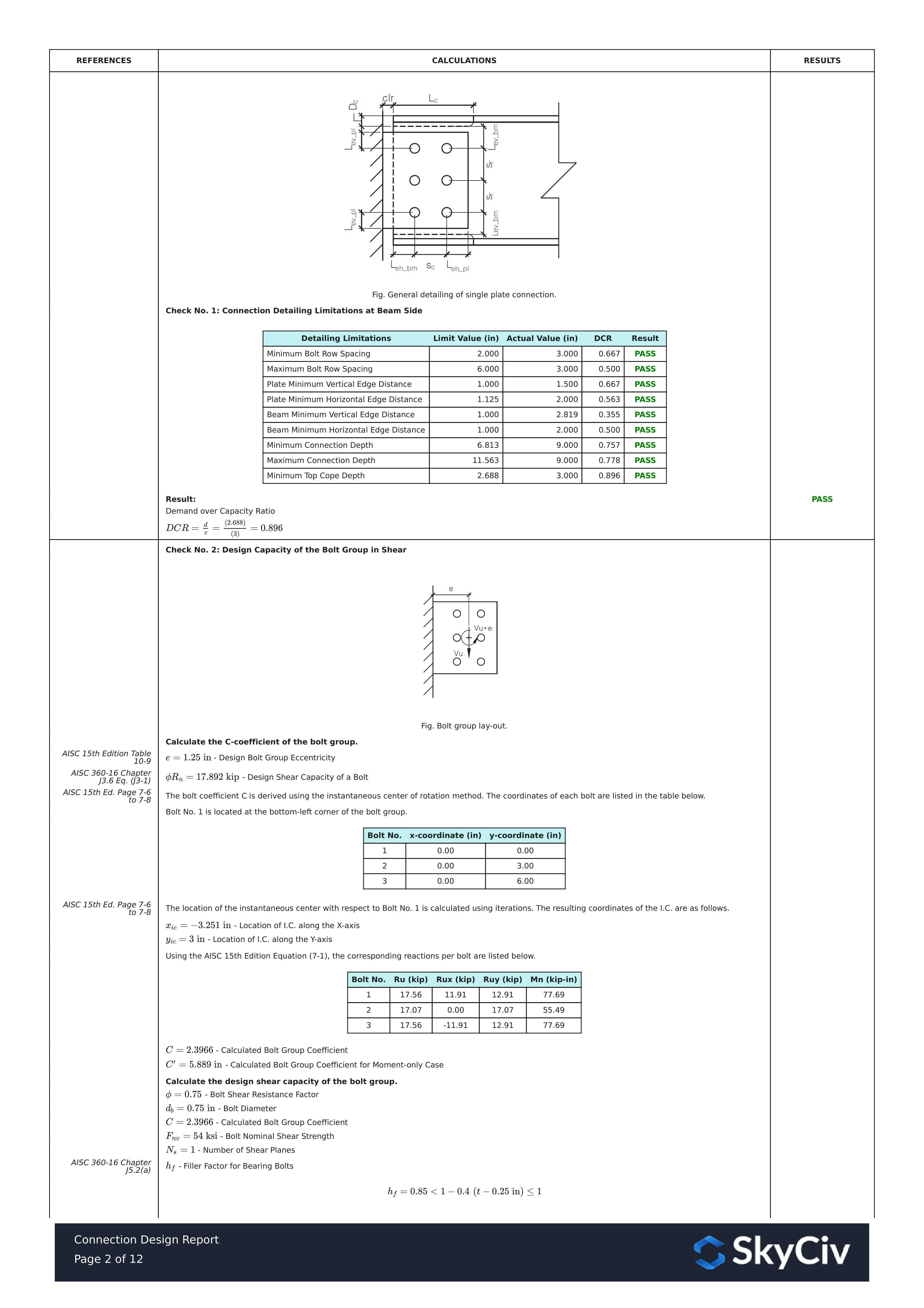
Isso é um extrato do relatório. Cada verificação traz sua referência ao manual ou especificação AISC, e o funcionamento segue a ordem que a especificação usa, para que um engenheiro revisor possa lê-lo linha por linha, em vez de fazer engenharia reversa de um número.
Aqui está uma cópia em PDF do relatório de cálculo detalhado completo: Relatório de Projeto de Conexão.
Experimente você mesmo
Pick the single plate, insira suas seções, plate and shear, e veja cada verificação com sua referência de código. Ele roda no navegador, sem nada para instalar.
Veja também o single plate connection calculator, a double angle calculator, quanto pelo Etapas para projetar visão geral.
