Dimensionamento de barras para estruturas de madeira de acordo com AS 1720 – 2010
Informações gerais
Antes de você começar
Antes de iniciar o módulo de design, você precisará executar as seguintes etapas extras.
- Importar combinações de carga de código de projeto.
- Atribuir casos de carga de código de projeto aos grupos de carga em seu modelo.
Informações específicas do projeto
Suporte para versão atual
Seções
- Retangular
- Circular
Base de dados integrada de secções comuns para madeira serrada, GluLam e LVL.
Materiais
- Madeira serrada, temperado e sem tempero
- GluLam
- Madeira de poste
- LVL (chegando)
Banco de dados integrado de materiais de madeira serrada, GluLam e poste de madeira.
Começando
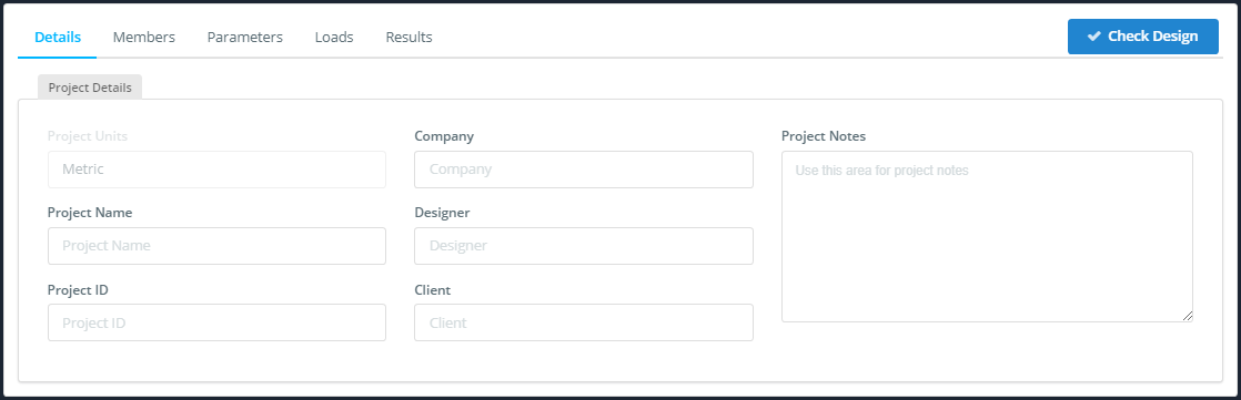
Detalhes
No Detalhes você pode inserir os detalhes do seu projeto para que eles sejam exibidos no seu relatório, no entanto, eles não são obrigatórios.
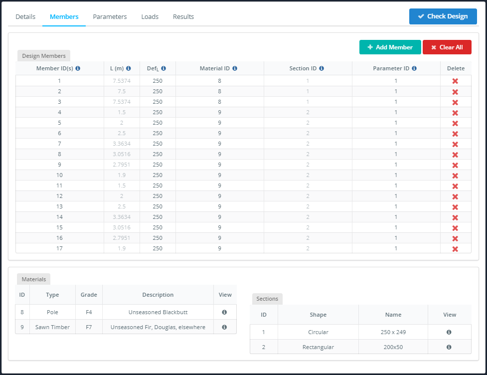
Membros
DEFINIÇÃO: Membro de Design: um membro, ou grupo de membros conectados com a mesma seção e material.
A Membros aba contém diversas tabelas:
- A Membros Design tabela: Veja abaixo.
- A Materiais Tabela: para sua referência para revisar os materiais usados em seu design.
- A Seções Tabela: também para referência.
A Membros Design tabela permite que você adicione, remova e edite o limite de deflexão e os parâmetros dos membros do projeto. Se você estiver usando a versão de integração S3D esta informação será preenchida automaticamente com valores padrão.
No Membros aba você pode editar:
- A ID de membro(s) campo: você pode adicionar vários membros a um único membro de design para simplificar seu design. Insira os IDs dos membros separados por vírgulas.
- A DefL campo: escolha um limite de deflexão apropriado, isso é necessário para calcular a taxa de utilidade de deflexão.
- A ID de parâmetro campo: o ID que vincula seu membro de design ao Parâmetro mesa no Parâmetros aba, leia abaixo para obter mais informações sobre como definir parâmetros.
NOTA: Inserir itens como membros ou nós como uma lista separada por vírgulas é um recurso útil amplamente utilizado no SkyCiv. Por exemplo: ao modelar, você pode aplicar as mesmas cargas a vários membros inserindo uma lista separada por vírgulas dos IDs dos membros no campo ID de membro campo.
Parâmetros
Devido ao número de parâmetros necessários para cálculos no AS 1720, tornamos mais fácil inseri-los criando uma tabela de parâmetros vinculada ao Membros Design tabela. Se você tiver membros de design semelhantes, não será necessário inserir novamente os mesmos parâmetros para cada um deles, basta atribuir a eles o mesmo ID de parâmetro.
A ID de parâmetro está inserido no Membros Design mesa sob o Membros aba, Veja acima.
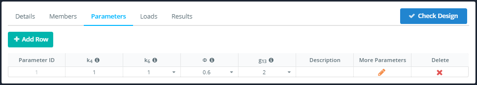
NOTA: A maior parte dos parâmetros foi ocultada – para acessá-los, Clique no editar ícone abaixo Mais parâmetros cabeçalho.
No Parâmetros aba você pode editar:
- A k4 campo: fator de tempero parcial.
- A k6 suspenso: fator de temperatura.
- A A seguir estão as diferentes maneiras de determinar os coeficientes de pressão de terra para calcular a resistência ao atrito unitária de estacas em areia suspenso: fator de capacidade.
- A g13 suspenso: fator de comprimento efetivo.
- A Descrição campo: para sua referência, não aparece no relatório.
Quando a ediçãoícone t é clicado está aberto, você verá que os parâmetros estão agrupados:
- A Restrições Intermediárias aba: para flexão e flambagem por compressão.
- A Pólo aba: para seções circulares.
- A Compartilhamento de força aba: para verificações de flexão em seções retangulares.
- A Tensão aba: para membros aparafusados.
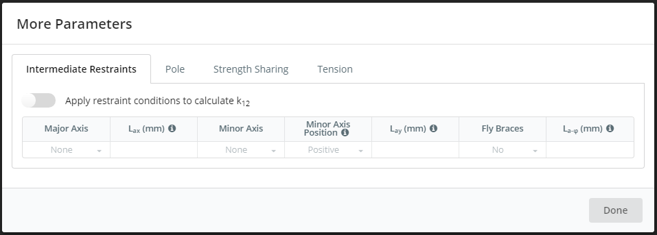
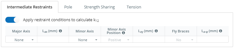
Parâmetros de restrições intermediárias
Se você quiser aplicar esses parâmetros, por favor defina o Aplicar ativar.
No Restrições Intermediárias aba você pode editar:
- A Eixo principal suspenso: tipo de restrição contra flambagem do eixo principal.
- A Lmachado campo: distância entre restrições discretas.
- A Eixo Menor suspenso: tipo de restrição contra encurvadura de eixo menor e encurvadura lateral-torcional.
- A Posição do eixo menor posição suspensa da restrição na seção, positivo se a restrição estiver na borda superior de uma viga normalmente orientada.
- A Lé campo: a distância entre restrições discretas, se o campo Eixo Menor estiver definido como Discreto, isso será obrigatório.
- A Suspensórios para mosca suspenso: restrição parcial contra encurvadura lateral-torcional.
- A La-f campo: A distância entre suportes de mosca.
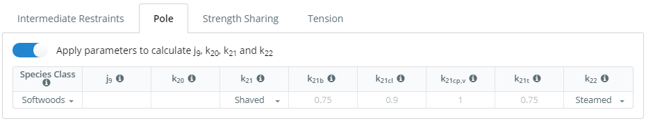
Parâmetros do Pólo
Se você quiser aplicar esses parâmetros, por favor defina o Aplicar ativar.
Nesta aba você pode editar:
- A Classe de Espécies campo: garfo20 e k21, a norma fornece um método para cálculo dos valores para Eucaliptos e Corímbias, e madeira macia. Outras madeiras nobres devem ser estimadas.
- A j9 campo: fator de rigidez de imaturidade.
- A k20 campo: fator de força de imaturidade.
- A k21 suspenso: fator de barbear.
- A k21b, k21cl, k21cp,v, e k21t Campos: fatores de barbear para várias propriedades de resistência.
- A k22 suspenso: tipo de processamento.
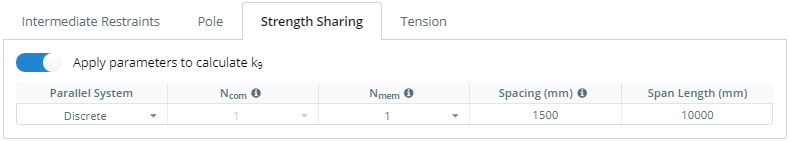
Parâmetros de Compartilhamento de Força
Se você quiser aplicar esses parâmetros, por favor defina o Aplicar ativar.
No Compartilhamento de força aba você pode editar:
- A Sistema Paralelo campo: escolha uma combinação de discreto e combinado.
- A Ncom suspenso: número de elementos combinados em uma unidade discreta.
- A Nmem suspenso: número de unidades discretas do sistema.
- A Espaçamento campo: espaçamento centro a centro de unidades discretas.
- A Comprimento do Vão campo: vão efetivo dos membros paralelos.
Parâmetros de tensão
Se você quiser aplicar esses parâmetros, por favor defina o Aplicar ativar.
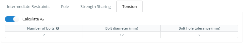
No Tensão aba você pode editar:
- A Número de parafusos campo: número de parafusos na seção transversal crítica.
- A Diâmetro do parafuso campo: diâmetro dos parafusos.
- A Orifício do parafuso campo de tolerância: tolerância.
NOTA: O cálculo de An assume que os parafusos passam pela menor seção transversal e estão uniformemente espaçados. Não leva em conta espaçamento mínimo ou distâncias de borda.
Cargas
Todos os materiais são afetados pela fluência (aumentos lentos e mínimos ao longo do tempo da deformação de um elemento sob carga contínua). A madeira tem um efeito de fluência significativo, ao contrário de outros materiais de construção comuns, como concreto e aço, fluência de madeira é pedidos de magnitude mais. Isto torna o projeto de cargas em estruturas de madeira um pouco mais complicado, a duração da carga precisa ser considerada para cada combinação de carga.
Para contabilizar este efeito AS 1720 fornece um fator para a duração da carga para força (k1) e orientação sobre os fatores apropriados a serem usados para combinações de carga do AS 1170. Eles são preenchidos automaticamente nos parâmetros de combinações de carga com base nas unidades de duração de carga selecionadas.
A Cargas guia contém:
- A Força aba: para combinações de carga de resistência.
- A Facilidade de manutenção aba: para combinações de carga de manutenção.
- A Não alocado aba: combinações de carga definidas pelo usuário podem ser movidas para Força ou Facilidade de manutenção guias.
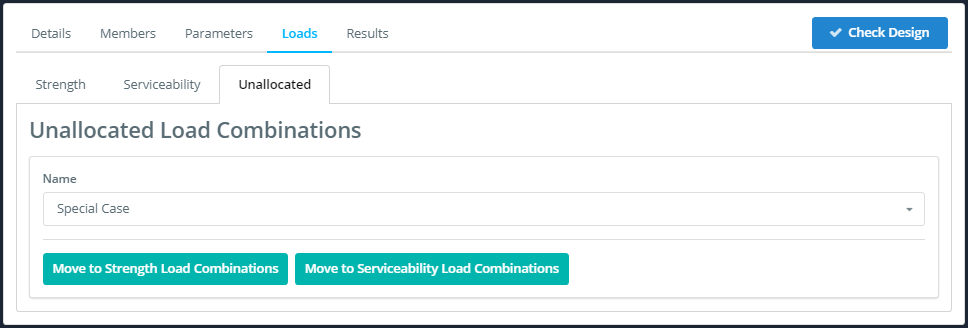
NOTA: Para alocar suas combinações de carga personalizadas, basta clicar no botão do tipo de combinação de carga para a qual você deseja movê-la. Após, revise os fatores de combinação de carga na guia apropriada.
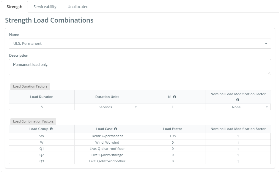
Força
No Força aba você pode editar:
- A Nome suspenso: selecione o nome da combinação de carga a ser exibida.
- A Descrição campo: para referência, não aparece no relatório.
- A Unidades de duração suspenso: segundos, minutos, horas, dias, meses ou décadas, estes correspondem ao k1 tabela de fatores.
- A Fator de modificação de carga nominal suspenso: Nenhum, curto prazo, longo prazo, terremoto, combinação ou personalizado.
- A Fatores de modificação de carga nominal campos para cada grupo de carga: para editar selecione o ‘personalizado’ de Fator de modificação de carga nominal tipo personalizado suspenso, caso contrário, eles serão preenchidos automaticamente com AS 1170 valores.
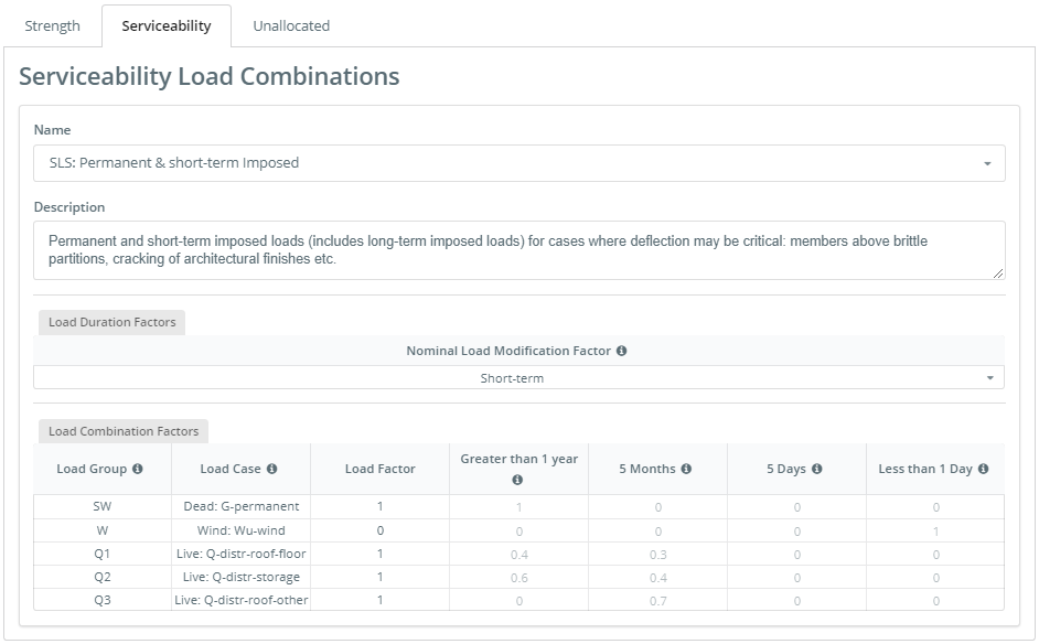
Facilidade de manutenção
No Facilidade de manutenção aba você pode editar:
- A Nome suspenso: selecione o nome da combinação de carga a ser exibida.
- A Descrição: não requerido, não aparece no relatório.
- A Fator de modificação de carga nominal suspenso: Nenhum, curto prazo, longo prazo, terremoto, combinação ou personalizado.
- Os campos no Maior que 1 Ano, 5 Meses, 5 Dias e menos então 1 Dia colunas: esses fatores são proporções do caso de carga que é igual à respectiva duração de carga.
NOTA: Cada proporção de duração da carga fatorial deve ser ≤ 1 e a soma de todas as proporções de duração de carga em cada linha deve ser ≤ 1.
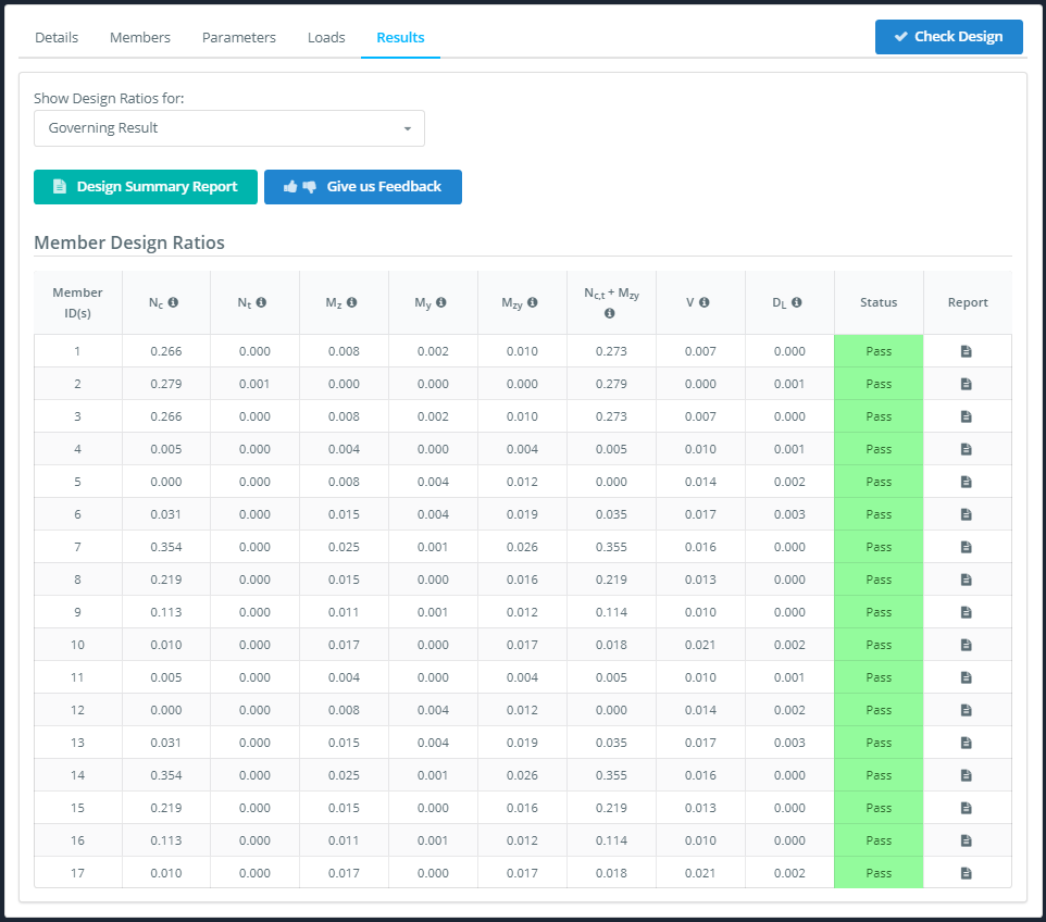
Resultados
Depois de concluir todas as etapas acima, você pode verificar seu design clicando no botão Verificar Design botão. O software irá alertá-lo se você tiver perdido algum campo obrigatório, caso contrário, você será levado para a guia Resultados.
No Resultados guia você tem uma visão geral das taxas de utilidade das verificações importantes no código de projeto na Proporções de Design de Membros tabela, se quiser mais detalhes, você pode clicar no Resumo do projeto botão para um relatório resumido.
Neste módulo de design de membro, relatórios individuais também estão disponíveis clicando no ícone do relatório na Relatório coluna do Proporções de Design de Membros tabela.
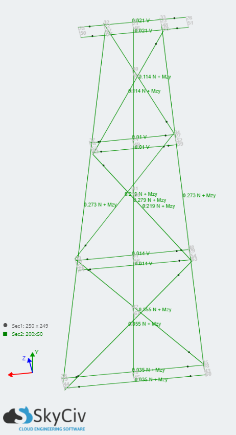
Finalmente, você pode ver os resultados gerais de governança de cada membro verificando os resultados exibidos no Modelo de estrutura de arame à esquerda.