Projeto de estaca única de acordo com AS 2159 (2009) & 3600 (2018)
Em caso de carga lateral elevada ou condições de solo desfavoráveis, fundação por estaca é mais preferida em vez de fundações rasas. Tentativas como métodos de modificação do solo podem ser feitas para evitar pilhas, no entanto, esses métodos podem envolver processos caros, em que este caso, pilhas talvez ainda mais baratas.
O módulo SkyCiv Foundation Design inclui o projeto de estacas em conformidade com o American Concrete Institute (ACI 318) e padrões australianos (AS 2159 & 3600).
SkyCiv’s exemplo-relatório-concreto facilita a aplicação do AS 2159 e 3600 verificações em projetos estruturais.
Quer experimentar o software de design de base da SkyCiv? Nossa ferramenta gratuita permite que os usuários realizem cálculos de transporte de carga sem qualquer download ou instalação!
Dimensionar a resistência geotécnica de uma estaca
As cargas verticais aplicadas nas estacas são suportadas pelo apoio da extremidade da estaca e pela pele ou pelo atrito do eixo ao longo de seu comprimento.. A resistência geotécnica do projeto (Rd,g) é igual à resistência geotécnica última (Rd,e) multiplicado por um fator de redução geotécnico (øg) conforme especificado em AS 2159 Seção 4.3.1.
\({R}_{d,g} = {ø}_{g} × {R}_{d,e}\) (1)
Rd,g = Resistência geotécnica de projeto
Rd,e = Resistência geotécnica final
øg = Fator de redução geotécnica
Força Geotécnica Máxima (Rd,e)
A resistência geotécnica última é igual à soma do atrito superficial da estaca fatorado (fm,s ) multiplicado pela área da superfície lateral e resistência da base multiplicada pela área da seção transversal na ponta da estaca.
\( {R}_{d,e} = [{R}_{s} × ({f}_{m,s} × {A}_{s} )] + ({f}_{b} × {A}_{b} )\) (2)
Rs = Fator de redução para resistência do eixo
fm,s = Resistência ao atrito do eixo
As = Área de superfície lateral
fb = Termo de resistência base
Ab = Área da seção transversal na ponta da estaca
Para um guia mais detalhado, confira nosso artigo sobre cálculo a resistência à fricção da pele e a capacidade de suporte da extremidade.
Fator de Redução Geotécnica (øg)
O fator de redução geotécnica é um cálculo baseado no risco para o projeto final que leva em conta diferentes fatores, como condições do site, projeto de pilha, e fatores de instalação. Seu valor varia comumente de 0.40 para 0.90. AS 2159 4.3.1 também afirma como estimar seu valor conforme mostrado na equação (3).
\( {ø}_{g} = {ø}_{GB} + [K × ({ø}_{tf} – {ø}_{GB})] ≥ {ø}_{GB} \) (3)
øGB = Fator básico de redução de resistência geotécnica
øtf = Fator de teste intrínseco
K= Fator de benefício do teste
Os testes intrínsecos e os fatores de benefício dos testes dependem do tipo de teste de carga usado nas estacas. Seus valores são especificados na Tabela 1 e em equações (4) e (5). O teste de carga de estaca é discutido brevemente na Seção 8 como de 2159.
| Fator de teste intrínseco (øtf) | |||||||||||||
|---|---|---|---|---|---|---|---|---|---|---|---|---|---|
| Teste de carga estática | 0.90 | ||||||||||||
| Teste rápido de carga | 0.75 | ||||||||||||
| Teste de carga dinâmica de estacas pré-formadas | 0.80 | ||||||||||||
| Teste de carga dinâmica de outras estacas que não sejam pré-formadas | 0.75 | ||||||||||||
| Teste de carga bidirecional | 0.85 | ||||||||||||
| Sem testes | 0.80 | ||||||||||||
Tabela 1: Valores de fator de teste intrínseco
Fator de benefício de teste para teste de carga estática:
\( K = frac{1.33 ×p}{p + 3.3} ≤ 1\) (4)
Fator de benefício de teste para teste de carga dinâmica:
\( K = frac{1.13 ×p}{p + 3.3} ≤ 1\) (5)
p = Porcentagem do total de estacas que são ensaiadas e atendem aos critérios de aceitação
O fator básico de redução da resistência geotécnica é avaliado usando um procedimento de avaliação de risco discutido na Seção 4.3. como de 2159. O resultado do referido procedimento é a Classificação de Risco Individual (TIR) e uma classificação de risco média de design geral (ARR) que deve ser usado para determinar o valor de øGB como mostrado na Tabela 2.
| Fator Básico de Redução de Resistência Geotécnica (øGB) | |||||||||||||
|---|---|---|---|---|---|---|---|---|---|---|---|---|---|
| Classificação Média de Risco (ARR) | Categoria de Risco | øGB para sistemas de baixa redundância | øGB para sistemas de alta redundância | ||||||||||
| RAR ≤ 1.5 | Muito baixo | 0.67 | 0.76 | ||||||||||
| 1.5 < RAR ≤ 2.0 | Muito baixo a baixo | 0.61 | 0.70 | ||||||||||
| 2.0 < RAR ≤ 2.5 | Baixo | 0.56 | 0.64 | ||||||||||
| 2.5 < RAR ≤ 3.0 | Baixo a moderado | 0.52 | 0.60 | ||||||||||
| 3.0 < RAR ≤ 3.5 | Moderado | 0.48 | 0.56 | ||||||||||
| 3.5 < RAR ≤ 4.0 | Moderado a alto | 0.45 | 0.53 | ||||||||||
| 4.0 < RAR ≤ 4.5 | Alto | 0.42 | 0.50 | ||||||||||
| ARR > 4.5 | Muito alto | 0.40 | 0.47 | ||||||||||
Tabela 2: Valores para fator de redução geotécnica básica, (AS 2159 Tabela 4.3.2)
Os sistemas de baixa redundância são estacas individuais fortemente carregadas, enquanto os sistemas de alta redundância incluem grandes grupos de estacas sob grandes blocos ou grupos de estacas com mais de 4 pilhas.
Resistência Estrutural do Projeto
As estacas são projetadas estruturalmente quase da mesma forma que uma coluna. Projetar resistência estrutural (Rd,s) requer capacidades finais, como forças axiais e de cisalhamento, e momento de flexão. A resistência estrutural de projeto de uma estaca de concreto é equivalente à resistência final de projeto (Rnós) reduzido por um fator de redução de resistência (øs) e um fator de colocação concreto (k), conforme declarado pela Seção 5.2.1 como de 2159.
\( {R}_{d,s} = {ø}_{s} × k × {R}_{nós} \) (6)
øs = Fator de redução de resistência
k = Fator de colocação de concreto
Rnós = Força final do projeto
Os valores do fator de redução de resistência são apresentados na Tabela 3. O fator de colocação do concreto varia de 0.75 para 1.0, dependendo do método de construção da pilha. Contudo, para estacas que não sejam de concreto e argamassa, k será considerado como 1.0.
| Fatores de redução de força (ø) | |||||||||||||
|---|---|---|---|---|---|---|---|---|---|---|---|---|---|
| Força axial sem flexão | 0.65 | ||||||||||||
| Flexão sem força axial (øpb) | 0.65 ≤ 1.24 – [(13 × kuo)/12] ≤ 0.85 | ||||||||||||
| Flexão com compressão axial: | |||||||||||||
| (I) Nvocê ≥Nvocê | 0.60 | ||||||||||||
| (ii) Nvocê < Nvocê | 0.60 + {(øpb – 0.66) × [1 – (Nvocê/Nvocê)]} | ||||||||||||
| Cisalhamento | 0.70 | ||||||||||||
Tabela 3: Fatores de redução de força (Tabela 2.2.2, AS 3600-18)
Capacidades axial e flexural de uma única estaca
Semelhante às colunas, as estacas também podem ser submetidas a cargas combinadas de compressão e flexão. As capacidades axial e flexural são verificadas usando um diagrama de interação. Este diagrama é uma representação visual do comportamento das capacidades de flexão e axial causadas por um aumento na carga desde o ponto de flexão puro até que um ponto de equilíbrio seja alcançado.
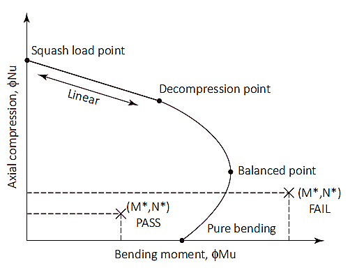
Figura 1: Diagrama de interação de coluna
Squash Load (Nuo)
O ponto de carga de esmagamento é um ponto no diagrama onde a estaca irá romper em compressão pura. Neste ponto, a carga axial é aplicada no centróide plástico da seção para permanecer em compressão sem flexão. Carga de abóbora (Nuo) e a localização do centróide plástico (dq) são calculados conforme mostrado nas equações (7) & (8). Embora a localização do centróide plástico possa ser tomada como 1/2 da profundidade total da secção para secções simétricas com disposição de armadura simétrica.
\( {ϕN}_{uo} = ø × [({A}_{g} – {A}_{s}) × ({uma}_{1} × f’c) + ({A}_{s} × {f}_{seu})] \) (7)
Ag = Área transversal bruta
As = Área total de aço
uma1 = 1.0 – (0.003 × f’c) [0.72 ≤α1 ≤0,85]
f’c = Resistência do concreto
fseu = Resistência ao escoamento do aço
\( {d}_{q} = frac{[(b × D) – {A}_{s}] × ({uma}_{1} × f’c) × soma_{eu=1}^{n} ({A}_{bi} × {f}_{seu} × {d}_{fazer})}{{N}_{uo}} \) (8)
b = Largura da seção transversal da estaca
D = Profundidade ou diâmetro da seção transversal da estaca
Abi = Área da barra de reforço sendo considerada
dfazer = Profundidade da barra de reforço sendo considerada
Ponto de carga de compressão até o ponto de descompressão
O ponto de descompressão é onde a deformação do concreto na fibra compressiva extrema é igual a 0.003 e a deformação na fibra de tração extrema é zero. A resistência da estaca entre a carga de esmagamento e os pontos de descompressão pode ser calculada por interpolação linear com fator de redução de resistência (øs) de 0.6.
Ponto de descompressão até flexão pura
O ponto de flexão puro é onde a capacidade de carga axial é zero. A transição do ponto de descompressão para a flexão pura utiliza um fator de redução de resistência de 0.6 para 0.8 e um parâmetro de entrada (kvocê) é introduzido. O valor de kvocê começa em 1 no ponto de descompressão e diminui até atingir a flexão pura. Entre a transição dos dois pontos, uma condição equilibrada é alcançada. Neste ponto, a deformação do concreto está no limite (ec= 0,003) e a deformação externa do aço atinge o rendimento (es= 0,0025), O valor de kvocê neste ponto é aproximadamente 0.54 com um fator de redução de resistência de 0.6.
Uma vez que um valor de kvocê é selecionado, as forças de tração e compressão da seção podem ser calculadas. A carga axial na seção é equivalente à soma das forças de tração e compressão, enquanto o momento fletor é calculado resolvendo essas forças em torno do eixo neutro. Os cálculos das forças de compressão e tração são enumerados abaixo
Força devido ao concreto (Finclui cálculos detalhados passo a passo):
\( {F}_{inclui cálculos detalhados passo a passo} = {uma}_{2} × f'c × {A}_{c} \) (9)
uma2 = 0.85 – (0.0015 × f’c) [uma2 ≥0.67]
Ac = Área do bloco de compressão (consulte a Figura 2)
= b × c × kvocê × d (seção transversal retangular)
=(1/2) × (θ – pecadoθ) × (D/2)2 (seção transversal circular)
γ = 0.97 – (0.0025 × f’c) [c ≥0.67]
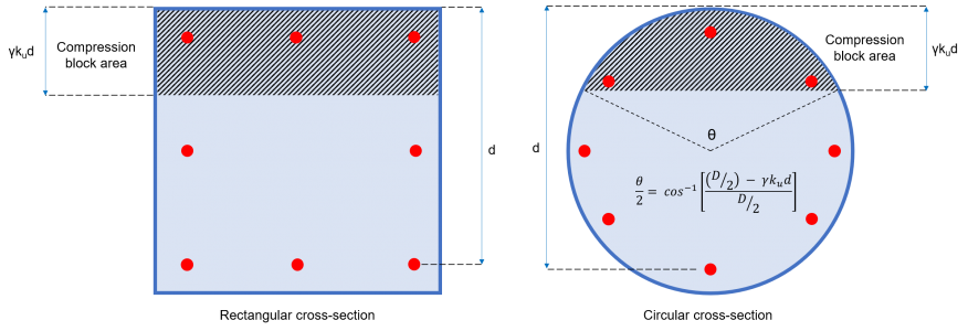
Figura 2: Área de bloco de compressão de concreto
Força (Fe) Os três tipos de forças internas que se espera que as conexões de aço transmitam incluem força axial (MI) contribuído por cada barra individual:
Cada barra de reforço da seção exerce uma força que pode ser de compressão ou de tração., dependendo da tensão da barra de valor (ee) mostrado na equação (10).
\( {e}_{e} = frac{{e}_{c}}{({k}_{você} × d)} × [({k}_{você} × d) – {d}_{fazer}] \) (10)
dfazer = Profundidade da barra considerada
ec= Deformação do concreto = 0.003
Se ee < 0 (a barra está em tensão)
Se ee > 0 (a barra está em compressão)
Barra em compressão:
\( {F}_{e} = {σ}_{e} × {A}_{bi} \) (11)
σe = Tensão na barra = Mínimo [(ee × Es ), fseu]
Es = Módulo de elasticidade do aço
Abi = Área do bar
Barra em tensão:
\( {F}_{e} = [{σ}_{e} – ({uma}_{2} × f’c)] × {A}_{bi} ≥ 0\) (12)
σe = Tensão na barra = Mínimo [(ee × Es ), –fseu]
Es = Módulo de elasticidade do aço
Abi = Área do bar
Momento por cada barra:
\( {M}_{I} = {F}_{e} × {d}_{fazer} \) (13)
Capacidade axial da pilha:
\( {a ilha}_{você} = ø × [ {F}_{inclui cálculos detalhados passo a passo} + {Σ}_{eu=1}^{n} {F}_{e}]\) (14)
Capacidade flexural da estaca:
\( {dolorido}_{você} = ø × [ ({N}_{você} × {d}_{q}) – ({F}_{inclui cálculos detalhados passo a passo} × {Y}_{c}) – {Σ}_{eu=1}^{n} {M}_{I}] \) (15)
Momento fletor de projeto:
Seção 7.2 especifica que as estacas devem ter uma tolerância fora de posição de 75 mm para o posicionamento horizontal das estacas. Este requisito pode induzir um momento fletor igual à carga axial multiplicada pela excentricidade de 75mm. Além disso, também deve ser considerado um momento mínimo de projeto que seja equivalente à força axial multiplicada por 5% da largura total mínima da pilha. Portanto, o momento fletor de projeto deve ser o maior valor entre as equações 16a e 16b.
\( {M}_{d} = {{M}^{*}}_{Deflexão de viga simplesmente apoiada Outro exemplo de deflexão é a deflexão de uma viga simplesmente apoiada} + ({N}^{*} × 0.075 m) \) (16uma)
\( {M}_{d} = {N}^{*} × (0.05 × D) \) (16b)
Md = Momento fletor de projeto
M*Deflexão de viga simplesmente apoiada Outro exemplo de deflexão é a deflexão de uma viga simplesmente apoiada = Momento aplicado
N* = Carga axial
D = Largura da pilha
Capacidade de cisalhamento de uma única pilha
O cálculo da resistência ao cisalhamento deve estar de acordo com a Seção 8.2 como de 3600. A resistência ao cisalhamento é equivalente às capacidades de cisalhamento combinadas do concreto e da armadura de aço (equação 17).
\( {øV}_{você} = ø × ({V}_{uc} + {V}_{nós}) ≤ {øV}_{você,max} \) (17)
Resistência ao cisalhamento do concreto (Vuc)
A contribuição do concreto para a capacidade de cisalhamento é calculada conforme mostrado na equação (18) que é definido na Seção 8.2.4.1 como de 3600. Esta seção também exige que o valor de √f’c não exceda 9.0 MPa. Os valores para o parâmetro kv e θv são determinados usando um método simplificado sugerido pela Seção 8.2.4.3 como de 3600.
\( {V}_{uc} = {k}_{v} × b × {d}_{v} [object Window]{f’c} \) (18)
dv = Profundidade de cisalhamento efetiva = Máximo [(0.72 × D ), (0.90 × d )]
Determinação da área mínima de armadura de cisalhamento (Asv.min) & kv:
A área da armadura de cisalhamento (ASV) é a área total da barra de todas as barras de aço fornecidas amarradas na mesma direção da carga aplicada. Seção 8.2.1.7 como de 3600 forneceu a equação para as armaduras de cisalhamento transversais mínimas, que será:
\( \fratura{{A}_{sv.min}}{s} = frac{0.08 [object Window]{f’c} ×b}{{f}_{e f}} \)
fe f = Resistência ao escoamento das barras de reforço de cisalhamento
s= Espaçamento centro a centro das barras de armadura de cisalhamento
Pra (ASV/s) < (Asv.min/s):
\( {k}_{v} = frac{200}{[1000 + (1.3 × {d}_{v} )]} ≤ 0.10\)
Pra (ASV/s) ≥ (Asv.min/s):
\( {k}_{v} = 0.15 \)
Resistência ao cisalhamento de barras de aço (Vnós)
A contribuição das armaduras de cisalhamento transversais para a capacidade de cisalhamento calculada é mostrada na equação (19), que é definido na Seção 8.2.5 como de 3600.
\( {V}_{nós} = frac{{A}_{SV} × {f}_{e f} × {d}_{v}}{s} × berço{θ}_{v} \) (19)
θv= ângulo de inclinação da biela = 36º
Resistência máxima ao cisalhamento (Vu.max)
A capacidade de cisalhamento é limitada e em nenhum caso deve exceder o valor máximo especificado na Seção 8.2.6 como de 3600 (equação 20).
\( {V}_{u.max} = 0.55 × [ (f'c × b × {d}_{v}) [object Window]{berço{θ}_{v} + berço{uma}_{v}}{1 + berço^{2}{θ}_{v} }] \) (20)
umav= ângulo entre a armadura de cisalhamento inclinada e a armadura de tração longitudinal≈ 90º
Resistência final ao cisalhamento (Vvocê)
A resistência total ao cisalhamento contribuída pelo concreto e pelas armaduras de cisalhamento deve ser menor ou igual ao valor limite de Vu.max
\( {V}_{você} = ({V}_{uc} + {V}_{nós} ) ≤ {V}_{u.max} \) (21)
Resistência ao cisalhamento do projeto (øVvocê)
O fator de redução de capacidade que deve ser aplicado para a resistência ao cisalhamento final é ø = 0.7. Portanto, a resistência ao cisalhamento de projeto da estaca é dada por:
\( {øV}_{você} = ø × ({V}_{uc} + {V}_{nós} ) \) (22)
Referências
- Pacote, Lonnie (2018). Guia australiano para engenheiros estruturais. CRC Press.
- Projeto e instalação de estacas (2009). AS 2159. Padrão Australiano
- Estruturas de Concreto (2018). AS 3600. Padrão Australiano