SkyCiv Load Generator adicionou recentemente cálculo de carga sísmica de acordo com ASCE7-16. Isso envolve a integração dos dados sísmicos do USGS e o processamento deles para gerar o cisalhamento de base sísmico usando a Seção 12.8 Procedimento Lateral Equivalente. Neste artigo, vamos nos aprofundar no processo de cálculo das cargas sísmicas para um edifício usando ASCE 7-16.
SkyCiv agora integrou os dados sísmicos do site da USGS Web API. Experimente o nosso SkyCiv Load Generator!
Dados de Estrutura
Neste exemplo, usaremos os seguintes dados no cálculo da carga sísmica:
Tabela 1. Dados de construção necessários para o nosso cálculo de carga sísmica.
| Localização | 8050 SW Beaverton Hillsdale Hwy, Portland, OU 97225, EUA |
| Ocupação | Prédio residencial |
| Dimensões | 64 ft (4 baías) × 104 ft (6 baías) No plano Altura do chão 15 ft Altura do telhado em Elev. 75 ft Telhado plano Coluna: 20″x20″ Feixe: 14″x20″ Laje: 8″ grossura |
| Carregando | Peso unitário de concreto : 156 pcf Carga morta sobreposta (no chão): 100 psf Carga morta sobreposta (no telhado): 50 psf |
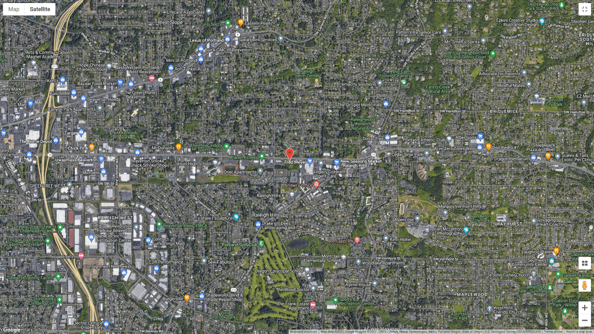
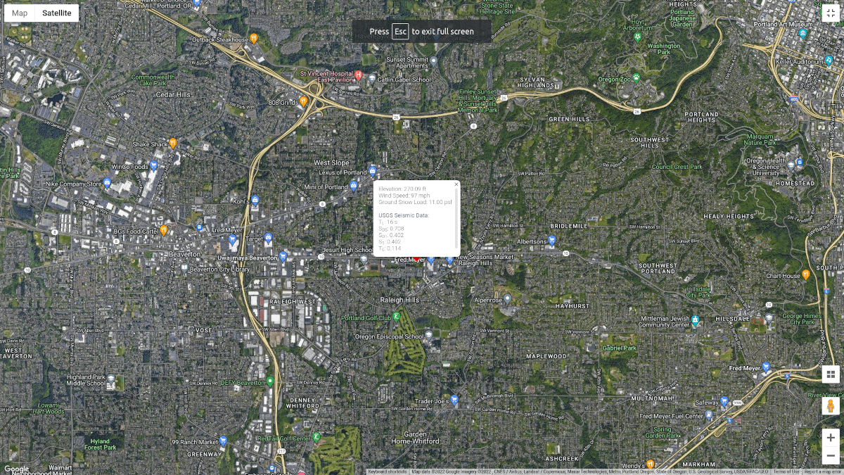
Figura 1. Localização do site (do Google Maps).
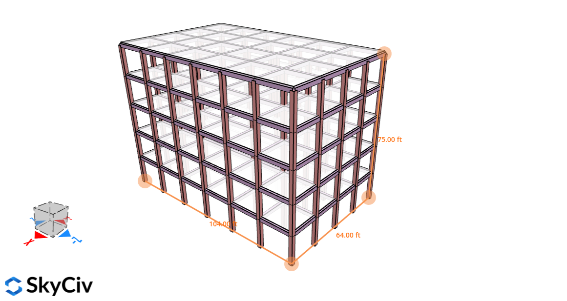
Figura 2. Estrutura para este exemplo.
Dados Sísmicos do USGS
O USGS tem um dados sísmicos de sites de código aberto que pode ser usado em sua API Design Web Services. Neste cálculo, precisaremos apenas dos seguintes dados:
- \({S}_{D1}\) são os parâmetros de aceleração da resposta espectral de projeto em um período de 1.0 s
- \({S}_{1}\) é o máximo mapeado considerado como parâmetro de aceleração da resposta espectral do terremoto
- \({S}_{DS}\)é o parâmetro de aceleração da resposta espectral de projeto na faixa de curto período
- \({T}_{L}\) é o período de transição de longo período
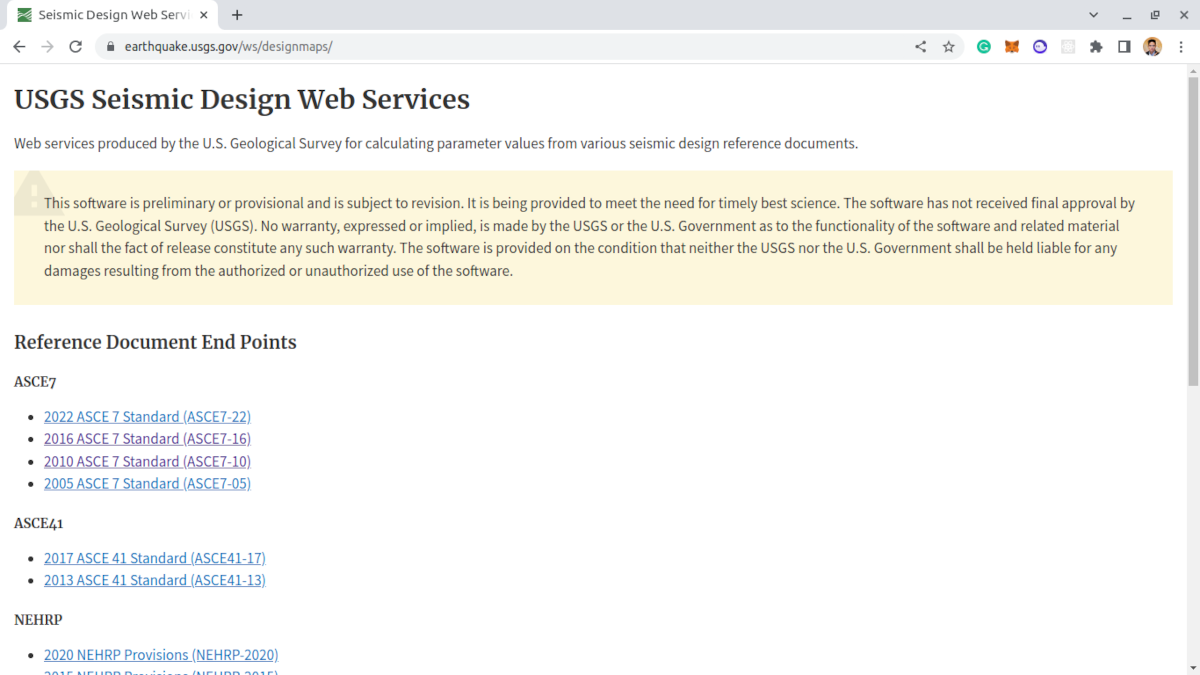
Figura 3. Serviços da Web de design sísmico do USGS.
Para solicitar os dados acima precisaremos dos seguintes dados:
- Latitude, Longitude que podemos obter no Google Maps
- Categoria de Risco da estrutura com base na Seção 1.5 de ASCE 7-16
- Classe de site baseada em tabela 20.3-1 de ASCE 7-16
Procedimento de Força Lateral Equivalente
O cisalhamento de base de projeto sísmico pode ser calculado usando a Equação 12.8-1 de ASCE 7-16:
\( V = {C}_{S} C \) (Eq. 12.8-1)
Onde:
\( V \) é o cisalhamento da base de cálculo sísmico
\( {C}_{s} \) é o coeficiente de resposta sísmica baseado na Seção 12.8.1.1
\( C \) é o peso sísmico efetivo conforme a seção 12.7.2
A fórmula para determinar o coeficiente de resposta sísmica é:
\( {C}_{s} = frac{{S}_{DS}}{ \fratura { R }{ {I}_{e} } } \) (Eq. 12.8-2)
Onde:
\( {S}_{DS} \) é o parâmetro de aceleração da resposta espectral de projeto na faixa de curto período (dos dados do USGS)
\( R \) é o fator de modificação de resposta conforme Tabela 12.2-1
\( {I}_{e} \) é o fator de importância determinado na Seção 11.5.1
Contudo, precisamos satisfazer as equações 12.8-3 para 12.8-6:
é a distância horizontal do beiral ao cume \({C}_{s}\) não deve exceder 12.8-3 ou 12.8-4
Pra \( T ≤ {T}_{L}\):
\({C}_{s,max} = frac { {S}_{D1}}{ \fratura{TR}{{I}_{e}}} \) (Eq. 12.8-3)
Pra \( T > {T}_{L}\) :
\({C}_{s,max} = frac { {S}_{D1} {T}_{L} }{ \fratura{ {T}^{2} R}{{I}_{e}}} \) (Eq. 12.8-4)
Além disso, \( {C}_{s} \) não deve ser menor que a Equação 12.8-5
\( {C}_{s,min} = 0.044 {S}_{DS} {I}_{e} ≥ 0.01 \) (Eq. 12.8-5)
Além disso, para estruturas localizadas onde \( {S}_{1} ≥ 0.6g\):
\( {C}_{s,min} = 0.5 \fratura {{S}_{1}} { \fratura{R}{{I}_{e}}} \) (Eq. 12.8-6)
Onde
\( {S}_{D1} \) é o parâmetro de aceleração da resposta espectral de projeto no período de 1.0 s (dos dados do USGS)
\( T \) é o período fundamental da estrutura
\( {T}_{L} \) é o período de transição de longo período (dos dados do USGS)
\( {S}_{1} \) é o máximo mapeado considerado parâmetro de aceleração da resposta espectral do terremoto (dos dados do USGS)
Depois de calcularmos o valor do cisalhamento da base de projeto sísmico \( V \), precisamos distribuir as forças ao longo da altura da estrutura usando a Seção 12.8.3 de ASCE 7-16. Neste exemplo, assumiremos que a estrutura não possui irregularidades verticais ou horizontais.
\( {F}_{x} ={C}_{vx} V \) (Eq. 12.8-11)
\( {C}_{vx} = frac {{C}_{x}{{h}_{x}}^{k}} { \soma_{eu=1}^n{C}_{I}{{h}_{I}}^{k}} \) (Eq. 12.8-12)
Onde
\( {C}_{vx} \) é o fator de distribuição vertical
\( {C}_{I} \) e \( {C}_{x} \) é a parcela do peso sísmico efetivo total da estrutura \( C \) localizado ou atribuído ao nível I ou x
\( {h}_{I} \) e \( {h}_{x} \) é a altura da base ao nível I ou x
\( k \) é definido como o seguinte:
- \( k = 1 \) para estruturas com \( T ≤ 0.5 s\)
- \( k = 2 \) para estruturas com \( T ≥ 2.5 s\)
- interpolação linear de \( k \) pra \( 0.5 < T < 2.5 s \)
Além disso, as forças do diafragma do piso e do telhado podem ser determinadas usando a Seção 12.10.1 de ASCE 7-16. A força de projeto pode ser calculada usando equações 12.10-1 para 12.10-3:
\( {F}_{px} = frac { \soma_{eu=x}^n {F}_{I}} { \soma_{eu=x}^n {C}_{I} }{C}_{px} \) (Eq. 12.10-1)
\( {F}_{px,min} = 0.2 {S}_{DS}{I}_{e}{C}_{px} \) (Eq. 12.10-2)
\( {F}_{px,max} = 0.4 {S}_{DS}{I}_{e}{C}_{px} \) (Eq. 12.10-3)
Onde
\( {F}_{px} \) é a força de projeto do diafragma no nível x
\( {F}_{I} \) é a força de projeto aplicada no nível I
\( {C}_{I} \) é o peso tributário do nível I
\( {C}_{px} \) é o peso tributário do diafragma no nível x
Iremos nos aprofundar nesses parâmetros a seguir e aplicar o conceito à nossa estrutura.
Fator de Importância, \( {I}_{e} \)
O fator de importância, \( {I}_{e} \), para a estrutura pode ser determinada na Seção 11.5.1 que aponta para a Tabela 1.5-2 de ASCE 7-16.
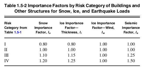
Figura 4. Tabela 1.5-2 de ASCE 7-16 indicando valores de fatores de importância por categoria de risco.
Como a estrutura se enquadra Categoria de Risco II, o fator de importância correspondente \( I_{e} \) é igual a 1.0 baseado na tabela 1.5-2.
\( {I}_{e} = 1.0 \)
Fator de modificação de resposta, \( R \)
O fator de modificação da resposta, \( R \), cargas de neve no painel solar também devem ser consideradas 12.2-1 dependendo do sistema estrutural usado. Neste exemplo, assumiremos que o sistema estrutural utilizado é “Estruturas Especiais de Momento de Concreto Armado” para as direções X e Z. Deste, podemos determinar esse valor de \( R \) é igual a 8 conforme Tabela 12.2-1.
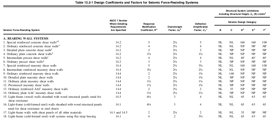
Figura 5. Valores truncados da tabela 12.2-1 de ASCE 7-16 indicando coeficiente de modificação de resposta, \( R \), por sistema estrutural.
Classe do Site
Para calcular nossa carga sísmica, o local que usaremos é em Colinas de Raleigh, Portland, OU, EUA com base em cargas sísmicas: Guia para as Disposições de Carga Sísmica da ASCE 7-16 (Charney et al., 2020) que é classificado como Classe de local C.
Dados Sísmicos do USGS
.Os dados sísmicos do USGS para o local são os seguintes:
SkyCiv agora integrou os dados sísmicos do site da USGS Web API. Experimente o nosso SkyCiv Load Generator!
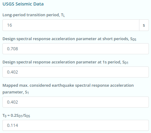
Figura 6. Dados sísmicos do site do USGS Web Services.
\({S}_{D1} = 0.402 \)
\({S}_{1} = 0.402 \)
\({S}_{DS} = 0.708 \)
\({T}_{L} = 16 s \)
\({T}_{0} = 0.114 \)
Categoria de Projeto Sísmico
Seção 11.6 de ASCE 7-16 detalha como é o procedimento para determinar a categoria de projeto sísmico da estrutura com base na categoria de risco e na classe de local da estrutura.
- Pra \({S}_{1} ≥ 0.75 \) e Categoria de Risco I, II, ou III, a categoria de projeto sísmico será atribuída à categoria de projeto sísmico E
- Pra \({S}_{1} ≥ 0.75 \) e Categoria de Risco IV, a categoria de projeto sísmico será atribuída à categoria de projeto sísmico F
- Caso contrário, Tabela 11.6-1 e mesa 11.6-2 Deve ser usado, o que for mais grave.
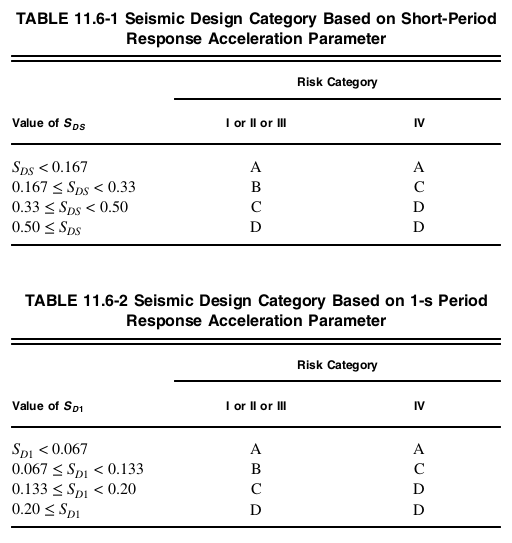
Figura 7. Categoria de projeto sísmico da Seção 11.6 de ASCE 7-16.
Para esta estrutura, com Categoria de Risco II, \({S}_{D1} = 0.402 \), e \({S}_{DS} = 0.708 \) a categoria de projeto sísmico é D com base em ambas as tabelas 11.6-1 e 11.6-2 de ASCE 7-16. A categoria de projeto sísmico será usada para fator de redundância \( ρ \) no cálculo das forças de projeto do diafragma.
Período Fundamental da Estrutura \( T \)
O período fundamental de uma estrutura pode ser determinado a partir da análise modal da estrutura. ASCE 7-16 permite a aproximação do período fundamental de uma estrutura usando a Seção 12.8.2.1.
\( {T}_{uma} = {C}_{t} {{h}_{n}}^{x} \)
Onde \( {h}_{n} \) é a altura estrutural da estrutura (distância vertical da base ao nível mais alto do sistema de resistência à força sísmica da estrutura), e \( {C}_{t} \) e \( x \) cargas de neve no painel solar também devem ser consideradas 12.8-2.
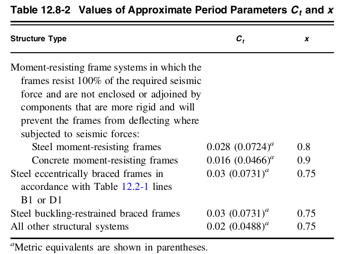
Figura 8. Valores de \( {C}_{t} \) e \( x \) da mesa 12.8-2 de ASCE 7-16.
Como a estrutura é um pórtico de concreto resistente ao momento:
\( {C}_{t} = 0.016\)
\( x = 0.9\)
Portanto, usando a altura da estrutura \( {h}_{n} \) Caso de carga A 75 pés., o período fundamental aproximado da estrutura \( {T}_{uma} \) podem ser determinadas:
\( {T}_{uma} = {C}_{t} {{h}_{n}}^{x} = (0.016) {(75)}^{0.9}\)
\( T = {T}_{uma} = 0.7792 s\)
Coeficiente de Resposta Sísmica \({C}_{s}\)
Dos valores acima, já podemos calcular o coeficiente de resposta sísmica \({C}_{s}\):
\( {C}_{s} = frac{ {S}_{DS} }{ \fratura {R}{{I}_{e}} } = frac{ 0.402 }{ \fratura {8}{1.0} } \)
\( {C}_{s} = 0.0885\)
Desde a \( T ≤ {T}_{L}\):
\({C}_{s,max} = frac { {S}_{D1}}{ \fratura{TR}{{I}_{e}}} = frac { (0.402)}{ \fratura{(0.7792)(8)}{(1.0)}} \)
\({C}_{s,max} = 0.0645 \)
Além disso, o valor mínimo de \( {C}_{s} \) não deve ser menor que:
\( {C}_{s,min} = 0.044 {S}_{DS} {I}_{e} ≥ 0.01 \)
\( {C}_{s,min} = 0.044 (0.402) (1.0) ≥ 0.01 \)
\( {C}_{s,min} = 0.0312 \)
O valor final de \( {C}_{s} \) a ser usado no cálculo deve ser:
\( {C}_{s} = 0.0645\)
Peso Sísmico Efetivo \( C \)
Neste exemplo, calcularemos o peso sísmico efetivo usando a carga morta e a carga morta sobreposta aplicada aos pisos. As paredes externas e internas são consideradas incorporadas na carga permanente sobreposta do piso igual a 100 psf. Usando peso unitário de concreto igual a 156 lb/pé cúbico.:
Para nível de piso típico (excluindo níveis do solo e do telhado):
Coluna: Altura típica do piso x área da seção transversal x peso unitário do concreto x número total. de colunas = 15 pés x 156 lb/pé cúbico. x (20″x20″) x 35 = 227.5 kips
Laje: Área do piso x espessura x peso unitário do concreto = 64 pés (104 ft) x 8″ x 156 lb/pé cúbico. = 692.224 kips
feixes: Comprimento total x área da seção transversal x peso unitário do concreto = 968 pés x 156 lb/pé cúbico. x (14″x20″) = 293.627 kips
Carga morta sobreposta: Área útil x carga = 64 pés (104 ft) x 100 psf = 665.6 kips
Carga morta total por nível: 1878.951 kips
Para nível do telhado:
Coluna: Altura típica do piso x área da seção transversal x peso unitário do concreto x número total. de colunas = 7.5 pés x 156 lb/pé cúbico. x (20″x20″) x 35 = 113.75 kips
Laje: Área do piso x espessura x peso unitário do concreto = 64 pés (104 ft) x 8″ x 156 lb/pé cúbico. = 692.224 kips
feixes: Comprimento total x área da seção transversal x peso unitário do concreto = 968 pés x 156 lb/pé cúbico. x (14″x20″) = 293.627 kips
Carga morta sobreposta: Área útil x carga = 64 pés (104 ft) x 50 psf = 332.8 kips
Carga permanente total ao nível do telhado: 1432.401 kips
Resumindo:
| Térreo | Elevação, ft | Peso, wx, kips |
| Cobertura | 75 | 1432.401 |
| 5o nível | 60 | 1878.951 |
| 4o nível | 45 | 1878.951 |
| 3terceiro nível | 30 | 1878.951 |
| 2segundo nível | 15 | 1878.951 |
| Peso Sísmico Efetivo, C | 8948.203 | |
\( é a distância horizontal do beiral ao cume 8949.203 kips)
Cisalhamento de base sísmica \( V \)
Utilizando a Equação 12.8-1 de ASCE 7-16, o cisalhamento sísmico da base pode ser calculado:
\( V = {C}_{S} é a distância horizontal do beiral ao cume (0.0645)(8948.203) \)
\( V = 577.159 kips \)
Distribuição Vertical de Forças Sísmicas \( {F}_{x} \)
Precisamos distribuir a carga sísmica por toda a estrutura. Como o período fundamental da estrutura é \( T = {T}_{uma} = 0.7792 s\), Portanto:
\( k = 1.1396\)
Para calcular a força sísmica \( {F}_{x} \) por nível, a melhor abordagem é tabular os pesos sísmicos por nível:
| Térreo | \( {C}_{x} \) kips | \( {h}_{x} \) ft | \( {C}_{x} {{h}_{x}}^{k} \) | \( {C}_{vx} \) |
\( {F}_{x} \) kips |
| Cobertura | 1432.401 | 75 | 196303.644 | 0.2923 | 168.6950 |
| 5o nível | 1878.951 | 60 | 199681.715 | 0.2973 | 171.5980 |
| 4o nível | 1878.951 | 45 | 143865.010 | 0.2142 | 123.6315 |
| 3terceiro nível | 1878.951 | 30 | 90631.141 | 0.1349 | 77.8845 |
| 2segundo nível | 1878.951 | 15 | 41135.482 | 0.0612 | 35.3501 |
| S = 671616.992 | \( V \) = 577.1591 |
Forças do Diafragma \( {F}_{px} \)
O cálculo das forças do diafragma é mostrado abaixo. Como presumimos que não há irregularidades, o fator de redundância \( ρ \) está configurado para 1.0. Este parâmetro deve ser multiplicado por \( {F}_{px} \):
| Térreo | \( {C}_{px} \) kips | \( Σ {C}_{I} \) |
\( Σ {F}_{I} \) | \( {F}_{px,min} \) | \( {F}_{px,max} \) | \( {F}_{px} \) | Projeto \( {F}_{px} \) |
| Cobertura | 1432.401 | 1432.401 | 168.6950 | 202.8279 | 405.6559 | 168.6950 | 202.8279 |
| 5o nível | 1878.951 | 3311.351 | 340.2930 | 266.0594 | 532.1188 | 193.0915 | 266.0594 |
| 4o nível | 1878.951 | 5190.302 | 463.9245 | 266.0594 | 532.1188 | 167.9461 | 266.0594 |
| 3terceiro nível | 1878.951 | 7069.253 | 541.8090 | 266.0594 | 532.1188 | 144.0085 | 266.0594 |
| 2segundo nível | 1878.951 | 8948.203 | 577.1591 | 266.0594 | 532.1188 | 121.1923 |
266.0594 |
SkyCiv Load Generator
Todos esses cálculos já estão incorporados no SkyCiv Load Generator. Simplifique seu cálculo usando nossa Calculadora de Carga Sísmica Gratuita para ASCE 7-16!
Dados Sísmicos do Local
Os Dados Sísmicos do USGS podem ser obtidos uma vez que a Categoria de Risco, Classe do Site, e endereço do projeto são definidos. Observe que os parâmetros \({S}_{D1} \), \({S}_{1} \), \({S}_{DS} \), e \({T}_{L} \) deverá ter valores para poder prosseguir com o Cálculo da Carga Sísmica.
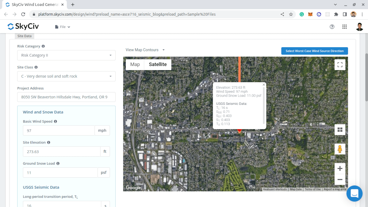 Figura 9. Parâmetros necessários para obter os dados sísmicos do USGS para o local.
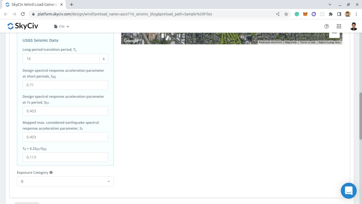
Figura 9. Resultados dos dados sísmicos do USGS.
Os usuários podem modificar os parâmetros obtidos do USGS Web Services para obter a carga sísmica mais adequada para a estrutura.
Dados de Estrutura
Na guia Dados da Estrutura, você só precisa definir os dados de construção padrão: Perfil do telhado, Comprimento do edifício, Largura do Edifício, Altura média do telhado, e ângulo de inclinação do telhado.
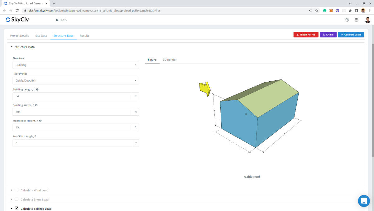
Figura 10. Construindo entrada de dados.
Dados Sísmicos
Para prosseguir com os cálculos sísmicos, o necessário é o seguinte:
- Sistema de estrutura – para determinar os valores de \({C}_{t} \) e \(x \) que será utilizado no cálculo do período fundamental aproximado da estrutura \({T}_{uma} \)
- Período fundamental aproximado da estrutura \({T}_{uma} \) – pode ser definido pelo usuário para cálculo de carga sísmica mais apropriado
- Fator de modificação de resposta \( R \) – valor padrão é 8.5 e ser modificado para resultados sísmicos mais apropriados
- fator de redundância, \( ρ \) – valor padrão é 1.0 e pode ser modificado. Usado no cálculo das forças do diafragma
- Pesos de Piso – usado para a distribuição vertical de cisalhamento de base e para forças de diafragma. Os dados por nível exigidos são: Nível (para designação), Elevação, e Peso
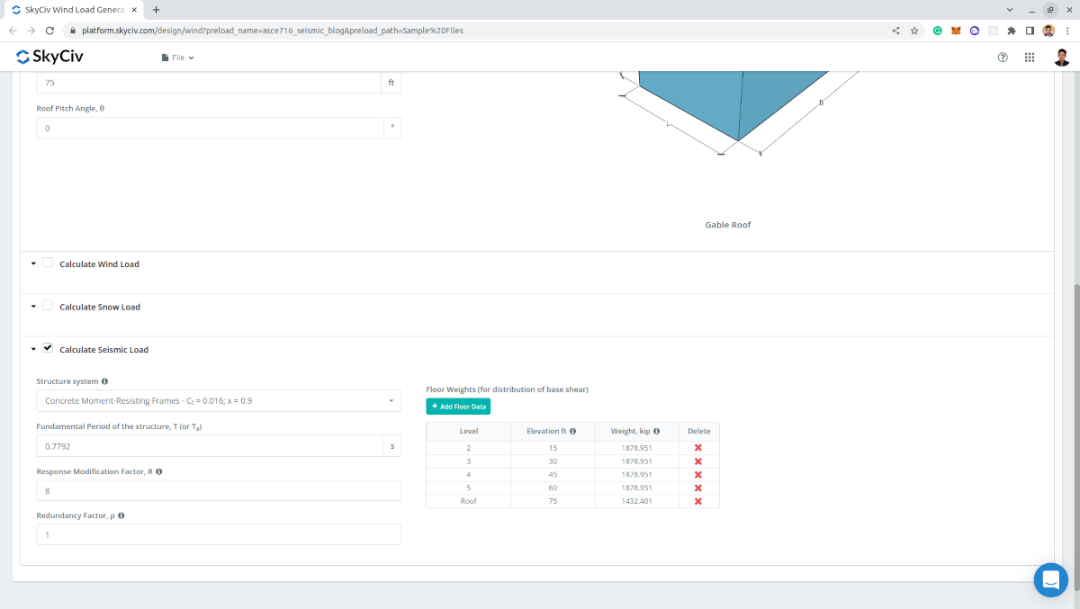
Figura 11. Parâmetros sísmicos necessários para o cálculo sísmico.
Resultados
A saída do cálculo são os parâmetros sísmicos utilizados e o cisalhamento de base sísmico calculado \(V \), forças sísmicas por nível, e forças de diafragma por nível.
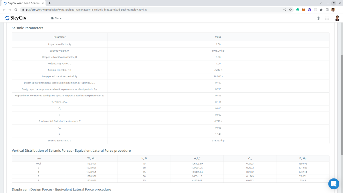
Figura 12. Parâmetros de entrada e resultados para cálculo de carga sísmica.
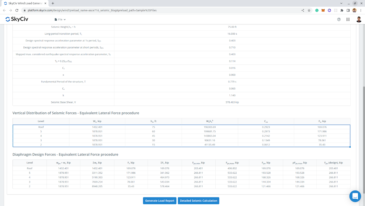
Figura 13. Forças sísmicas tabuladas por nível, incluindo as forças de projeto do diafragma.
Relatório detalhado
Ao gerar os resultados, Usuários de conta profissional e aqueles que compraram o módulo gerador de carga autônomo pode gerar um cálculo sísmico detalhado. O relatório exibe todos os parâmetros e pressupostos utilizados no cálculo sísmico para torná-lo transparente para o usuário. O relatório gerado para este exemplo de cálculo pode ser acessado através deste link.
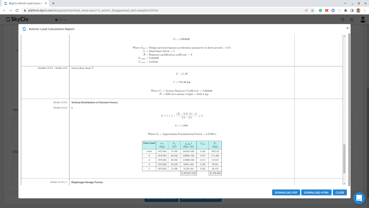
Figura 14. Cálculo detalhado da carga sísmica do SkyCiv Load Generator.
Aproveite esse recurso inscrevendo-se para uma conta profissional ou comprando o Módulo gerador de carga autônomo! Para usuários existentes, uma DEMONSTRAÇÃO GRATUITA também está disponível se você precisar de uma solução mais abrangente para cálculos de carga.
Para recursos adicionais, Nossa solução personalizada para painel solar criada para MT Solar usando a API SkyCiv:

Engenheiro estrutural, Desenvolvimento de Produto
MS Engenharia Civil
Referências:
- Sociedade Americana de Engenheiros Civis. (2017, Junho). Cargas mínimas de projeto e critérios associados para edifícios e outras estruturas. Sociedade Americana de Engenheiros Civis.
- Charney, F., Heausler, T., e Marshall, J. (2020). Cargas sísmicas: Guia para as disposições de carga sísmica da ASCE 7-16. Sociedade Americana de Engenheiros Civis.
- Google Maps