O que significam fixações de membros e como são identificadas no 3D estrutural
As fixações finais dos membros controlam como os membros são conectados entre si ou aos nós finais e incluem condições como um limite fixo, fixado, ou conexão de mola.
Os códigos de fixação final do membro aceitam ‘F’ (Fixo), 'R’ (Liberado) e 'S’ (Primavera) valores. Este código refere-se à conexão do membro final com seu nó final para cada um dos 6 graus de liberdade na seguinte ordem:
- Tradução local do eixo x
- Tradução local do eixo y
- Tradução local do eixo z
- Rotação local do eixo x
- Rotação local do eixo y
- Rotação local do eixo z
NOTA: As fixações finais do membro dizem respeito ao membro sistema de eixo local em vez do sistema de eixo global.
Fixo os membros têm um plano totalmente fixo, conexão rígida especificada por um código de fixidez ‘FFFFFF’.
Articulado os membros têm uma conexão articulada indicada por um código ‘FFFFRR’.
Primavera os membros têm uma conexão semirrígida permitindo flexibilidade parcial indicada por um código ‘FFFFSS’.
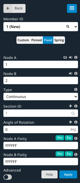
Para especificar valores personalizados, garantir que o Personalizado botão está selecionado. Isso permite que os campos de fixação final sejam editados.
Como informar o Member End Fixity enquanto olha no espaço do modelo
Ao modelar com membros, é conveniente conhecer os membros’ acabar com a fixidez sem ter que clicar em cada membro individualmente. Por padrão, quando os membros são modelados, eles têm fixações finais totalmente fixas (FFFFFF). O membro se parece com uma única linha entre nós:

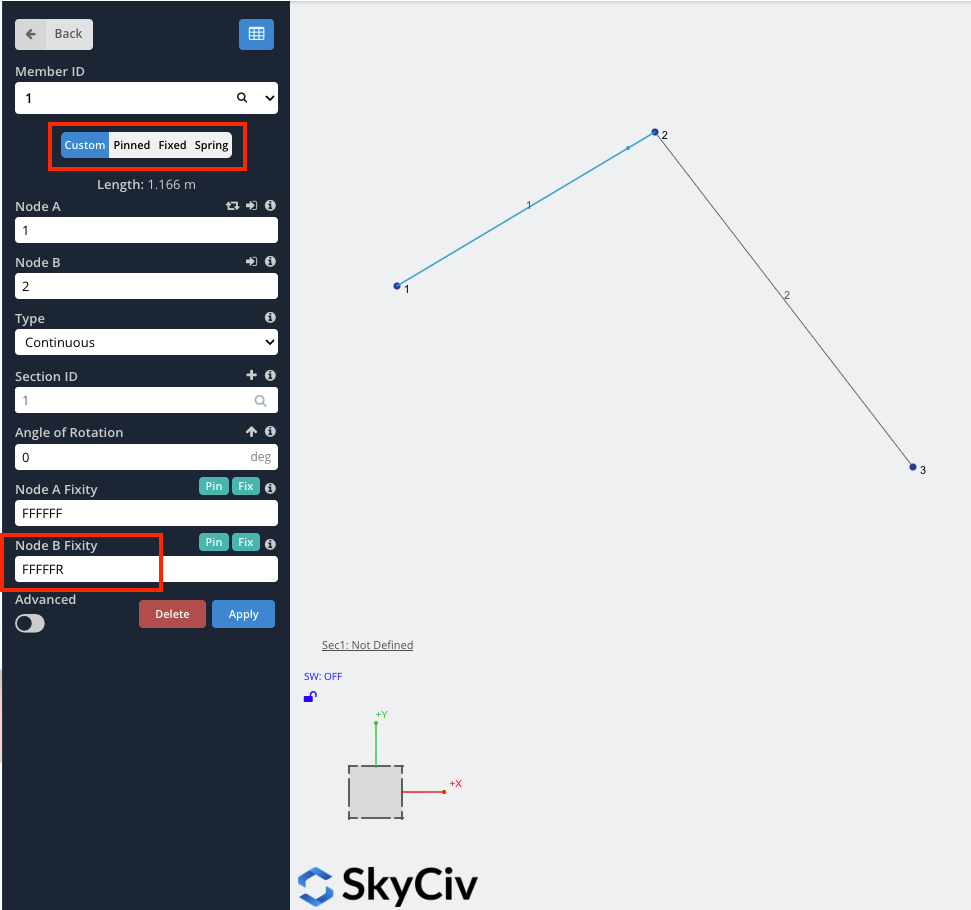
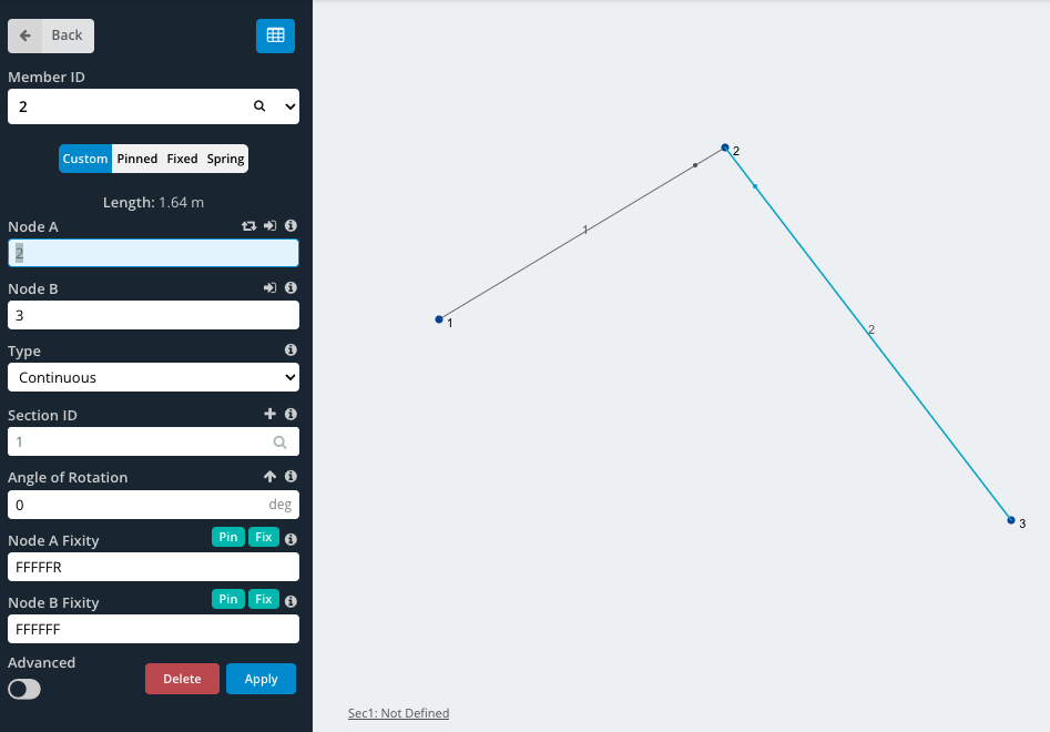
Quando qualquer um dos graus de liberdade é liberado, o membro terá um pequeno ponto próximo ao final do membro (conforme mostrado abaixo circulado em vermelho). Por exemplo, para membros com fixações finais fixadas (FFFRRR), o membro ficaria assim:

Explicação adicional
Para obter mais informações sobre fixações de membros, SkyCiv tem um artigo técnico (incluindo um vídeo) no nosso blog, focando em como modelar fixações de membros:
Exemplo: Como modelar conexões de pinos ou dobradiças
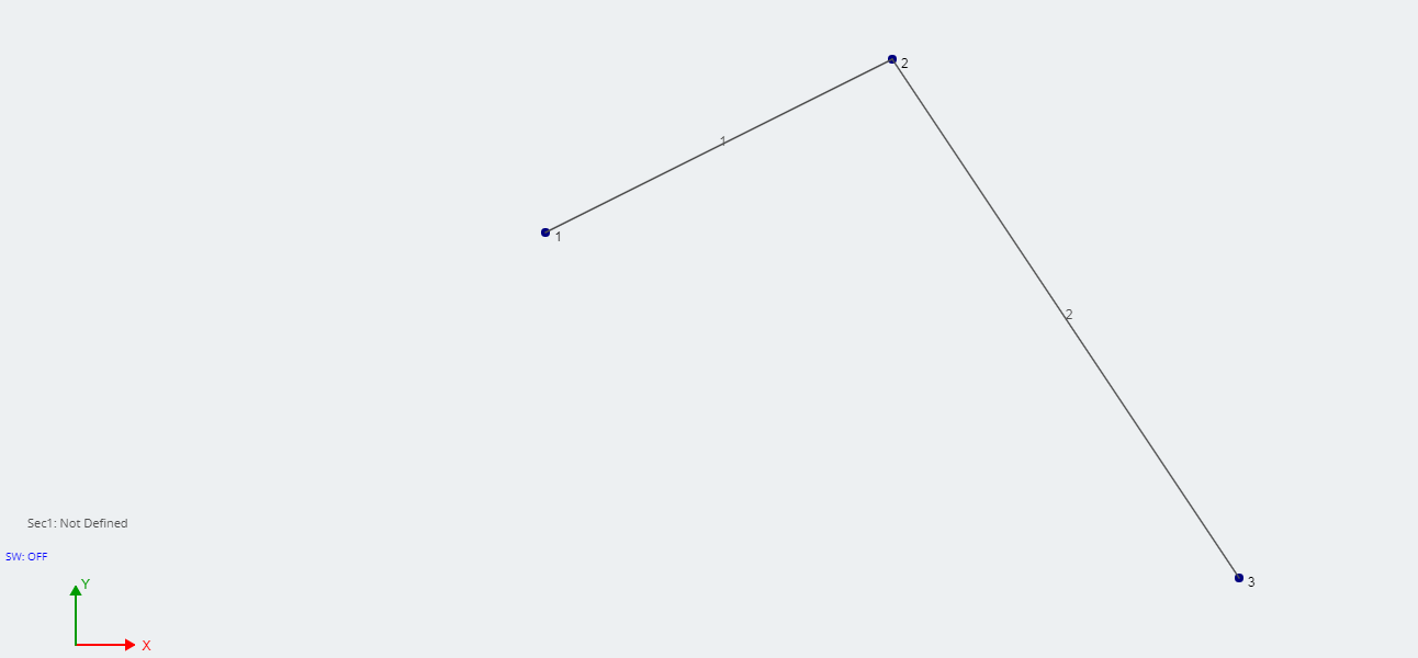
Neste exemplo, vamos criar uma conexão de pino simples, como uma dobradiça. Comece criando 3 nós e juntando-os com 2 membros. Neste nó de exemplo, 2 será a dobradiça.
Mais Informações
Para maiores informações, SkyCiv tem mais explicações sobre como modelar uma dobradiça, usando software de análise estrutural.