Um passo a passo e um exemplo de cálculo de cargas de desvio de neve e como aplicá-las
Projetos de telhado geralmente apresentam inúmeras elevações de telhado e raramente oferecem uma única altura de telhado. Por causa disso, existem áreas de telhado mais altas e mais baixas que as outras e estão sujeitas a montes de neve. A quantidade de carga de neve adicional, ou sobretaxa, pode e causará um grande impacto do design dos membros nessas áreas.
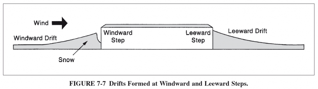
A geometria do telhado e a direção do vento são os dois motoristas que levam a desvios de neve. As duas direções do vento que causam os desvios de neve são “barlavento” e “sotavento”. Os desvios de neve em barlavento ocorrem quando o vento sopra a neve de um teto de elevação inferior em direção à parede de um adjacente, telhado mais alto. Os montes de neve de sotavento ocorrem quando o vento leva a neve de um telhado de maior elevação para um telhado adjacente inferior. Veja a figura 7-7 de ASCE 7-10 abaixo para uma representação sucinta:
Vamos supor que nosso projeto esteja em Madison, Wisconsin e já calculamos nosso equilíbrio, Carga de neve no telhado aqui. Do nosso exemplo, nossa carga no solo e carga de neve de teto plano foi considerado 30 psf e 21 psf, respectivamente. As disposições sobre como calcular a sobretaxa de desvio de neve para estruturas podem ser encontradas na seção 7.8 de ASCE 7-10.
O teto da nossa estrutura de exemplo tem duas alturas de telhado variadas e, portanto, precisamos calcular a sobretaxa de desvio da neve e aplicá -la aos nossos membros. No nosso caso, Nossas vigas são espaçadas em 10 pés.
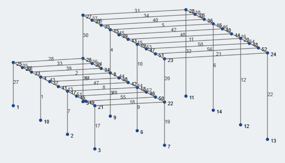
Figura 1: Visão isométrica de nossa estrutura de exemplo
Vamos primeiro reunir as informações geométricas relevantes sobre nossa estrutura. A baía inferior e o tamanho da baía superior são 25 pés e 37 pés, respectivamente. As elevações inferiores e mais altas do telhado são 15 pés e 30 pés da nota, respectivamente. A maioria dos valores geométricos pode ser associada a variáveis. Vamos dar uma olhada em todas as variáveis pertinentes para este cálculo.
\({p}_{g}\) cargas de neve no painel solar também devem ser consideradas
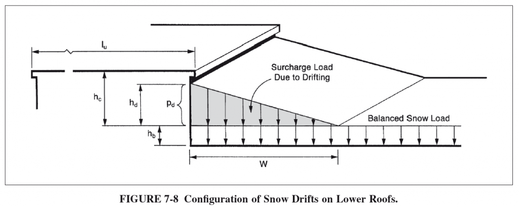
\({eu}_{você}\) = comprimento do telhado superior
\({eu}_{eu}\) = comprimento do telhado inferior
\({h}_{d}\) = altura do desvio da neve
\({C}\) = largura de desvio de neve
\({h}_{b}\) = altura da carga de neve equilibrada
\({h}_{c}\) = altura clara do topo da carga de neve equilibrada para o ponto mais próximo do telhado adjacente
\({h}_{r}\) = diferença de altura entre os telhados
\({p}_{s}\) = Projeto de carga de neve do capítulo 7
\({c}\) = densidade da neve
\({p}_{d}\) = carga de desvio de neve
Dê uma olhada na figura 7-8 de ASCE 7-10 Para uma representação de muitos desses termos e o que eles representam visualmente:
Encontrando a carga de sobretaxa de desvio de neve
Agora que identificamos quais são as variáveis, as configurações de carregamento de neve, e as restrições geométricas de nossa estrutura, Vamos calcular a deriva da neve.
Primeiro, Encontre se o carregamento da deriva da neve for necessário, como eixos 7.7-1:
A partir da elevação do solo gerada a partir das elevações do Google \({h}_{c}/{h}_{b} < 0.2\), Então a aplicação de desvio de neve não é necessária.
\({h}_{b} = {p}_{s}/{c}\), Onde:
\({c} = 0.13{p}_{g} + 14 ≤ 30 pcf\)
\({c} = 0.13*(30) + 14 = 17.9 PCF ≤ 30 pcf \)
\({h}_{b} = {21 psf}/{17.9 pcf} = 1.17 [object Window])
\({h}_{c} = {h}_{r}-{h}_{b}\)
\({h}_{c} = 15 ft – 1.17 ft = 13.8 [object Window])
\({h}_{c}/{h}_{b} = 13.8 ft/1,17ft = 11.8 > 0.2\) e portanto, O carregamento de desvio de neve é necessário.
Segundo, Encontre a altura máxima de desvio entre as direções de barlavento e sota:
A altura do desvio para as duas direções do vento pode ser encontrada usando a equação encontrada na figura 7-9 de ASCE 7-10, mostrado abaixo:
\({h}_{d} = 3/4*(0.43({eu}_{eu})^{1/3}({p_g}+10)^{1/4}-1.5)\) para deriva de barlavento
\({h}_{d} = 0.43({eu}_{você})^{1/3}({p_g}+10)^{1/4}-1.5\) Para deriva de Leeward
Altura de desvio de barlavento:
\({h}_{d} = 3/4*(0.43(25 ft)^{1/3}(30 psf+10)^{1/4}-1.5)\)
\({h}_{d} = 1.25 [object Window])
Altura de deriva de sotavento:
\({h}_{d} = 0.43(37 ft)^{1/3}(30 psf+10)^{1/4}-1.5\)
\({h}_{d} = 2.1 [object Window])
A altura máxima de desvio entre a altura do desvio de barlavento e sotaves será usada para o design, Portanto:
\({h}_{d} = 2.1 [object Window])
A continuação, Encontre a largura da sobretaxa de desvio de neve:
A largura da carga de desvio da neve, \({C}\), depende de \({h}_{c}\) e \({h}_{d}\)
Por seção 7.7.1,
A partir da elevação do solo gerada a partir das elevações do Google \({h}_{d} ≤ {h}_{c}\), então \({C} = 4{h}_{d}\)
A partir da elevação do solo gerada a partir das elevações do Google \({h}_{d} > {h}_{c}\), então \({C} = 4{h}_{d}^2/{h}_{c}) e subsequentemente \({h}_{d} = {h}_{c}\)
No nosso caso, \({h}_{c} = 13.8 [object Window]) e \({h}_{d} = 2.1 [object Window]), e portanto:
\({h}_{d} ≤ {h}_{c}\), e
\({C} = 4*(2.1 ft)\)
\({C} = 8.4 [object Window])
Observação, como eixos 7-10 a A largura de desvio da neve nunca deve exceder \(8{h}_{c}\)
Durar, Calcule a carga de sobretaxa de desvio da neve:
Para encontrar a carga máxima de sobretaxa, Multiplique a altura da deriva pela densidade da neve:
\({p}_{d} = {h}_{d}{c}\)
No nosso caso,
\({p}_{d} = (2.1 ft)*(17.9 pcf)\)
\({p}_{d} = 37.6 [object Window])
A carga máxima de sobretaxa de desvio de neve é sobreposta à carga de neve equilibrada:
\({p}_{max} = {p}_{d}+{p}_{s}\)
\({p}_{max} = 58.6 [object Window])
Aplicando as cargas de sobretaxa de desvio de neve
Vamos olhar para o quadro do meio da nossa estrutura. A área distribuída para as vigas neste avião é 10 ft por causa da constante 10 Espaçamento de feixe de ft. Figura 2 mostrado abaixo mostra a carga de neve equilibrada de 21 PSF aplicado ao teto de nossa estrutura. Observação, Todos os valores são infaturados, Cargas de serviço.
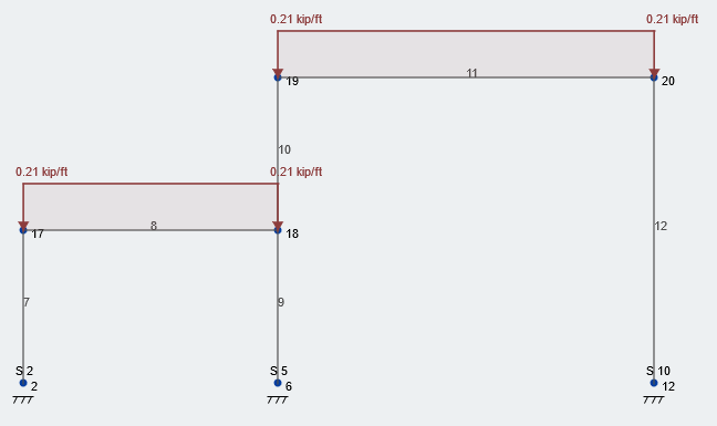
Figura 2: Condição de carregamento típica de carga de neve equilibrada
Agora, Vamos pegar a carga de sobretaxa de desvio da neve e a sobrepor em nossa estrutura. Figura 3 descreve a carga de desvio adicional no local correto. Como você pode ver, Nossa carga total de neve é 58.6 psf – arredondado para 59 psf – localizado na face da parede e depois diminui linearmente sobre o 8.4 largura de deriva de ft de volta à carga de neve balanceada constante. Esta condição de carregamento segue todo o comprimento da parede, em nosso curso, o comprimento da estrutura.
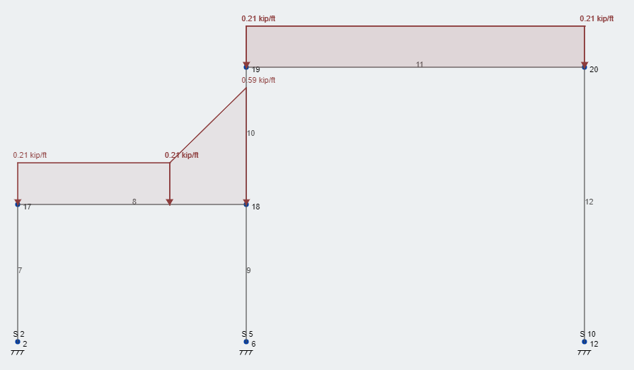
Figura 3: Cargas típicas de design de neve de nível de condição de carregamento
Neste ponto, as cargas de neve estão prontas para análise em conjunto com outros casos de carga e combinações de carga com base na ASCE 7-10 e outros códigos de construção pertinentes. Certifique -se de ler o capítulo 7 de ASCE 7-10 Para obter mais informações sobre provisões sucessivas para carga parcial de neve e carga de neve desequilibrada, Como essas condições não foram avaliadas aqui.
Referências:
- Cargas mínimas de projeto para edifícios e outras estruturas. (2013). EIXOS / SEIS 7-10. Sociedade Americana de Engenheiros Civis.