
As conexões de aço listadas neste artigo são projetadas de acordo com a Norma Australiana AS 4100:2020, Manual de Conexão do Australian Steel Institute 1, e guias de design do Australian Steel Institute 1-5.
Scope of the AS 4100 Módulo
Before going through the connection types, it is worth being clear about what the module covers under AS 4100.
AS 4100:2020 design in SkyCiv is for shear connections between I-sections, in metric units. Conexões de momento, splices and bracing connections are outside the current AS 4100 scope.
Viga Universal para Coluna Universal
Beam to column connections are among the most common connection types in steel design. The AS connections in SkyCiv are built around a supported beam framing into a supporting member, and the orientation can be set to a column flange support, a column web support, or a beam web support.
That third orientation means the same four connection types can also be used beam to beam, not only beam to column.
Only one connection to a node can be designed at a time. Ao lidar com conexões back-to-back, é aconselhável fazer suposições conservadoras no caminho de carga.
Conexões de cisalhamento
Uma conexão de cisalhamento é uma conexão simples. It is detailed to carry the beam end reaction and to rotate at the joint rather than to carry end moment, which is what separates it from a moment connection. In the AS module it is designed for shear alone, with no concurrent axial load.
Para o projeto AS, the following shear connection types are available:
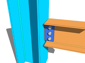
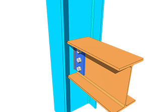
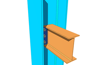
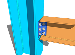
Each of the four is available beam to column flange, beam to column web, and beam to beam web.
-

- Placa Lateral Web – Viga para Flange da Coluna
-
- Placa Lateral Web – Transmitir para a Coluna Web
-
- Placa final flexível – Viga para Flange da Coluna

-
- Placa final flexível – Transmitir para a Coluna Web
-
- Ângulo Único – Viga para Flange da Coluna
-
- Ângulo Único – Transmitir para a Coluna Web
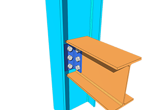
-
- Ângulo Duplo – Viga para Flange da Coluna
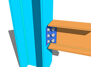
-
- Ângulo Duplo – Transmitir para a Coluna Web
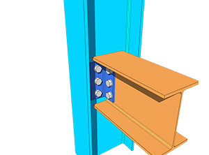
The design of the above shear connections was based mainly on ASI Design Guides 3, 4 e 5. The reference formulas were taken from the AS 4100:2020 manual, while the rest of the calculations and criteria were taken from the ASI Connection Handbook 1.
Coeficiente de Grupo de Parafusos
Para flexibilidade na disposição e espaçamento dos parafusos, SkyCiv adaptou o método ICOR e a análise inelástica na determinação do coeficiente C do grupo de parafusos, which is then used to calculate the bolt group shear capacity and bolt bearing capacity.
The Instantaneous Centre of Rotation Method (ICOR) usa iteração para localizar o IC do grupo de parafusos. SkyCiv usa seu próprio solucionador para essas iterações. A localização do IC está incluída nos cálculos, but the iterations are not shown, to keep the report concise and readable.
The equation used to calculate the force per bolt using the inelastic analysis is based on AISC Eq. (7-1) na página 7-7 do Manual AISC 15ª Edição. A equação é mostrada abaixo.
[math] R = R_{ult}\left(1-e^{-10\Delta}\right)^{0.55} [math]
This is a method borrowed for the bolt group solver, not a change of design code. The capacities themselves are still checked to AS 4100:2020.
Como a capacidade do grupo de parafusos adaptou o método AISC, the provisions for determining the design bolt eccentricity of the bolt group also follow Table 10-9 do AISC 15ª Ed.. This applies to SkyCiv’s AS Web Side Plate connection.
Eccentricity is handled differently for each type. Para conexões de ângulo único, both the NSL and OSL legs are designed with load eccentricity. Para conexões de ângulo duplo, only the NSL leg is designed with eccentricity, since the OSL leg is symmetrically balanced about the line of force. For Flexible End Plate connections there is no eccentricity either, as the load acts directly on the centre of the bolt group. Every bolt group without eccentricity takes the bolt coefficient C as the total number of bolts in the group.
Tipos de acessórios
Each interface can be set as a bolted or a welded fixture, at the beam and at the support.
For the bolted case, veja a documentação em parafusos; for the welded case, Vejo soldas.
Detalhamento Limitações
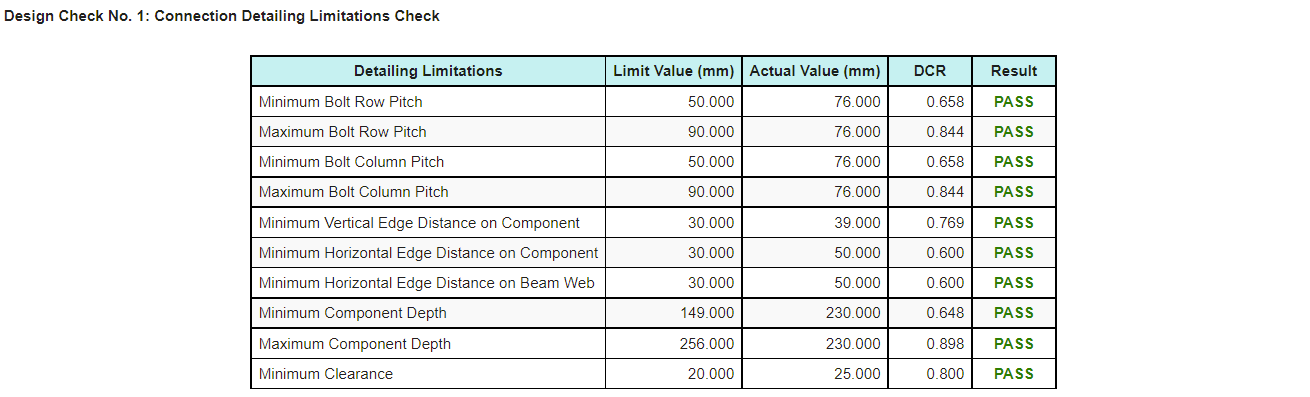
Detailing limitations, the fit-up checks on the connections, are included in the AS connection design. Most of them are based on ASI Design Guides 3-5, while some follow an intuitive engineering approach.
These checks catch the connection that satisfies every strength calculation and still cannot be built or erected, which is a failure mode that strength checks alone will not find.
A pass or fail result for the detailing limitations appears on the Results tab, so it can be identified quickly. O relatório de cálculo também produz uma tabela, mostrado abaixo, so the item that needs to be modified is easy to pick out.
Mais tipos de conexão
Should you wish to see more connection types added under AS 4100, você pode entrar em contato Suporte SkyCiv.
Experimente agora
Pick a web side plate, placa final flexível, single angle or double angle, entre no seu raio, support and loads, and the module returns every check with its utilization ratio and the reference behind it, along with the detailing limitation table. Ele roda no navegador, sem nada para instalar, and you can do it without an account.
You can also reach it through the Calculadora gratuita de projeto de conexão de aço.
Inscreva-se na conta gratuita
Uma conta gratuita permite salvar e recarregar seus arquivos de conexão, que a ferramenta gratuita não. It also gives you access to the rest of SkyCiv’s software estrutural, incluindo 3D Estrutural.
Projeto de Conexão Independente
Deseja usar apenas o módulo de design de conexão? Clique no botão abaixo para o preço independente.
