
Extended single plate connection design to AISC 360 is the shear tab procedure for a plate that reaches well past the support, usually so the beam can frame into a column web and clear the column flanges. You check the bolt group for the full eccentricity, the plate thickness for ductility, bolt bearing and tear-out on the plate and the beam web, cisalhamento de bloco, shear yielding and rupture, plate flexure and buckling, shear and flexure interaction, and the weld to the support. The long plate makes the bolt group eccentricity and the plate bending much larger than in a conventional shear tab, and that is what drives the design.
Esta página funciona como um exemplo real do início ao fim: a W24x55 beam framing into the web of a W14x90 column, com um 100 reação kip LRFD, through a 3/8 em x 13 em x 21 in A36 plate with fourteen 3/4 in A325-N bolts in two columns of seven. O projeto é AISC 360-16 e o Manual AISC 15ª Edição. Cada equação é escrita com seus números, na mesma ordem da planilha de cálculo AISC que o Projeto de conexões SkyCiv módulo produz para esta conexão.
What is an extended single plate connection?
An extended single plate connection is a shear tab that is longer than the conventional configuration allows. The plate is shop welded to the support and field bolted to the beam web, as with any single plate, but the bolts sit far enough from the weld that the AISC Manual’s simplified Table 10-9 approach no longer applies. It is still a simple connection under AISC 360-16 B3.4, então é detalhado girar em vez de resistir ao momento.
The most common use is a beam framing into a column web. The beam end has to sit outside the column flanges, so the plate reaches out from the web to meet it. In this example the beam end is 7 3/4 in from the column web. A plate that long bends a lot more than a short tab, so the bolt group is designed for the full eccentricity and the plate is checked for buckling as well as yielding. It is one type of conexão de cisalhamento, alongside the conexão de ângulo duplo, a conexão de ângulo único e o cisalhamento conexão da placa final. Você pode verificar este exemplo diretamente no calculadora de conexão de placa única, which covers both the conventional and extended configurations.
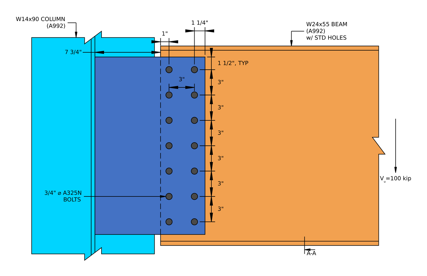
Elevação da conexão de exemplo. The beam end sits 7 3/4 in from the column web, outside the column flanges, and the first bolt column is 1 in in from the beam end.
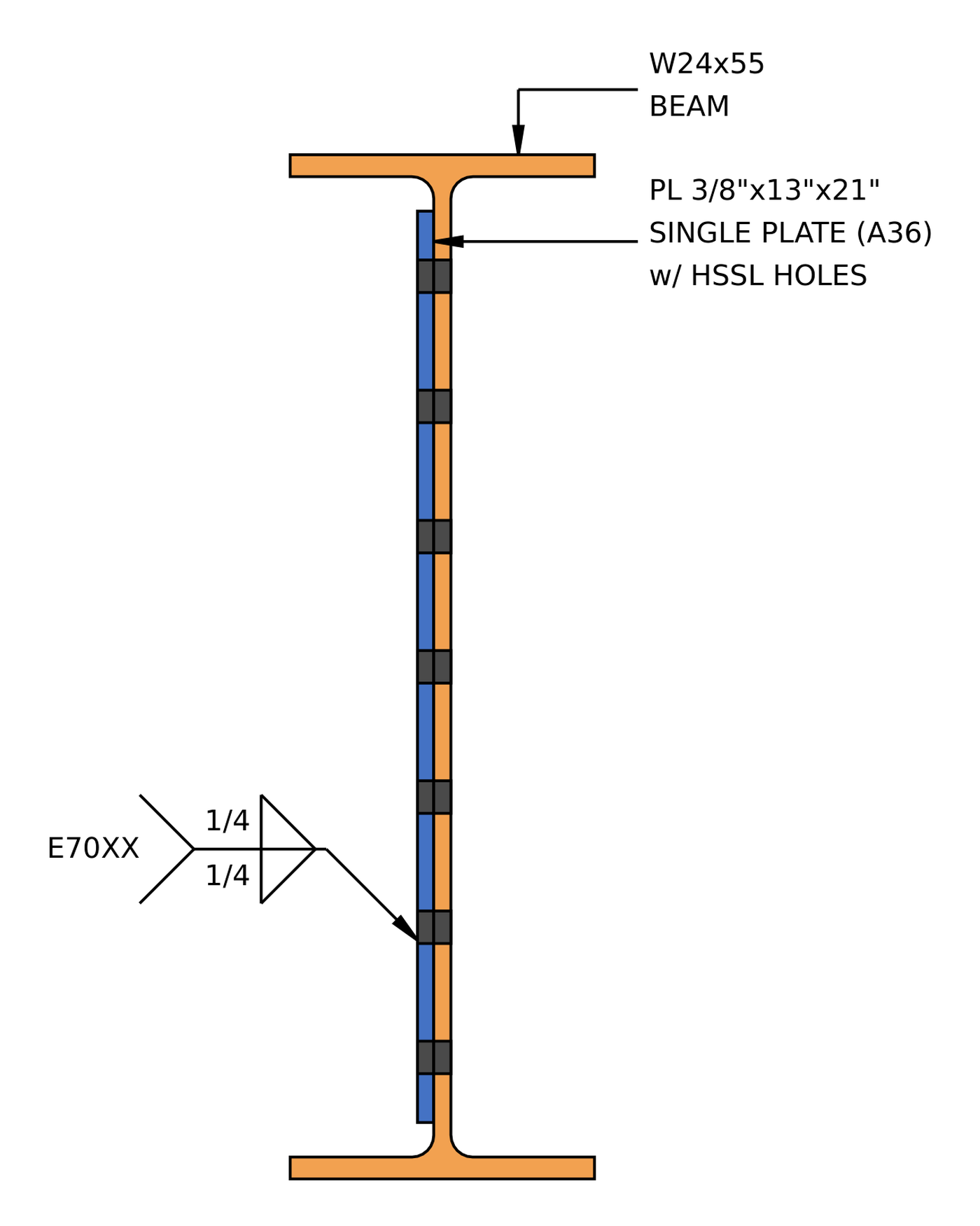
Seção A-A. A placa possui furos horizontais com fendas curtas e um 1/4 in fillet weld on both sides to the column web.
How do you design an extended single plate connection? As etapas em resumo
- Verifique os limites de detalhamento na viga: espaçamento do parafuso, distâncias de borda, profundidade da placa.
- Find the bolt group shear strength by the instantaneous center of rotation, for the full eccentricity.
- Verifique a ductilidade da placa: the plate must not be stronger in bending than the bolt group.
- Verifique o rolamento do parafuso e o rasgo na placa.
- Verifique o rolamento do parafuso e o rompimento na alma da viga.
- Combinar cisalhamento, rolamento e arrancamento por parafuso para a resistência efetiva do grupo.
- Verifique o cisalhamento do bloco da placa.
- Verifique o escoamento por cisalhamento e a ruptura por cisalhamento da placa.
- Check plate flexure and buckling using the double coped beam procedure.
- Check shear and flexure interaction for yielding.
- Check shear and flexure interaction for rupture.
- Verifique o limite de detalhamento no suporte.
- Check the weld size needed to develop the plate.
- Check the weld strength to the column web.
Entradas de design para este exemplo
O código de projeto é AISC 360-16 LRFD. As propriedades da seção são do Manual AISC.
| Item | Símbolo | Valor |
|---|---|---|
| Cisalhamento vertical fatorado | [mathin] V_{u} [mathin] | 100 kip |
| Feixe | W24x55, A992 | |
| Profundidade do feixe | [mathin] d_{bm} [mathin] | 23.6 no |
| Espessura da teia da viga | [mathin] t_{wb} [mathin] | 0.395 no |
| Largura do flange da viga / grossura | [mathin] b_{fb},\ t_{fb} [mathin] | 7.01 no / 0.505 no |
| Área do feixe | [mathin] A_{bm} [mathin] | 16.2 em² |
| Rendimento do feixe / tensão de tração | [mathin] F_{yb},\ F_{ub} [mathin] | 50 ksi / 65 ksi |
| Coluna | W14x90, A992 | |
| Column depth / espessura da teia | [mathin] d_{sup},\ t_{ws} [mathin] | 14 no / 0.44 no |
| Column flange width / grossura | [mathin] b_{fs},\ t_{fs} [mathin] | 14.5 no / 0.71 no |
| Área da coluna | [mathin] A_{sup} [mathin] | 26.5 em² |
| Rendimento da coluna / tensão de tração | [mathin] F_{ys},\ F_{us} [mathin] | 50 ksi / 65 ksi |
| Módulo de elasticidade | [mathin] E [mathin] | 29000 ksi |
| Item | Símbolo | Valor |
|---|---|---|
| Prato (placa única) | PT 3/8 x 13 x 21, A36 | |
| Largura da placa / profundidade / grossura | [mathin] b_{p},\ d_{p},\ t_{p} [mathin] | 13 no / 21 no / 0.375 no |
| Rendimento da placa / tensão de tração | [mathin] F_{yp},\ F_{up} [mathin] | 36 ksi / 58 ksi |
| Parafusos | 3/4 em A325-N, cisalhamento simples | |
| Diâmetro do parafuso | [mathin] d_{b} [mathin] | 0.75 no |
| Tensão nominal do parafuso / tensão de cisalhamento | [mathin] F_{nt},\ F_{nv} [mathin] | 90 ksi / 54 ksi |
| Planos de cisalhamento | [mathin] N_{s} [mathin] | 1 |
| Buracos na placa / feixe | Horizontal com fenda curta (HSSL) / padrão (DST) | |
| Soldar | 1/4 em filé, ambos os lados, E70XX | |
| Tamanho da solda / força de enchimento | [mathin] W,\ F_{EXX} [mathin] | 0.25 no / 70 ksi |
| Geometria | Símbolo | Valor |
|---|---|---|
| Linhas de parafusos / espaçamento entre linhas | [mathin] n_{r},\ s_{r} [mathin] | 7 / 3 no |
| Colunas de parafuso / espaçamento entre colunas | [mathin] n_{c},\ s_{c} [mathin] | 2 / 3 no |
| Beam web clearance (column web to beam end) | [mathin] clr [mathin] | 7.75 no |
| Distância horizontal da borda na alma da viga | [mathin] L_{eh,bm} [mathin] | 1 no |
| Distância horizontal da borda na placa | [mathin] L_{eh,pl} [mathin] | 1.25 no |
| Distância vertical da borda na placa | [mathin] L_{ev,pl} [mathin] | 1.5 no |
| Bolt group eccentricity | [mathin] e [mathin] | 10.25 no |
The plate width adds up from the drawing: 7.75 in to the beam end, 1 in to the first bolt column, 3 in between columns and 1.25 in to the plate edge, 13 in in total. The plate depth is the two 1.5 in edge distances plus six 3 in spaces, 21 no.
Passo 1: Limites de detalhamento no lado da viga (AISC 360-16 J3.3, J3.4, J3.5)
Antes de qualquer verificação de força, o layout do parafuso deve ser edificável e corresponder às suposições por trás das equações de resistência. Parafusos muito próximos rasgam entre os furos, bordas muito próximas rasgam, e uma placa muito curta ou muito profunda altera a forma como a conexão gira.
Para 3/4 no parafuso o espaçamento mínimo é [mathin] 2\tfrac{2}{3} d_{b} = 2\,in [mathin] (J3.3) e a distância mínima da borda é 1 no (Tabela J3.4). The plate has horizontal short slots, and its horizontal edge distance is measured from the end of the slot, então o incremento da Tabela J3.5 de 1/8 in raises its minimum to 1.125 no. A profundidade da placa deve ser pelo menos metade da dimensão T da viga, 20 3/4 in for a W24x55, então a conexão é rígida o suficiente para apoiar a extremidade da viga, and it must also fit within the beam web.
| Limite de detalhamento | Limite (no) | Real (no) | DCR | Resultado |
|---|---|---|---|---|
| Espaçamento mínimo entre linhas de parafusos | 2.000 | 3.000 | 0.667 | cdot K_a |
| Espaçamento máximo entre linhas de parafusos | 6.000 | 3.000 | 0.500 | cdot K_a |
| Espaçamento mínimo entre colunas de parafusos | 2.000 | 3.000 | 0.667 | cdot K_a |
| Espaçamento máximo entre colunas de parafusos | 6.000 | 3.000 | 0.500 | cdot K_a |
| Distância mínima da borda vertical da placa | 1.000 | 1.500 | 0.667 | cdot K_a |
| Distância mínima da borda horizontal da placa | 1.125 | 1.250 | 0.900 | cdot K_a |
| Distância mínima da borda horizontal do feixe | 1.000 | 1.000 | 1.000 | cdot K_a |
| Profundidade mínima de conexão | 10.375 | 21.000 | 0.494 | cdot K_a |
| Profundidade máxima de conexão | 21.375 | 21.000 | 0.982 | cdot K_a |
Para um limite mínimo, a relação é o limite sobre o real, e no máximo é real acima do limite. The governing row is the horizontal edge distance on the beam web, which sits exactly at the 1 no mínimo:
[math] DCR = \frac{d}{c} = \frac{(1)}{(1)} = 1 [math]
DCR = 1.000 ≤ 1.0, OK
The plate depth is also close to its upper limit at 0.982. A 21 in plate with seven rows is about as deep as this beam can take.
Passo 2: Resistência ao cisalhamento do grupo de parafusos pelo centro de rotação instantâneo (AISC 360-16 J3.6)
The beam reaction reaches the plate at the bolt group, a long way from the weld, so the bolts carry a large moment as well as the shear. O centro instantâneo de rotação (ICOR) método encontra o ponto em torno do qual o grupo de parafusos gira e transforma isso em um coeficiente C, qual é quantos parafusos’ valor da resistência ao cisalhamento que o grupo realmente oferece.
Excentricidade de design
For a conventional single plate, Tabela Manual AISC 10-9 lets you design the bolts for a reduced eccentricity. That table does not cover the extended configuration, so the bolt group is designed for the full distance from the weld line to the centroid of the bolt group. Here that is the beam clearance, plus the edge distance to the first bolt column, plus half the column spacing:
[math] e = clr + L_{eh,bm} + \frac{s_{c}}{2} = 7.75\,in + 1\,in + \frac{3\,in}{2} = 10.25\,in [math]
Força de um parafuso
Com [mathin] \phi = 0.75 [mathin], [mathin] F_{nv} = 54\,ksi [mathin], [mathin] d_{b} = 0.75\,in [mathin] e [mathin] N_{s} = 1 [mathin]:
[math] \phi r_{v} = \phi\, F_{nv}\, \frac{\pi}{4} \left( d_{b} \right)^{2} N_{s}\, h_{f} = 17.892\,kip [math]
Aqui [mathin] h_{f} = 1 [mathin] porque não há enchimentos (AISC 360-16 J5.2(uma)):
[math] h_{f} = 0.85 \lt 1 – (0.4) \times \left( (0\,in) – (0.25\,in) \right) \le 1 \;\Rightarrow\; h_{f} = 1 [math]
Localizando o centro instantâneo
Parafuso 1 is at the bottom-left corner of the group, com as coordenadas abaixo. O IC é encontrado por iteração, usando a curva carga-deformação da Equação Manual AISC (7-1) nas páginas 7-6 para 7-8. A cálculo de grupo de parafusos usando ICOR percorre essa iteração na íntegra.
| Parafuso | x (no) | Y (no) |
|---|---|---|
| 1 | 0.00 | 0.00 |
| 2 | 0.00 | 3.00 |
| 3 | 0.00 | 6.00 |
| 4 | 0.00 | 9.00 |
| 5 | 0.00 | 12.00 |
| 6 | 0.00 | 15.00 |
| 7 | 0.00 | 18.00 |
| 8 | 3.00 | 0.00 |
| 9 | 3.00 | 3.00 |
| 10 | 3.00 | 6.00 |
| 11 | 3.00 | 9.00 |
| 12 | 3.00 | 12.00 |
| 13 | 3.00 | 15.00 |
| 14 | 3.00 | 18.00 |
A iteração converge com o IC em:
[math] x_{ic} = -1.3636\,in, \qquad y_{ic} = 9\,in [math]
The IC sits level with the middle row and just outside the left bolt column. As reações do parafuso naquele local são:
| Parafuso | R (kip) | Detalhes e parâmetros do modelo (kip) | Ry (kip) | Mn (frango em) |
|---|---|---|---|---|
| 1 | 17.44 | 17.24 | 2.61 | 158.76 |
| 2 | 16.64 | 16.23 | 3.69 | 102.40 |
| 3 | 14.40 | 13.11 | 5.96 | 47.45 |
| 4 | 10.37 | 0.00 | 10.37 | 14.15 |
| 5 | 14.40 | -13.11 | 5.96 | 47.45 |
| 6 | 16.64 | -16.23 | 3.69 | 102.40 |
| 7 | 17.44 | -17.24 | 2.61 | 158.76 |
| 8 | 17.56 | 15.80 | 7.66 | 175.65 |
| 9 | 17.09 | 13.82 | 10.05 | 126.77 |
| 10 | 16.20 | 9.18 | 13.35 | 85.78 |
| 11 | 15.53 | 0.00 | 15.53 | 67.77 |
| 12 | 16.20 | -9.18 | 13.35 | 85.78 |
| 13 | 17.09 | -13.82 | 10.05 | 126.77 |
| 14 | 17.56 | -15.80 | 7.66 | 175.65 |
Isso dá os dois coeficientes usados no resto do projeto:
[math] C = 6.29 \qquad C’ = 72.195\,in [math]
Fourteen bolts deliver only 6.29 parafusos’ worth of vertical shear at a 10.25 in eccentricity, so more than half the group’s concentric strength goes into resisting the moment. C’ é o coeficiente apenas para o momento, qual a ductilidade é verificada na Etapa 3 usa.
Força do grupo de parafusos
[math] \phi R_{n} = \phi\, F_{nv}\, \frac{\pi}{4} \left( d_{b} \right)^{2} N_{s}\, C\, h_{f} [math]
[math] \phi R_{n} = (0.75) \times (54\,ksi) \times \frac{\pi}{4} \times \left( (0.75\,in) \right)^{2} \times (1) \times (6.29) \times (1) [math]
[math] \phi R_{n} = 112.54\,kip [math]
DCR = 100 kip / 112.54 kip = 0.889 < 1.0, OK
Passo 3: Ductilidade da placa, espessura máxima da placa (Eq Manual AISC. 10-3, 10-4)
Uma aba de cisalhamento deve girar conforme a viga desvia. If the plate is stronger in bending than the bolt group is in shear, os parafusos quebram antes que a placa ceda, que é de repente, falha frágil. Limitar a espessura da placa garante que a placa ceda primeiro. In the extended configuration this check is always required.
Primeiro, a resistência ao momento do grupo de parafusos, usando [mathin] C’ = 72.195\,in [mathin] da etapa 2 e [mathin] F_{nv} = 54\,ksi [mathin]:
[math] M_{max} = \frac{F_{nv}}{0.9}\, \frac{\pi}{4}\, d_{b}^{2}\, C’ [math]
[math] M_{max} = \frac{(54\,ksi)}{0.9} \times \frac{\pi}{4} \times (0.75\,in)^{2} \times (72.195\,in) = 159.47\,kip\text{-}ft [math]
Então a placa mais espessa cujo momento plástico não excede, com [mathin] F_{yp} = 36\,ksi [mathin] e [mathin] d_{p} = 21\,in [mathin]:
[math] t_{max} = \frac{6\, M_{max}}{F_{yp}\, d_{p}^{2}} [math]
[math] t_{max} = \frac{6 \times (159.47\,kip\text{-}ft)}{(36\,ksi) \times (21\,in)^{2}} = 0.72323\,in [math]
DCR = 0.375 no / 0.72323 em = 0.519 < 1.0, OK
A 3/8 in plate is about half the limit. Fourteen bolts give the group a large moment strength, so there is plenty of room here.
Passo 4: Rolamento do parafuso e remoção na placa única (AISC 360-16 J3.10)
Cada parafuso empurra para baixo a borda do seu furo na placa. A placa se deforma no furo (consequência, limitado em 2.4 d t Fu) ou rasga uma tira para o próximo buraco ou para a borda inferior (arrancar, 1.2 lc t Fu). The bottom bolt in each column has the shortest clear distance, então é o fraco.
The slots run horizontally and the load is vertical, so the hole dimension across the member length is the standard [mathin] d_{h} = 0.8125\,in [mathin]. Distância livre para o parafuso de borda, com [mathin] L_{ev,pl} = 1.5\,in [mathin]:
[math] l_{c1} = L_{ev,pl} – \frac{d_{h}}{2} = (1.5\,in) – \frac{(0.8125\,in)}{2} = 1.0938\,in [math]
Distância livre entre os parafusos, com [mathin] s_{r} = 3\,in [mathin]:
[math] l_{c2} = s_{r} – d_{h} = (3\,in) – (0.8125\,in) = 2.1875\,in [math]
Onde [mathin] t_{p} = 0.375\,in [mathin], [mathin] F_{up} = 58\,ksi [mathin], [mathin] C = 6.29 [mathin], [mathin] n_{r} = 7 [mathin] e [mathin] \phi = 0.75 [mathin]. The bracket is the strength of one line of seven bolts, and the factor C / n_r scales it for the eccentric group of two lines:
[math] \phi R_{n} = \phi \left[ \min\left(1.2\, l_{c1},\, 2.4\, d_{b}\right) t_{p} F_{up} + \min\left(1.2\, l_{c2},\, 2.4\, d_{b}\right) t_{p} F_{up} \left( n_{r} – 1 \right) \right] \left( \frac{C}{n_{r}} \right) [math]
[math] \phi R_{n} = (0.75) \times \left[ \min\left(1.2 \times (1.0938\,in),\, 2.4 \times (0.75\,in)\right) \times (0.375\,in) \times (58\,ksi) + \min\left(1.2 \times (2.1875\,in),\, 2.4 \times (0.75\,in)\right) \times (0.375\,in) \times (58\,ksi) \times \left( (7) – 1 \right) \right] \times \left( \frac{(6.29)}{(7)} \right) [math]
[math] \phi R_{n} = 177.54\,kip [math]
DCR = 100 kip / 177.54 kip = 0.563 < 1.0, OK
O rasgo controla o parafuso da borda, porque 1.2 lc1 é menor que 2.4 banco de dados. The inner bolts are capped by bearing.
Passo 5: Rolamento do parafuso e remoção na alma da viga (AISC 360-16 J3.10)
A mesma verificação se aplica à alma da viga. The beam is not coped and its flanges are far from the bolts, então não há borda para rasgar, e cada parafuso funciona como um parafuso interno.
[math] l_{c2} = s_{r} – d_{h} = (3\,in) – (0.8125\,in) = 2.1875\,in [math]
Onde [mathin] t_{wb} = 0.395\,in [mathin], [mathin] F_{ub} = 65\,ksi [mathin] e [mathin] C = 6.29 [mathin]:
[math] \phi R_{n} = \phi\, \min\left(1.2\, l_{c2},\, 2.4\, d_{b}\right) t_{wb} F_{ub}\, C [math]
[math] \phi R_{n} = (0.75) \times \min\left(1.2 \times (2.1875\,in),\, 2.4 \times (0.75\,in)\right) \times (0.395\,in) \times (65\,ksi) \times (6.29) [math]
[math] \phi R_{n} = 218.02\,kip [math]
DCR = 100 kip / 218.02 kip = 0.459 < 1.0, OK
A 0.395 in web is thicker than the plate and has a higher tensile strength, so it is the stronger ply in this connection.
Passo 6: Resistência efetiva do grupo de parafusos (AISC 360-16 Comentário J3.6)
Cisalhamento de parafuso, rolamento e arrancamento não são verificações separadas. Cada parafuso fornece o mínimo de sua resistência ao cisalhamento e sua resistência ao rolamento ou ao rasgo em cada camada pela qual passa, e a força do grupo é a soma desses valores por parafuso, scaled for the eccentricity.
Resistência de um parafuso em cisalhamento simples:
[math] \phi r_{v} = \phi\, F_{nv}\, \frac{\pi}{4} \left( d_{b} \right)^{2} N_{s}\, h_{f} = (0.75) \times (54\,ksi) \times \frac{\pi}{4} \times \left( (0.75\,in) \right)^{2} \times (1) \times (1) = 17.892\,kip [math]
Bearing and tear-out of one bolt on the plate, for the edge bolt and an inner bolt:
[math] \phi r_{n1e} = \phi\, \min\left(1.2\, l_{c1},\, 2.4\, d_{b}\right) t_{p} F_{up} = (0.75) \times \min\left(1.2 \times (1.0938\,in),\, 2.4 \times (0.75\,in)\right) \times (0.375\,in) \times (58\,ksi) = 21.41\,kip [math]
[math] \phi r_{n1i} = \phi\, \min\left(1.2\, l_{c2},\, 2.4\, d_{b}\right) t_{p} F_{up} = (0.75) \times \min\left(1.2 \times (2.1875\,in),\, 2.4 \times (0.75\,in)\right) \times (0.375\,in) \times (58\,ksi) = 29.363\,kip [math]
Bearing of one bolt on the beam web:
[math] \phi r_{n2} = \phi\, \min\left(1.2\, l_{c2},\, 2.4\, d_{b}\right) t_{wb} F_{ub} = (0.75) \times \min\left(1.2 \times (2.1875\,in),\, 2.4 \times (0.75\,in)\right) \times (0.395\,in) \times (65\,ksi) = 34.661\,kip [math]
Bolts are numbered from the top of each line, então parafuso 7 é o parafuso de borda na placa:
[math] \phi r_{eff,1} = \min\left( \phi r_{v},\, \phi r_{n1i},\, \phi r_{n2} \right) = \min\left( (17.892\,kip),\, (29.363\,kip),\, (34.661\,kip) \right) = 17.892\,kip [math]
[math] \phi r_{eff,2} = \min\left( \phi r_{v},\, \phi r_{n1e},\, \phi r_{n2} \right) = \min\left( (17.892\,kip),\, (21.41\,kip),\, (34.661\,kip) \right) = 17.892\,kip [math]
| Parafuso | Cisalhamento de parafuso (kip) | Consequência / arrancar, placa (kip) | Consequência / arrancar, teia de feixe (kip) | Força efetiva (kip) |
|---|---|---|---|---|
| 1 | 17.89 | 29.36 | 34.66 | 17.89 |
| 2 | 17.89 | 29.36 | 34.66 | 17.89 |
| 3 | 17.89 | 29.36 | 34.66 | 17.89 |
| 4 | 17.89 | 29.36 | 34.66 | 17.89 |
| 5 | 17.89 | 29.36 | 34.66 | 17.89 |
| 6 | 17.89 | 29.36 | 34.66 | 17.89 |
| 7 | 17.89 | 21.41 | 34.66 | 17.89 |
Sum over one line, com [mathin] n_{1} = 6 [mathin] bolts at the inner value and [mathin] n_{2} = 1 [mathin] at the edge value:
[math] \sum \phi r_{eff} = n_{1}\, \phi r_{eff,1} + n_{2}\, \phi r_{eff,2} = (6) \times (17.892\,kip) + (1) \times (17.892\,kip) = 125.25\,kip [math]
[math] \phi R_{n,eff} = \left( \frac{C}{n_{r}} \right) \sum \phi r_{eff} = \left( \frac{(6.29)}{(7)} \right) \times (125.25\,kip) = 112.54\,kip [math]
DCR = 100 kip / 112.54 kip = 0.889 < 1.0, OK
Bolt shear governs every bolt, então a resistência efetiva é igual à resistência ao cisalhamento do grupo de parafusos da Etapa 2. Você pode executar a mesma conexão no calculadora de design de conexão gratuita and try a larger bolt or a third bolt column to see how C moves.
Passo 7: Cisalhamento em bloco da placa única (AISC 360-16 J4.3)
A block of the plate can tear out around the bolt group: shear down the line of holes nearest the beam, plus tension across both bolt columns to the plate’s free edge. This is an L-shaped block.
Área líquida em tensão. O plano de tensão corre horizontalmente, ao longo das ranhuras, então ele usa o comprimento do slot [mathin] d_{h} = 1\,in [mathin], com [mathin] n_{c} = 2 [mathin], [mathin] s_{c} = 3\,in [mathin] e [mathin] L_{eh,pl} = 1.25\,in [mathin]. Cada buraco adiciona 1/16 em caso de danos durante o soco (B4.3):
[math] A_{nt} = t_{p} \left[ (n_{c}-1)\, s_{c} + L_{eh,pl} – (n_{c} – 0.5)\left( d_{h} + 0.0625\,in \right) \right] [math]
[math] A_{nt} = (0.375\,in) \times \left[ ((2)-1) \times (3\,in) + (1.25\,in) – ((2) – 0.5) \times ((1\,in) + (0.0625\,in)) \right] = 0.9961\,in^{2} [math]
Áreas bruta e líquida em cisalhamento. O plano de cisalhamento corre verticalmente, através dos slots, so the net area uses [mathin] d_{h} = 0.8125\,in [mathin]:
[math] A_{gv} = t_{p} \left[ L_{ev,pl} + (n_{r}-1)\, s_{r} \right] = (0.375\,in) \times \left[ (1.5\,in) + ((7)-1) \times (3\,in) \right] = 7.3125\,in^{2} [math]
[math] A_{nv} = t_{p} \left[ d_{p} – L_{ev,pl} – (n_{r} – 0.5)\left( d_{h} + 0.0625\,in \right) \right] [math]
[math] A_{nv} = (0.375\,in) \times \left[ (21\,in) – (1.5\,in) – ((7) – 0.5) \times ((0.8125\,in) + (0.0625\,in)) \right] = 5.1797\,in^{2} [math]
Resistência ao cisalhamento do bloco, com [mathin] F_{up} = 58\,ksi [mathin], [mathin] F_{yp} = 36\,ksi [mathin] e [mathin] \phi = 0.75 [mathin]. With two bolt columns the tension stress is not uniform, because the column nearest the free edge takes more of it, então [mathin] U_{bs} = 0.5 [mathin]:
[math] \phi R_{n} = \phi \left( 0.6\, F_{up} A_{nv} + U_{bs} F_{up} A_{nt} \le 0.6\, F_{yp} A_{gv} + U_{bs} F_{up} A_{nt} \right) [math]
[math] \phi R_{n} = (0.75) \times \left( 0.6 \times (58\,ksi) \times (5.1797\,in^{2}) + (0.5) \times (58\,ksi) \times (0.9961\,in^{2}) \le 0.6 \times (36\,ksi) \times (7.3125\,in^{2}) + (0.5) \times (58\,ksi) \times (0.9961\,in^{2}) \right) [math]
[math] \phi R_{n} = 140.13\,kip [math]
DCR = 100 kip / 140.13 kip = 0.714 < 1.0, OK
O lado de cisalhamento da equação governa. A36 tem uma baixa relação rendimento/tração, então o plano de cisalhamento bruto cede antes que o plano de cisalhamento líquido se rompa.
Passo 8: Cedência por cisalhamento e ruptura por cisalhamento da placa única (AISC 360-16 J4.2)
A reação completa passa através da placa como cisalhamento vertical. A seção bruta não deve ceder, e a seção da rede através dos furos dos parafusos não deve romper.
Cessamento ao cisalhamento (Eq. J4-3)
[math] A_{gv} = d_{p}\, t_{p} = (21\,in) \times (0.375\,in) = 7.875\,in^{2} [math]
[math] \phi R_{n,sy} = \phi\, 0.6\, F_{yp} A_{gv} = (1) \times 0.6 \times (36\,ksi) \times (7.875\,in^{2}) = 170.1\,kip [math]
Ruptura por cisalhamento (Eq. J4-4)
[math] A_{nv} = t_{p} \left[ d_{p} – n_{r}\left( d_{h} + 0.0625\,in \right) \right] = (0.375\,in) \times \left[ (21\,in) – (7) \times ((0.8125\,in) + (0.0625\,in)) \right] = 5.5781\,in^{2} [math]
[math] \phi R_{n,sr} = \phi\, 0.6\, F_{up} A_{nv} = (0.75) \times 0.6 \times (58\,ksi) \times (5.5781\,in^{2}) = 145.59\,kip [math]
[math] \phi R_{n} = \min\left( \phi R_{n,sy},\, \phi R_{n,sr} \right) = \min\left( (170.1\,kip),\, (145.59\,kip) \right) = 145.59\,kip [math]
DCR = 100 kip / 145.59 kip = 0.687 < 1.0, OK
The section is cut by the holes of one bolt column only, because the vertical section where shear is checked passes through a single line of holes.
Passo 9: Flexão de placa usando o procedimento de viga dupla (AISC 360-16 F11.2)
This is the check that sets an extended plate apart. The reaction acts at the bolts, 8.75 da solda, so the plate is a long cantilever in bending. Um profundo, thin plate over that length can buckle sideways before it yields. O Manual AISC trata disso com o procedimento para uma viga fixada em ambos os banzos, tratar a placa como uma viga com os flanges cortados. The unbraced length is the distance from the weld to the first bolt column, [mathin] L_{b} = clr + L_{eh,bm} = 7.75\,in + 1\,in = 8.75\,in [mathin].
Verificação de alcance
Onde [mathin] E = 29000\,ksi [mathin], [mathin] F_{yp} = 36\,ksi [mathin], [mathin] d_{p} = 21\,in [mathin] e [mathin] t_{p} = 0.375\,in [mathin]:
[math] \frac{L_{b} d}{t^{2}} = \frac{(8.75\,in) \times (21\,in)}{(0.375\,in)^{2}} = 1306.7 [math]
[math] \frac{0.08 E}{F_{y}} = \frac{0.08 \times (29000\,ksi)}{(36\,ksi)} = 64.444 \qquad \frac{1.9 E}{F_{y}} = \frac{1.9 \times (29000\,ksi)}{(36\,ksi)} = 1530.6 [math]
Então [mathin] \frac{0.08E}{F_{y}} \lt \frac{L_{b} d}{t^{2}} \le \frac{1.9E}{F_{y}} [mathin], Estimativa da capacidade da pilha. F11-2 se aplica. No 1306.7 the plate is close to the 1530.6 upper limit, beyond which Eq. F11-3 for elastic buckling would take over.
Módulos de seção da placa
[math] Z = \frac{t_{p} \left( d_{p} \right)^{2}}{4} = \frac{(0.375\,in) \times ((21\,in))^{2}}{4} = 41.344\,in^{3} [math]
[math] S = \frac{t_{p} \left( d_{p} \right)^{2}}{6} = \frac{(0.375\,in) \times ((21\,in))^{2}}{6} = 27.563\,in^{3} [math]
Fator de modificação da flambagem lateral-torcional (Eq Manual AISC. 9-15)
With no cope on the plate, [mathin] d_{ct} = 0\,in [mathin]:
[math] C_{b} = \left[ 3 + \ln\left( \frac{L_{b}}{d_{p}} \right) \right] \left( 1 – \frac{d_{ct}}{d_{p}} \right) \ge 1.84 [math]
[math] C_{b} = \left[ 3 + \ln\left( \frac{(8.75\,in)}{(21\,in)} \right) \right] \times \left( 1 – \frac{(0\,in)}{(21\,in)} \right) \ge 1.84 [math]
[math] C_{b} = 2.1245 [math]
Cedência flexural e resistência à flambagem
Com [mathin] \phi = 0.9 [mathin]:
[math] \phi M_{n} = \phi \left[ C_{b} \left[ 1.52 – 0.274 \left( \frac{L_{b} d}{t^{2}} \right) \left( \frac{F_{yp}}{E} \right) \right] F_{yp} S \le F_{yp} Z \right] [math]
[math] \phi M_{n} = (0.9) \times \left[ (2.1245) \times \left[ 1.52 – 0.274 \times ((1306.7)) \times \left( \frac{(36\,ksi)}{(29000\,ksi)} \right) \right] \times (36\,ksi) \times (27.563\,in^{3}) \le (36\,ksi) \times (41.344\,in^{3}) \right] [math]
[math] \phi M_{n} = 111.63\,kip\text{-}ft [math]
A tampa de momento de plástico governa: 111.63 kip-ft is [mathin] \phi F_{yp} Z [mathin]. With C_b above 2, the buckling expression comes out well above the cap, so even at L_b d / t² = 1306.7 the plate reaches its full plastic moment. The equivalent shear capacity at the bolts is:
[math] \phi V_{n,y} = \frac{\phi M_{n}}{L_{b}} = \frac{(111.63\,kip\text{-}ft)}{(8.75\,in)} = 153.09\,kip [math]
Ruptura flexural (Peça Manual AISC 15 Tabela 15-3, Papel 9 Eq. 9-4)
The net plastic section modulus removes the holes of one bolt column, com [mathin] d_{h} = 0.8125\,in [mathin], [mathin] s_{r} = 3\,in [mathin] e [mathin] n_{r} = 7 [mathin]. With an odd number of rows the last term applies:
[math] Z_{net} = \frac{t_{p} \left( d_{p} \right)^{2}}{4} – t_{p} \left( d_{h} + 0.0625\,in \right) s_{r} \left\lfloor \frac{n_{r}^{2}}{4} \right\rfloor – \left[ n_{r}\ \text{odd} \right] \frac{t_{p} \left( d_{h} + 0.0625\,in \right)^{2}}{4} [math]
[math] Z_{net} = \frac{(0.375\,in) \times ((21\,in))^{2}}{4} – (0.375\,in) \times ((0.8125\,in) + (0.0625\,in)) \times (3\,in) \times \left\lfloor \frac{(7)^{2}}{4} \right\rfloor – \left[ (7)\ \text{odd} \right] \times \frac{(0.375\,in) \times ((0.8125\,in) + (0.0625\,in))^{2}}{4} = 29.459\,in^{3} [math]
[math] \phi M_{n} = \phi\, F_{up} Z_{net} = (0.75) \times (58\,ksi) \times (29.459\,in^{3}) = 106.79\,kip\text{-}ft [math]
[math] \phi V_{n,r} = \frac{\phi M_{n}}{L_{b}} = \frac{(106.79\,kip\text{-}ft)}{(8.75\,in)} = 146.46\,kip [math]
Governando a capacidade flexural
[math] \phi V_{n} = \min\left( \phi V_{n,y},\, \phi V_{n,r} \right) = \min\left( (153.09\,kip),\, (146.46\,kip) \right) = 146.46\,kip [math]
DCR = 100 kip / 146.46 kip = 0.683 < 1.0, OK
Flexural rupture through the holes governs, by a small margin over yielding and buckling.
Passo 10: Interação de cisalhamento e flexão da placa única, rendendo (Peça Manual AISC 10)
A placa suporta cisalhamento e flexão na mesma seção ao mesmo tempo, então os dois têm que ser verificados juntos. O Manual usa uma interação circular. This one combines the flexural yielding strength from Step 9 with the shear yielding strength from Step 8.
[math] I_{nt} = \left( \frac{V_{u}}{\phi V_{n}} \right)^{2} + \left( \frac{V_{u}}{\phi R_{n,sy}} \right)^{2} [math]
[math] I_{nt} = \left( \frac{(100\,kip)}{(153.09\,kip)} \right)^{2} + \left( \frac{(100\,kip)}{(170.1\,kip)} \right)^{2} = 0.7723 [math]
DCR = 0.7723 / 1.0 = 0.772 < 1.0, OK
Passo 11: Interação de cisalhamento e flexão da placa única, ruptura (Peça Manual AISC 10)
The same interaction, with the flexural rupture strength from Step 9 and the shear rupture strength from Step 8. Both act on the net section through the holes.
[math] I_{nt} = \left( \frac{V_{u}}{\phi V_{n}} \right)^{2} + \left( \frac{V_{u}}{\phi R_{n,sr}} \right)^{2} [math]
[math] I_{nt} = \left( \frac{(100\,kip)}{(146.46\,kip)} \right)^{2} + \left( \frac{(100\,kip)}{(145.59\,kip)} \right)^{2} = 0.938 [math]
DCR = 0.938 / 1.0 = 0.938 < 1.0, OK
This is the highest strength ratio in the connection. Each of the two rupture checks on its own is under 0.69, but together they come close to the limit. That is typical of a long plate, where the moment at the bolt line is large compared with the shear.
Passo 12: Limite de detalhamento no lado do suporte
The fillet weld sits in the gap between the column web and the end of the beam, so the weld cannot be larger than that clearance. With the beam held 7.75 in off the column web, this check has a lot of room.
[math] DCR = \frac{d}{c} = \frac{(0.25)}{(7.75)} = 0.032258 [math]
DCR = 0.032 < 1.0, OK
Passo 13: Solda necessária para desenvolver a placa única (Peça Manual AISC 10)
A verificação de ductilidade na Etapa 3 faz a placa ceder primeiro. Isso só funciona se a solda não falhar antes da placa falhar.. Duas soldas de filete, cada um pelo menos 5/8 da espessura da placa, develop the strength of the plate.
[math] W_{duc} = \frac{5}{8}\, t_{p} = \frac{5}{8} \times (0.375\,in) = 0.23438\,in [math]
DCR = 0.23438 no / 0.25 em = 0.938 < 1.0, OK
The nearest standard size above 0.234 em é 1/4 no, so this ratio is set by rounding up, not by the load.
Passo 14: Fillet weld capacity to the column web (AISC 360-16 J2.4)
Durar, as soldas têm que realizar a reação em si. Sua força depende do tamanho, comprimento e direção da carga. O metal base em cada lado da solda, here the plate and the column web, também pode limitar o quanto o tamanho da solda conta.
Limite do metal base no tamanho da solda (Eq Manual AISC. 9-2)
This is the largest weld size, em décimos sextos de polegada, que a parte conectada mais fina possa suportar. The plate is welded on both sides, então metade de sua espessura está disponível para cada solda. Com [mathin] t_{p} = 0.375\,in [mathin], [mathin] F_{up} = 58\,ksi [mathin], [mathin] t_{ws} = 0.44\,in [mathin] e [mathin] F_{us} = 65\,ksi [mathin]:
[math] D_{max} = \frac{\frac{t_{p}}{2} F_{up} \le t_{ws} F_{us}}{3.09\,kip/in \times \left( F_{EXX} / 70\,ksi \right)} [math]
[math] D_{max} = \frac{(0.1875\,in) \times (58\,ksi) \le (0.44\,in) \times (65\,ksi)}{(3.09\,kip/in) \times (1)} = 3.5194 [math]
So only 3.52/16 no, sobre 0.220 no, do 1/4 in weld can be counted. A 3/8 in A36 plate cannot develop a full 1/4 in weld on both faces, and the plate rather than the 0.44 in column web sets the limit.
Comprimento efetivo
Duas linhas de solda, cada um reduzido em 2W nas extremidades:
[math] L_{w} = 2 \left[ d_{p} – 2W \right] = 2 \times \left[ (21\,in) – 2 \times (0.25\,in) \right] = 41\,in [math]
Força de soldagem
A carga corre paralelamente às soldas, então [mathin] \theta = 0 [mathin] e não há aumento direcional. Com [mathin] F_{EXX} = 70\,ksi [mathin] e [mathin] \phi = 0.75 [mathin]:
[math] \phi R_{n} = \phi\, 0.6\, F_{EXX} \frac{\sqrt{2}}{2} \left( W \le \frac{D_{max}}{16} \right) \left[ 1 + 0.5 \left( \sin\theta \right)^{1.5} \right] L_{w} [math]
[math] \phi R_{n} = (0.75) \times 0.6 \times (70\,ksi) \times \frac{\sqrt{2}}{2} \times \left( (0.25\,in) \le \frac{(3.5194)}{(16)} \right) \times \left[ 1 + 0.5 \times (\sin(0))^{1.5} \right] \times (41\,in) [math]
[math] \phi R_{n} = 200.88\,kip [math]
DCR = 100 kip / 200.88 kip = 0.498 < 1.0, OK
Summary of the extended single plate connection design checks
| Verificação de projeto | Demanda | Capacidade | DCR | Resultado |
|---|---|---|---|---|
| Limites de detalhamento no lado da viga | 1.000 no | 1.000 no | 1.000 | cdot K_a |
| Cisalhamento de grupo de parafusos | 100.000 kip | 112.543 kip | 0.889 | cdot K_a |
| Ductilidade (espessura máxima da placa) | 0.375 no | 0.723 no | 0.519 | cdot K_a |
| Rolamento de parafuso e remoção, placa única | 100.000 kip | 177.544 kip | 0.563 | cdot K_a |
| Rolamento de parafuso e remoção, teia de feixe | 100.000 kip | 218.019 kip | 0.459 | cdot K_a |
| Resistência efetiva do grupo de parafusos | 100.000 kip | 112.543 kip | 0.889 | cdot K_a |
| Cisalhamento em bloco de placa única | 100.000 kip | 140.128 kip | 0.714 | cdot K_a |
| Cedência ao cisalhamento e ruptura de placa única | 100.000 kip | 145.589 kip | 0.687 | cdot K_a |
| Flexão da placa (procedimento duplo enfrentado) | 100.000 kip | 146.456 kip | 0.683 | cdot K_a |
| Interação de cisalhamento e flexão, rendendo | 0.772 | 1.000 | 0.772 | cdot K_a |
| Interação de cisalhamento e flexão, ruptura | 0.938 | 1.000 | 0.938 | cdot K_a |
| Detalhando limites no lado do suporte | 0.250 no | 7.750 no | 0.032 | cdot K_a |
| Soldar para desenvolver placa única | 0.234 no | 0.250 no | 0.938 | cdot K_a |
| Weld to support web | 100.000 kip | 200.877 kip | 0.498 | cdot K_a |
A conexão passa em todas as verificações. A proporção mais alta, 1.000, is a detailing limit: the bolts are exactly the minimum 1 in from the beam end, quanto pelo 21 in plate is at 0.982 of its maximum depth. Das verificações que comparam carga com capacidade, shear and flexure interaction for rupture governs at 0.938, followed by bolt group shear at 0.889. Both come from the 10.25 in eccentricity, which cuts the 14 bolts to 6.29 effective bolts and puts a large moment into the plate at the bolt line. The weld-to-develop ratio of 0.938 is a sizing rule, not a load check.
O que mudar se uma verificação falhar
- Cisalhamento do grupo de parafusos ou resistência efetiva: use a larger bolt or a stronger grade, such as A325-X (tópicos excluídos) or A490. Adding a bolt row raises C, but here the plate is already near its maximum depth, so a third bolt column is the other option.
- Interaction or plate flexure: use uma placa mais grossa, as long as the ductility check in Step 3 still passes. Reducing the beam clearance shortens L_b and the eccentricity, which helps every plate and bolt check.
- Ductilidade (t_max): use uma placa mais fina, or add bolts so the group’s moment strength rises. Uma placa mais espessa piora esta verificação.
- Rasgar no prato: increase the vertical edge distance below the bottom bolt row.
- Cisalhamento de bloco, shear yielding or shear rupture of the plate: use a thicker or deeper plate. A longer horizontal edge distance also adds to the block shear tension area.
- Soldar: the base metal limit caps the useful weld size at about 0.220 in for a 3/8 in A36 plate, so a bigger weld adds nothing. A thicker or higher-strength plate raises that cap.
- A different connection: if the plate cannot be made to work, uma conexão de ângulo duplo or a shear end plate with the beam coped to fit between the column flanges avoids the long cantilever altogether.
Perguntas frequentes
Qual é a diferença entre uma conexão de placa única convencional e estendida?
The conventional configuration in AISC Manual Part 10 covers a single vertical row of 2 para 12 parafusos, with the bolt line no more than 3 1/2 in from the weld and limits on edge distance and plate thickness. Within those limits you can use Table 10-9, with its reduced bolt eccentricity and no plate buckling check. Qualquer coisa fora deles, such as this plate with two bolt columns 8.75 dentro e 11.75 da solda, is the extended configuration. The bolt group is then designed for the full eccentricity, the plate thickness must pass the ductility check, and the plate is checked for buckling.
Why is the bolt eccentricity 10.25 no?
In the extended configuration the bolt group is designed for the distance from the weld line to the centroid of the bolts. That is the 7.75 in beam clearance, plus the 1 in edge distance to the first bolt column, plus half of the 3 in spacing between the two columns, 10.25 in in total.
Why does a beam framing into a column web need an extended plate?
The column flanges are in the way. A W14x90 flange is 14.5 em largura, so it projects about 7 in from the web on each side, and the beam end has to sit outside that line. The plate is welded to the column web and reaches out past the flange tips to the beam, which is why this example has a 7.75 in clearance and a 13 in wide plate. The other option is to cope the beam flanges so the beam fits between the column flanges, which lets you use a shorter, conventional plate.
Why is the block shear uniformity factor 0.5?
With two bolt columns, the tension across the block is not shared evenly. The bolt column closer to the free edge of the plate takes more of it. AISC 360-16 J4.3 and its Commentary use U_bs = 0.5 for non-uniform tension stress, and the AISC Manual applies that to single plates with more than one bolt column.
Why does only part of the 1/4 in weld count?
Manual Eq. 9-2 limits the weld size to what the base metal can carry. The plate is 3/8 em grosso, A36, and welded on both faces, so each weld can only be backed by half of it. That gives 3.52 sixteenths, or about 0.220 no, of usable weld size. A 1/4 in weld is still needed to meet the 5/8 t_p rule in Step 13, but its strength is calculated on the smaller size.
Why does shear and flexure interaction govern?
In a conventional tab the moment at the bolt line is small, so interaction rarely matters. Here the bolts are 8.75 da solda, so the moment is large. The plate’s flexural rupture strength (146.46 kip as equivalent shear) and its shear rupture strength (145.59 kip) are almost equal. Squaring and adding the two ratios gives 0.938, even though each one on its own is below 0.69.
Este exemplo segue a 15ª edição do AISC ou o Manual da 16ª edição do AISC?
Segue AISC 360-16 e o Manual AISC 15ª Edição, que está escrito em torno dessa Especificação. O Manual AISC 16ª Edição combina com o posterior 360-22 Especificação. The limit states for an extended single plate connection are the same in both, mas as referências de cláusula e página se movem, então compare-os com a edição que seu projeto usa.
Como isso mudaria para AISC ASD em vez de LRFD?
Os estados limites e as resistências nominais são idênticos. Com AISC ASD você compara a reação de nível de serviço com a resistência nominal dividida por um fator de segurança em vez de multiplicar por um fator de resistência. Um fator de resistência de 0.75 torna-se um fator de segurança de 2.00, rendimento de cisalhamento 1.00 torna-se 1.50, e flexão 0.90 torna-se 1.67. As combinações de carga também mudam, então a demanda é menor.
Design an extended single plate connection for free
Cada número nesta página vem de uma solução. Escolha a configuração de placa única, entre no seu raio, coluna, placa, parafusos e reação, e veja cada uma dessas verificações em seu navegador. Não há nada para instalar.
O módulo SkyCiv Connection Design é o software de design de conexão por trás deste exemplo. Fornece o relatório de cálculo completo com todas as equações e seus números, como as etapas acima, além de todas as capacidades e DCR, para AISC 360-16 (LRFD e ASD) e a norma AS 4100:2020. A calculadora de parafuso e calculadora de solda cubra o grupo de parafusos e verifique a soldagem por conta própria.
Referências
- AISC 360-16, correspondente às especificações para aço estrutural: B3.4, B4.3, F11.2 (Eq. F11-2), J2.4 (Eq. J2-4), J3.3, J3.4 (Tabela J3.4), J3.5 (Tabela J3.5), J3.6 (Eq. J3-1) e Comentário, J3.10 (Eq. J3-6a, J3-6c), J4.2 (Eq. J4-3, J4-4), J4.3 (Eq. J4-5), J5.2(uma).
- Manual de construção em aço AISC, 15ª edição: Papel 7, Páginas 7-6 para 7-8 (Eq. 7-1); Papel 9, Eq. 9-2, 9-4 e 9-15; Papel 10, Tabela 10-9, página 10-87 e página 10-89 (Eq. 10-3, 10-4); Papel 15, Tabela 15-3.
- Cálculo do grupo de parafusos usando ICOR
- Dimensionamento de ligações metálicas utilizando AISC 360-16
- Parafusos e soldas no design de conexão SkyCiv

Harold Munalem
gerente de produto, Projeto de Conexão
10+ anos em projetos de conexões de aço
LinkedIn
