
Double angle connection design to AISC 360 means checking two bolt groups and the angles between them against the beam end reaction. No lado da viga você verifica o cisalhamento do parafuso, bearing and tear-out on the angles and the beam web, cisalhamento de bloco, shear yielding and rupture of the angles, e flexão angular. On the support side you repeat those checks for the outstanding legs bolted to the column. Detalhando limites de espaçamento, distância da borda, gage and connection depth apply to both sides.
Esta página funciona como um exemplo real do início ao fim: a W16x26 beam framing into the flange of a W14x90 column, com um 50 reação kip LRFD, a pair of 2L4x3-1/2×1/4 angles and three rows of 3/4 in A325-N bolts on each side, projetado para AISC 360-16 e o Manual AISC 15ª Edição. Cada equação é escrita com seus números, na mesma ordem da planilha de cálculo AISC que o Projeto de conexões SkyCiv módulo produz para esta conexão.
What is a double angle connection?
A double angle connection is a pair of steel angles, um de cada lado da alma da viga, com uma perna aparafusada (ou soldado) à alma e a outra perna aparafusada ao membro de suporte. Transfere o cisalhamento final da viga e é classificada como uma ligação simples pelo AISC 360-16 B3.4, so the angles are detailed to flex rather than resist moment.
It is a common conexão de cisalhamento for beams framing into column flanges, column webs and girders. Because the beam web sits between two angles, the beam-side bolts work in double shear, and the connection is symmetric, so it does not twist the beam. As outras opções para o mesmo trabalho são o placa única (aba de cisalhamento) conexão, a conexão de ângulo único e o cisalhamento conexão da placa final. Você pode verificar este exemplo diretamente no double angle connection calculator.
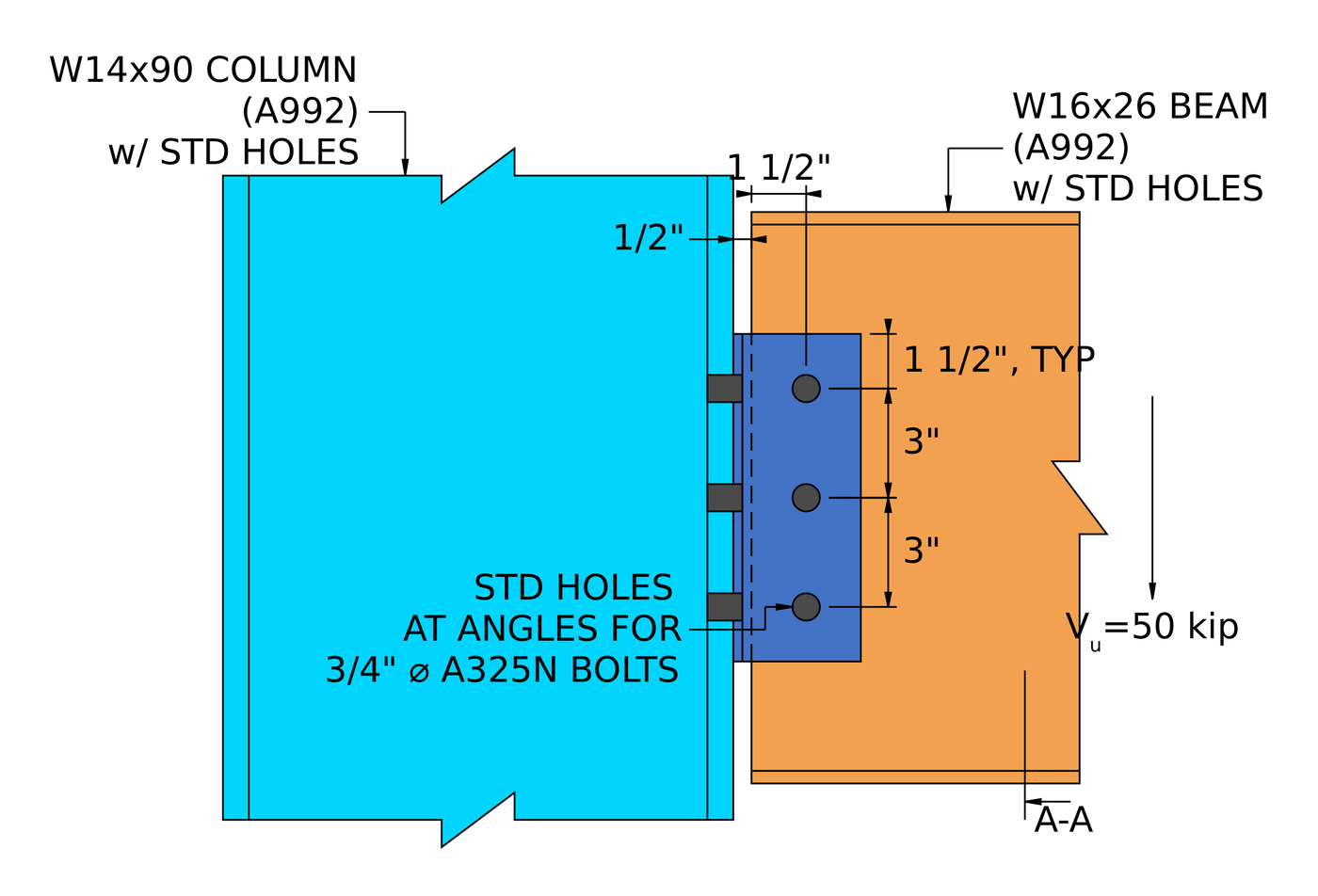
Elevação da conexão de exemplo. The angles are bolted to the column flange and to the beam web, com um 1/2 in clearance between the beam end and the column.
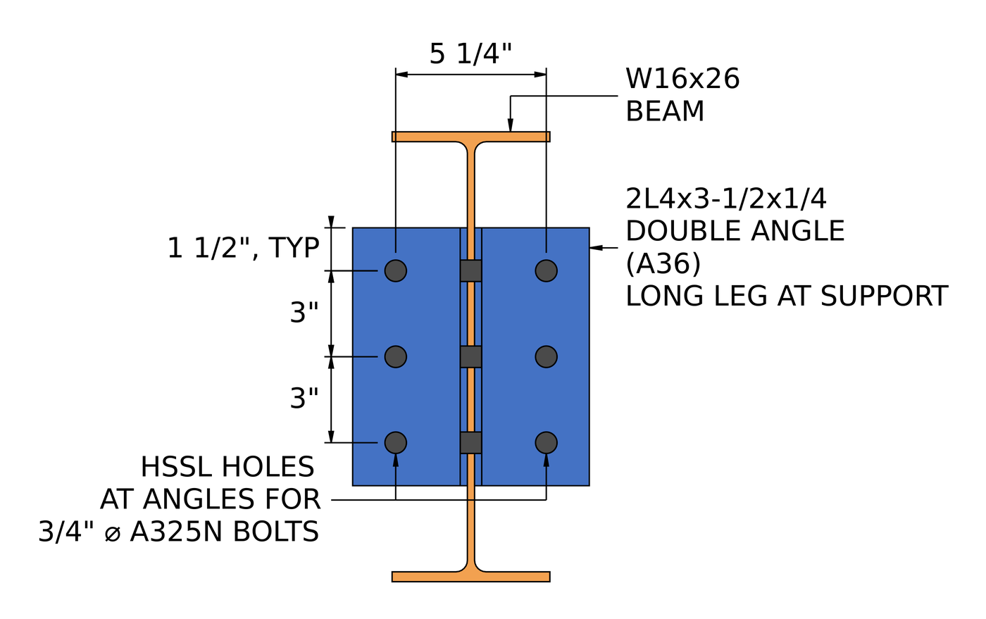
Seção A-A. The long legs are bolted to the column at a 5 1/4 em calibre, through horizontal short-slotted holes in the angles.
How do you design a double angle connection? As etapas em resumo
- Verifique os limites de detalhamento no lado da viga: espaçamento, distâncias de borda, profundidade, calibrar.
- Check the beam-side bolt group in double shear.
- Check bolt bearing and tear-out on the angles at the beam side.
- Verifique o rolamento do parafuso e o rompimento na alma da viga.
- Combinar cisalhamento, rolamento e destacável por parafuso no lado da viga.
- Check block shear of the angles at the beam side.
- Check shear yielding and shear rupture of the angles at the beam side.
- Verifique a flexão angular no lado da viga usando o procedimento duplo.
- Check shear and moment interaction of the angles at the beam side.
- Verifique os limites de detalhamento no lado do apoio.
- Check the support-side bolt group in single shear.
- Check bolt bearing and tear-out on the angles at the support side.
- Verifique o rolamento do parafuso e o rompimento do flange da coluna.
- Combinar cisalhamento, rolamento e destacável por parafuso no lado do suporte.
- Check block shear of the angles at the support side.
- Check shear yielding and shear rupture of the angles at the support side.
- Verifique a flexão angular no lado do suporte usando o procedimento duplo.
- Check shear and moment interaction of the angles at the support side.
Entradas de design para este exemplo
O código de projeto é AISC 360-16 LRFD. As propriedades da seção são do Manual AISC.
| Item | Símbolo | Valor |
|---|---|---|
| Cisalhamento vertical fatorado | [mathin] V_{u} [mathin] | 50 kip |
| Feixe | W16x26, A992 | |
| Profundidade do feixe | [mathin] d_{bm} [mathin] | 15.7 no |
| Espessura da teia da viga | [mathin] t_{wb} [mathin] | 0.25 no |
| Largura do flange da viga / grossura | [mathin] b_{fb},\ t_{fb} [mathin] | 5.5 no / 0.345 no |
| Área do feixe | [mathin] A_{bm} [mathin] | 7.68 em² |
| Rendimento do feixe / tensão de tração | [mathin] F_{yb},\ F_{ub} [mathin] | 50 ksi / 65 ksi |
| Coluna | W14x90, A992 | |
| Column depth / espessura da teia | [mathin] d_{sup},\ t_{ws} [mathin] | 14 no / 0.44 no |
| Column flange width / grossura | [mathin] b_{fs},\ t_{fs} [mathin] | 14.5 no / 0.71 no |
| Área da coluna | [mathin] A_{sup} [mathin] | 26.5 em² |
| Rendimento da coluna / tensão de tração | [mathin] F_{ys},\ F_{us} [mathin] | 50 ksi / 65 ksi |
| Módulo de elasticidade | [mathin] E [mathin] | 29000 ksi |
| Item | Símbolo | Valor |
|---|---|---|
| Ângulos | 2L4x3-1/2×1/4, A36, long leg at support | |
| Profundidade do ângulo | [mathin] d_{a} [mathin] | 9 no |
| Espessura do ângulo | [mathin] t_{a} [mathin] | 0.25 no |
| Largura da perna na trave / no suporte | [mathin] b_{a,NSL},\ b_{a,OSL} [mathin] | 3.5 no / 4 no |
| Rendimento angular / tensão de tração | [mathin] F_{ya},\ F_{ua} [mathin] | 36 ksi / 58 ksi |
| Parafusos (ambos os lados) | 3/4 em A325-N | |
| Diâmetro do parafuso | [mathin] d_{b} [mathin] | 0.75 no |
| Tensão nominal do parafuso / tensão de cisalhamento | [mathin] F_{nt},\ F_{nv} [mathin] | 90 ksi / 54 ksi |
| Planos de cisalhamento, lado da viga / lado de apoio | [mathin] N_{s} [mathin] | 2 / 1 |
| Furos no lado da viga (ângulo / feixe) | Padrão (DST) / padrão (DST) | |
| Furos no lado do suporte (ângulo / coluna) | Horizontal com fenda curta (HSSL) / padrão (DST) |
| Geometria | Símbolo | Lado da viga | Lado de suporte |
|---|---|---|---|
| Linhas de parafusos / espaçamento entre linhas | [mathin] n_{r},\ s_{r} [mathin] | 3 / 3 no | 3 / 3 no |
| Colunas de parafuso / espaçamento entre colunas | [mathin] n_{c},\ s_{c} [mathin] | 1 / 0 no | 1 / 0 no |
| Calibrar | [mathin] g [mathin] | 2 no | 5.25 no |
| Distância vertical da borda no ângulo | [mathin] L_{ev,a} [mathin] | 1.5 no | 1.5 no |
| Distância da borda horizontal no ângulo | [mathin] L_{eh,a} [mathin] | 1.5 no | 1.5 no |
| Excentricidade do parafuso | [mathin] e [mathin] | 2 no | 0 no |
| Folga da alma do feixe para a coluna | [mathin] clr [mathin] | 0.5 no |
Passo 1: Limites de detalhamento no lado da viga (AISC 360-16 J3.3, J3.4, J3.5)
Antes de qualquer verificação de força, o layout do parafuso deve ser edificável e corresponder às suposições por trás das equações de resistência. Parafusos muito próximos rasgam entre os furos, bordas muito próximas rasgam, and angles that are too short or too deep change how the connection rotates.
Para 3/4 no parafuso o espaçamento mínimo é [mathin] 2\tfrac{2}{3} d_{b} = 2\,in [mathin] (J3.3) e a distância mínima da borda é 1 no (Tabela J3.4). The maximum spacing is 24 times the thinner part, here the 1/4 in angle or the 1/4 in beam web, which gives 6 no (J3.5). The angles have to be at least half as deep as the beam’s T dimension, so they are stiff enough to brace the beam end, e não mais profundo do que a teia do feixe pode suportar. The bolt gage on the beam-side legs has to leave room to enter and tighten the bolts.
| Limite de detalhamento | Limite (no) | Real (no) | DCR | Resultado |
|---|---|---|---|---|
| Espaçamento mínimo entre linhas de parafusos | 2.000 | 3.000 | 0.667 | cdot K_a |
| Espaçamento máximo entre linhas de parafusos | 6.000 | 3.000 | 0.500 | cdot K_a |
| Distância mínima da borda vertical do ângulo | 1.000 | 1.500 | 0.667 | cdot K_a |
| Distância mínima da borda horizontal do ângulo | 1.000 | 1.500 | 0.667 | cdot K_a |
| Distância mínima da borda horizontal do feixe | 1.000 | 1.500 | 0.667 | cdot K_a |
| Profundidade mínima de conexão | 6.813 | 9.000 | 0.757 | cdot K_a |
| Profundidade máxima de conexão | 14.125 | 9.000 | 0.637 | cdot K_a |
| Minimum bolt gage for double angle | 1.375 | 2.000 | 0.688 | cdot K_a |
Para um limite mínimo, a relação é o limite sobre o real, e no máximo é real acima do limite. A linha governante é a profundidade mínima da conexão, metade do 13 5/8 in T dimension of the W16x26:
[math] DCR = \frac{d}{c} = \frac{6.8125\,in}{9\,in} = 0.75694 [math]
DCR = 0.757 < 1.0, OK
Passo 2: Cisalhamento do grupo de parafusos no lado da viga (AISC 360-16 J3.6)
The beam web is sandwiched between the two angles, so every beam-side bolt is in double shear. The bolt group has to carry the full reaction through those shear planes.
Coeficiente de grupo de parafusos
A reação atua 2 in from the beam-side bolt line, mas a excentricidade é ignorada aqui. Página do manual AISC 10-9 permite isso para uma única fileira vertical de parafusos com uma excentricidade não superior a 3 no, então o coeficiente do grupo de parafusos é simplesmente o número de parafusos:
[math] C = 3 [math]
Força do grupo de parafusos
Onde [mathin] \phi = 0.75 [mathin], [mathin] d_{b} = 0.75\,in [mathin], [mathin] F_{nv} = 54\,ksi [mathin] para um parafuso A325-N com roscas incluídas, [mathin] N_{s} = 2 [mathin] shear planes and [mathin] h_{f} [mathin] is the filler factor from J5.2(uma). There are no fillers, então:
[math] h_{f} = 0.85 \lt 1 – 0.4 \left( t – 0.25\,in \right) \le 1 [math]
[math] h_{f} = 0.85 \lt 1 – (0.4) \times \left( (0\,in) – (0.25\,in) \right) \le 1 [math]
[math] h_{f} = 1 [math]
[math] \phi R_{n} = \phi\, F_{nv}\, \frac{\pi}{4} \left( d_{b} \right)^{2} N_{s}\, C\, h_{f} [math]
[math] \phi R_{n} = (0.75) \times (54\,ksi) \times \frac{\pi}{4} \times \left( (0.75\,in) \right)^{2} \times (2) \times (3) \times (1) [math]
[math] \phi R_{n} = 107.35\,kip [math]
DCR = 50 kip / 107.35 kip = 0.466 < 1.0, OK
Passo 3: Bolt bearing and tear-out on the double angle at the beam side (AISC 360-16 J3.10)
Each beam-side bolt pushes on the edge of its hole in both angles. O ângulo se deforma no furo (consequência, limitado em 2.4 d t Fu) ou rasga uma tira para o próximo buraco ou para a borda inferior (arrancar, 1.2 lc t Fu). The beam pushes the bolts down, então o parafuso inferior, mais próximo da borda inferior do ângulo, é o fraco.
Distância livre para o parafuso de borda, com [mathin] L_{ev,a} = 1.5\,in [mathin] and the standard hole dimension [mathin] d_{h} = 0.8125\,in [mathin]:
[math] l_{c1} = L_{ev,a} – \frac{d_{h}}{2} = (1.5\,in) – \frac{(0.8125\,in)}{2} = 1.0938\,in [math]
Distância livre entre os parafusos internos, com [mathin] s_{r} = 3\,in [mathin]:
[math] l_{c2} = s_{r} – d_{h} = (3\,in) – (0.8125\,in) = 2.1875\,in [math]
Both angles bear on each bolt, so the ply thickness is [mathin] 2t_{a} = 0.5\,in [mathin], com [mathin] F_{ua} = 58\,ksi [mathin], [mathin] C = 3 [mathin] e [mathin] n_{r} = 3 [mathin]:
[math] \phi R_{n} = \phi \left[ \min\left(1.2\, l_{c1},\, 2.4\, d_{b}\right) 2t_{a} F_{ua} + \min\left(1.2\, l_{c2},\, 2.4\, d_{b}\right) 2t_{a} F_{ua} \left( n_{r} – 1 \right) \right] \left( \frac{C}{n_{r}} \right) [math]
[math] \phi R_{n} = (0.75) \times \left[ \min\left(1.2 \times (1.0938\,in),\, 2.4 \times (0.75\,in)\right) \times (0.5\,in) \times (58\,ksi) + \min\left(1.2 \times (2.1875\,in),\, 2.4 \times (0.75\,in)\right) \times (0.5\,in) \times (58\,ksi) \times \left( (3) – 1 \right) \right] \times \left( \frac{(3)}{(3)} \right) [math]
[math] \phi R_{n} = 106.85\,kip [math]
DCR = 50 kip / 106.85 kip = 0.468 < 1.0, OK
O rasgo controla o parafuso da borda, porque 1.2 lc1 é menor que 2.4 banco de dados. The inner bolts are limited by bearing.
Passo 4: Rolamento do parafuso e remoção na alma da viga (AISC 360-16 J3.10)
A mesma verificação se aplica à alma da viga, which is a single 1/4 in ply carrying all three bolts. The beam is not coped and its top flange is well clear of the bolts, so every bolt bears like an inner bolt.
[math] l_{c2} = s_{r} – d_{h} = (3\,in) – (0.8125\,in) = 2.1875\,in [math]
Onde [mathin] t_{wb} = 0.25\,in [mathin], [mathin] F_{ub} = 65\,ksi [mathin], [mathin] C = 3 [mathin] e [mathin] \phi = 0.75 [mathin]:
[math] \phi R_{n} = \phi\, \min\left(1.2\, l_{c2},\, 2.4\, d_{b}\right) t_{wb} F_{ub}\, C [math]
[math] \phi R_{n} = (0.75) \times \min\left(1.2 \times (2.1875\,in),\, 2.4 \times (0.75\,in)\right) \times (0.25\,in) \times (65\,ksi) \times (3) [math]
[math] \phi R_{n} = 65.813\,kip [math]
DCR = 50 kip / 65.813 kip = 0.760 < 1.0, OK
This is the highest strength ratio in the connection. The two angles give 0.5 in of A36 steel against the bolts, but the beam web is only 0.25 em grosso, so the web has about 60% of the angles’ bearing capacity even with the higher 65 ksi tensile strength.
Passo 5: Resistência efetiva do grupo de parafusos no lado da viga (AISC 360-16 Comentário J3.6)
Cisalhamento de parafuso, rolamento e arrancamento não são verificações separadas. Cada parafuso carrega o mínimo de sua resistência ao cisalhamento e sua resistência ao rolamento ou ao rasgo em cada camada pela qual passa, e a força do grupo é a soma desses valores por parafuso.
Strength of one bolt in double shear:
[math] \phi r_{v} = \phi\, F_{nv}\, \frac{\pi}{4} \left( d_{b} \right)^{2} N_{s}\, h_{f} [math]
[math] \phi r_{v} = (0.75) \times (54\,ksi) \times \frac{\pi}{4} \times \left( (0.75\,in) \right)^{2} \times (2) \times (1) = 35.785\,kip [math]
Bearing and tear-out of one bolt on the double angle, for the edge bolt and for an inner bolt:
[math] \phi r_{n1e} = \phi\, \min\left(1.2\, l_{c1},\, 2.4\, d_{b}\right) 2t_{a} F_{ua} [math]
[math] \phi r_{n1e} = (0.75) \times \min\left(1.2 \times (1.0938\,in),\, 2.4 \times (0.75\,in)\right) \times (0.5\,in) \times (58\,ksi) = 28.547\,kip [math]
[math] \phi r_{n1i} = \phi\, \min\left(1.2\, l_{c2},\, 2.4\, d_{b}\right) 2t_{a} F_{ua} [math]
[math] \phi r_{n1i} = (0.75) \times \min\left(1.2 \times (2.1875\,in),\, 2.4 \times (0.75\,in)\right) \times (0.5\,in) \times (58\,ksi) = 39.15\,kip [math]
Rolamento e arrancamento de um parafuso na alma da viga:
[math] \phi r_{n2} = \phi\, \min\left(1.2\, l_{c2},\, 2.4\, d_{b}\right) t_{wb} F_{ub} [math]
[math] \phi r_{n2} = (0.75) \times \min\left(1.2 \times (2.1875\,in),\, 2.4 \times (0.75\,in)\right) \times (0.25\,in) \times (65\,ksi) = 21.938\,kip [math]
Os parafusos são numerados a partir do topo da linha, então parafuso 3 is the edge bolt on the angles:
[math] \phi r_{eff,1} = \min\left( \phi r_{v},\, \phi r_{n1i},\, \phi r_{n2} \right) = \min\left( (35.785\,kip),\, (39.15\,kip),\, (21.938\,kip) \right) = 21.938\,kip [math]
[math] \phi r_{eff,2} = \min\left( \phi r_{v},\, \phi r_{n1e},\, \phi r_{n2} \right) = \min\left( (35.785\,kip),\, (28.547\,kip),\, (21.938\,kip) \right) = 21.938\,kip [math]
| Parafuso | Cisalhamento de parafuso (kip) | Consequência / arrancar, ângulo duplo (kip) | Consequência / arrancar, teia de feixe (kip) | Força efetiva (kip) |
|---|---|---|---|---|
| 1 | 35.78 | 39.15 | 21.94 | 21.94 |
| 2 | 35.78 | 39.15 | 21.94 | 21.94 |
| 3 | 35.78 | 28.55 | 21.94 | 21.94 |
[math] \sum \phi r_{eff} = n_{1}\, \phi r_{eff,1} + n_{2}\, \phi r_{eff,2} = (2) \times (21.938\,kip) + (1) \times (21.938\,kip) = 65.813\,kip [math]
[math] \phi R_{n,eff} = \left( \frac{C}{n_{r}} \right) \sum \phi r_{eff} = \left( \frac{(3)}{(3)} \right) \times (65.813\,kip) = 65.813\,kip [math]
DCR = 50 kip / 65.813 kip = 0.760 < 1.0, OK
Bearing on the beam web governs all three bolts, so the effective strength equals the beam web result from Step 4. Você pode executar a mesma conexão no calculadora de design de conexão gratuita and try a heavier beam or a fourth bolt row to see how the web ratio moves.
Passo 6: Block shear of the double angle at the beam side (AISC 360-16 J4.3)
A block of each angle can tear out along the bolt line: shear down the line of holes to the top of the angle, mais tensão até a borda livre do ângulo. Com uma coluna de parafuso, este é um bloco em forma de L.
Área líquida em tensão, com [mathin] 2t_{a} = 0.5\,in [mathin], [mathin] n_{c} = 1 [mathin], [mathin] s_{c} = 0\,in [mathin], [mathin] L_{eh,a} = 1.5\,in [mathin] e [mathin] d_{h} = 0.8125\,in [mathin]. Cada buraco adiciona 1/16 em caso de danos durante o soco (B4.3):
[math] A_{nt} = 2t_{a} \left[ (n_{c}-1)\, s_{c} + L_{eh,a} – (n_{c} – 0.5)\left( d_{h} + 0.0625\,in \right) \right] [math]
[math] A_{nt} = (0.5\,in) \times \left[ ((1)-1) \times (0\,in) + (1.5\,in) – ((1) – 0.5) \times ((0.8125\,in) + (0.0625\,in)) \right] = 0.53125\,in^{2} [math]
Áreas bruta e líquida em cisalhamento:
[math] A_{gv} = 2t_{a} \left[ L_{ev,a} + (n_{r}-1)\, s_{r} \right] = (0.5\,in) \times \left[ (1.5\,in) + ((3)-1) \times (3\,in) \right] = 3.75\,in^{2} [math]
[math] A_{nv} = 2t_{a} \left[ d_{a} – L_{ev,a} – (n_{r} – 0.5)\left( d_{h} + 0.0625\,in \right) \right] [math]
[math] A_{nv} = (0.5\,in) \times \left[ (9\,in) – (1.5\,in) – ((3) – 0.5) \times ((0.8125\,in) + (0.0625\,in)) \right] = 2.6563\,in^{2} [math]
Resistência ao cisalhamento do bloco, com [mathin] U_{bs} = 1 [mathin] para tensão uniforme, [mathin] F_{ua} = 58\,ksi [mathin], [mathin] F_{ya} = 36\,ksi [mathin] e [mathin] \phi = 0.75 [mathin]:
[math] \phi R_{n} = \phi \left( 0.6\, F_{ua} A_{nv} + U_{bs} F_{ua} A_{nt} \le 0.6\, F_{ya} A_{gv} + U_{bs} F_{ua} A_{nt} \right) [math]
[math] \phi R_{n} = (0.75) \times \left( 0.6 \times (58\,ksi) \times (2.6563\,in^{2}) + (1) \times (58\,ksi) \times (0.53125\,in^{2}) \le 0.6 \times (36\,ksi) \times (3.75\,in^{2}) + (1) \times (58\,ksi) \times (0.53125\,in^{2}) \right) [math]
[math] \phi R_{n} = 83.859\,kip [math]
DCR = 50 kip / 83.859 kip = 0.596 < 1.0, OK
O lado de cisalhamento da equação governa. A36 tem uma baixa relação rendimento/tração, então o plano de cisalhamento bruto cede antes que o plano de cisalhamento líquido se rompa.
Passo 7: Shear yielding and shear rupture of the double angle at the beam side (AISC 360-16 J4.2)
The full reaction passes down through the two angle legs as vertical shear. A seção bruta não deve ceder, e a seção da rede através dos furos dos parafusos não deve romper.
Cessamento ao cisalhamento (Eq. J4-3)
[math] A_{gv} = d_{a}\, 2t_{a} = (9\,in) \times (0.5\,in) = 4.5\,in^{2} [math]
[math] \phi R_{n,sy} = \phi\, 0.6\, F_{ya} A_{gv} = (1) \times 0.6 \times (36\,ksi) \times (4.5\,in^{2}) = 97.2\,kip [math]
Ruptura por cisalhamento (Eq. J4-4)
[math] A_{nv} = 2t_{a} \left[ d_{a} – n_{r}\left( d_{h} + 0.0625\,in \right) \right] = (0.5\,in) \times \left[ (9\,in) – (3) \times ((0.8125\,in) + (0.0625\,in)) \right] = 3.1875\,in^{2} [math]
[math] \phi R_{n,sr} = \phi\, 0.6\, F_{ua} A_{nv} = (0.75) \times 0.6 \times (58\,ksi) \times (3.1875\,in^{2}) = 83.194\,kip [math]
[math] \phi R_{n} = \min\left( \phi R_{n,sy},\, \phi R_{n,sr} \right) = \min\left( (97.2\,kip),\, (83.194\,kip) \right) = 83.194\,kip [math]
DCR = 50 kip / 83.194 kip = 0.601 < 1.0, OK
Passo 8: Flexure of the double angle at the beam side, procedimento duplo enfrentado (AISC 360-16 F11.2)
A reação é realizada da linha do parafuso do lado da viga até a base do ângulo, so each angle leg acts as a short cantilever plate in bending. Um profundo, perna fina pode dobrar para o lado antes de ceder. O Manual AISC trata disso com o procedimento para uma viga fixada em ambos os banzos, treating each leg like a beam web with the flanges cut away. O comprimento não contraventado é o medidor do lado da viga, [mathin] L_{b} = 2\,in [mathin].
Verificação de alcance
Onde [mathin] E = 29000\,ksi [mathin], [mathin] F_{ya} = 36\,ksi [mathin], [mathin] d_{a} = 9\,in [mathin] e [mathin] t_{a} = 0.25\,in [mathin]:
[math] \frac{L_{b} d}{t^{2}} = \frac{(2\,in) \times (9\,in)}{(0.25\,in)^{2}} = 288 [math]
[math] \frac{0.08 E}{F_{y}} = \frac{0.08 \times (29000\,ksi)}{(36\,ksi)} = 64.444 \qquad \frac{1.9 E}{F_{y}} = \frac{1.9 \times (29000\,ksi)}{(36\,ksi)} = 1530.6 [math]
Então [mathin] \frac{0.08E}{F_{y}} \lt \frac{L_{b} d}{t^{2}} \le \frac{1.9E}{F_{y}} [mathin], Estimativa da capacidade da pilha. F11-2 se aplica.
Section moduli of one angle leg
[math] Z = \frac{t_{a} \left( d_{a} \right)^{2}}{4} = \frac{(0.25\,in) \times ((9\,in))^{2}}{4} = 5.0625\,in^{3} [math]
[math] S = \frac{t_{a} \left( d_{a} \right)^{2}}{6} = \frac{(0.25\,in) \times ((9\,in))^{2}}{6} = 3.375\,in^{3} [math]
Fator de modificação da flambagem lateral-torcional (Eq Manual AISC. 9-15)
With no cope on the angles, [mathin] d_{ct} = 0\,in [mathin]:
[math] C_{b} = \left[ 3 + \ln\left( \frac{L_{b}}{d_{a}} \right) \right] \left( 1 – \frac{d_{ct}}{d_{a}} \right) \ge 1.84 [math]
[math] C_{b} = \left[ 3 + \ln\left( \frac{(2\,in)}{(9\,in)} \right) \right] \times \left( 1 – \frac{(0\,in)}{(9\,in)} \right) \ge 1.84 [math]
[math] C_{b} = 1.84 [math]
Resistência à flexão
Com [mathin] \phi = 0.9 [mathin], and a factor of 2 for the two angles:
[math] \phi M_{n} = \phi \left[ C_{b} \left[ 1.52 – 0.274 \left( \frac{L_{b} d}{t^{2}} \right) \left( \frac{F_{ya}}{E} \right) \right] F_{ya} S \le F_{ya} Z \right] 2 [math]
[math] \phi M_{n} = (0.9) \times \left[ (1.84) \times \left[ 1.52 – 0.274 \times ((288)) \times \left( \frac{(36\,ksi)}{(29000\,ksi)} \right) \right] \times (36\,ksi) \times (3.375\,in^{3}) \le (36\,ksi) \times (5.0625\,in^{3}) \right] \times 2 [math]
[math] \phi M_{n} = 27.337\,kip\text{-}ft \;(328.04\,kip\text{-}in) [math]
A tampa de momento de plástico [mathin] F_{ya} Z [mathin] governa, so the legs are not prone to buckling at this depth and thickness.
Capacidade de cisalhamento equivalente
[math] \phi V_{n} = \frac{\phi M_{n}}{L_{b}} = \frac{(27.337\,kip\text{-}ft)}{(2\,in)} = 164.03\,kip [math]
DCR = 50 kip / 164.03 kip = 0.305 < 1.0, OK
Passo 9: Shear and moment interaction of the double angle at the beam side (Eq Manual AISC. 10-5)
The angle legs carry shear and bending at the same section at the same time, então os dois têm que ser verificados juntos. O Manual usa uma interação circular entre a resistência ao cisalhamento e a resistência à flexão.
O momento no ângulo é a reação vezes o comprimento não contraventado, com [mathin] V_{r} = 50\,kip [mathin] e [mathin] L_{b} = 2\,in [mathin]:
[math] M_{r} = V_{r}\, L_{b} = (50\,kip) \times (2\,in) = 8.3333\,kip\text{-}ft [math]
Com [mathin] \phi V_{n} = 97.2\,kip [mathin] do escoamento por cisalhamento na Etapa 7 e [mathin] \phi M_{n} = 27.337\,kip\text{-}ft [mathin] da etapa 8:
[math] I_{nt} = \left( \frac{V_{r}}{\phi V_{n}} \right)^{2} + \left( \frac{M_{r}}{\phi M_{n}} \right)^{2} [math]
[math] I_{nt} = \left( \frac{(50\,kip)}{(97.2\,kip)} \right)^{2} + \left( \frac{(8.3333\,kip\text{-}ft)}{(27.337\,kip\text{-}ft)} \right)^{2} = 0.35753 [math]
DCR = 0.35753 / 1.0 = 0.358 < 1.0, OK
Passo 10: Detalhando limites no lado do suporte (AISC 360-16 J3.3, J3.4, J3.5)
The outstanding legs are bolted to the column flange, então as mesmas regras de espaçamento e borda se aplicam, plus two gage limits. The bolts must sit far enough out from the beam web to be entered and tightened, and they must stay far enough in from the edge of the column flange.
The angles have horizontal short-slotted holes here. The horizontal edge distance on the angle is measured across the end of the slot, então o incremento da Tabela J3.5 de 1/8 in for a short slot raises its minimum from 1 para dentro 1.125 no. The edge distance on the column flange is what is left of the 14.5 in flange outside the 5.25 em calibre:
[math] L_{eh,sup} = \frac{b_{fs} – g}{2} = \frac{(14.5\,in) – (5.25\,in)}{2} = 4.625\,in [math]
| Limite de detalhamento | Limite (no) | Real (no) | DCR | Resultado |
|---|---|---|---|---|
| Espaçamento mínimo entre linhas de parafusos | 2.000 | 3.000 | 0.667 | cdot K_a |
| Espaçamento máximo entre linhas de parafusos | 6.000 | 3.000 | 0.500 | cdot K_a |
| Distância mínima da borda vertical do ângulo | 1.000 | 1.500 | 0.667 | cdot K_a |
| Distância mínima da borda horizontal do ângulo | 1.125 | 1.500 | 0.750 | cdot K_a |
| Support minimum horizontal edge distance | 1.000 | 4.625 | 0.216 | cdot K_a |
| Minimum bolt gage at support | 4.375 | 5.250 | 0.833 | cdot K_a |
| Minimum bolt gage for double angle | 3.000 | 5.250 | 0.571 | cdot K_a |
The governing row is the minimum bolt gage at the support:
[math] DCR = \frac{d}{c} = \frac{(4.375)}{(5.25)} = 0.83333 [math]
DCR = 0.833 < 1.0, OK
Passo 11: Bolt group shear at the support side (AISC 360-16 J3.6)
Each support-side bolt passes through one angle leg and the column flange, então tem um plano de cisalhamento. There are six of them, three per angle, and they share the reaction equally because the eccentricity at the support is zero.
Onde [mathin] d_{b} = 0.75\,in [mathin], [mathin] N_{s} = 1 [mathin], [mathin] N_{V} = 6 [mathin] bolts in shear, [mathin] h_{f} = 1 [mathin] with no fillers (J5.2(uma)) e [mathin] \phi = 0.75 [mathin]:
[math] \phi R_{n} = \phi\, F_{nv}\, \frac{\pi}{4} \left( d_{b} \right)^{2} N_{s}\, N_{V}\, h_{f} [math]
[math] \phi R_{n} = (0.75) \times (54\,ksi) \times \frac{\pi}{4} \times \left( (0.75\,in) \right)^{2} \times (1) \times (6) \times (1) [math]
[math] \phi R_{n} = 107.35\,kip [math]
DCR = 50 kip / 107.35 kip = 0.466 < 1.0, OK
The result matches Step 2. Three bolts in double shear and six bolts in single shear have the same number of shear planes.
Passo 12: Bolt bearing and tear-out on the double angle at the support side (AISC 360-16 J3.10)
On the support side the angles are pushed down while the column flange holds the bolts in place, para que os parafusos fiquem voltados para cima nos orifícios angulares. O parafuso superior, mais próximo da borda superior do ângulo, é o parafuso da borda aqui. Each angle is a single 1/4 in ply.
The holes are short slots running horizontally, so the dimension across the slot in the direction of the load is the standard [mathin] d_{h} = 0.8125\,in [mathin]:
[math] l_{c1} = L_{ev,a} – \frac{d_{h}}{2} = (1.5\,in) – \frac{(0.8125\,in)}{2} = 1.0938\,in [math]
[math] l_{c2} = s_{r} – d_{h} = (3\,in) – (0.8125\,in) = 2.1875\,in [math]
Onde [mathin] t_{a} = 0.25\,in [mathin], [mathin] F_{ua} = 58\,ksi [mathin], [mathin] N_{V} = 6 [mathin] e [mathin] n_{r} = 3 [mathin]. One line of bolts is calculated and then scaled by [mathin] N_{V}/n_{r} [mathin] for the two angles:
[math] \phi R_{n} = \phi \left[ \min\left(1.2\, l_{c1},\, 2.4\, d_{b}\right) t_{a} F_{ua} + \min\left(1.2\, l_{c2},\, 2.4\, d_{b}\right) t_{a} F_{ua} \left( n_{r} – 1 \right) \right] \left( \frac{N_{V}}{n_{r}} \right) [math]
[math] \phi R_{n} = (0.75) \times \left[ \min\left(1.2 \times (1.0938\,in),\, 2.4 \times (0.75\,in)\right) \times (0.25\,in) \times (58\,ksi) + \min\left(1.2 \times (2.1875\,in),\, 2.4 \times (0.75\,in)\right) \times (0.25\,in) \times (58\,ksi) \times \left( (3) – 1 \right) \right] \times \left( \frac{(6)}{(3)} \right) [math]
[math] \phi R_{n} = 106.85\,kip [math]
DCR = 50 kip / 106.85 kip = 0.468 < 1.0, OK
This equals the beam-side result in Step 3. Two lines of single 1/4 in plies give the same total bearing thickness as one line through both angles.
Passo 13: Rolamento do parafuso e desmontagem no flange da coluna (AISC 360-16 J3.10)
The bolts also bear on the column flange. The column runs past the connection in both directions, então não há borda para arrancar e cada parafuso se comporta como um parafuso interno.
[math] l_{c2} = s_{r} – d_{h} = (3\,in) – (0.8125\,in) = 2.1875\,in [math]
Onde [mathin] t_{fs} = 0.71\,in [mathin], [mathin] F_{us} = 65\,ksi [mathin] e [mathin] N_{V} = 6 [mathin]:
[math] \phi R_{n} = \phi\, \min\left(1.2\, l_{c2},\, 2.4\, d_{b}\right) t_{fs} F_{us}\, N_{V} [math]
[math] \phi R_{n} = (0.75) \times \min\left(1.2 \times (2.1875\,in),\, 2.4 \times (0.75\,in)\right) \times (0.71\,in) \times (65\,ksi) \times (6) [math]
[math] \phi R_{n} = 373.81\,kip [math]
DCR = 50 kip / 373.81 kip = 0.134 < 1.0, OK
Passo 14: Resistência efetiva do grupo de parafusos no lado do suporte (AISC 360-16 Comentário J3.6)
Como no lado da viga, cada parafuso oferece o mínimo de sua resistência ao cisalhamento e sua resistência ao rolamento ou ao rasgo em cada camada, e a força do grupo é a soma.
Shear strength of one bolt, from the group strength in Step 11:
[math] \phi r_{v} = \frac{\phi R_{n}}{N_{V}} = \frac{(107.35\,kip)}{(6)} = 17.892\,kip [math]
Bearing and tear-out of one bolt on one angle, for the edge bolt and an inner bolt:
[math] \phi r_{n1e} = \phi\, \min\left(1.2\, l_{c1},\, 2.4\, d_{b}\right) t_{a} F_{ua} = (0.75) \times \min\left(1.2 \times (1.0938\,in),\, 2.4 \times (0.75\,in)\right) \times (0.25\,in) \times (58\,ksi) = 14.273\,kip [math]
[math] \phi r_{n1i} = \phi\, \min\left(1.2\, l_{c2},\, 2.4\, d_{b}\right) t_{a} F_{ua} = (0.75) \times \min\left(1.2 \times (2.1875\,in),\, 2.4 \times (0.75\,in)\right) \times (0.25\,in) \times (58\,ksi) = 19.575\,kip [math]
Bearing of one bolt on the column flange:
[math] \phi r_{n2} = \phi\, \min\left(1.2\, l_{c2},\, 2.4\, d_{b}\right) t_{fs} F_{us} = (0.75) \times \min\left(1.2 \times (2.1875\,in),\, 2.4 \times (0.75\,in)\right) \times (0.71\,in) \times (65\,ksi) = 62.303\,kip [math]
Os parafusos são numerados a partir do topo da linha, então parafuso 1 é o parafuso de borda no lado do suporte:
[math] \phi r_{eff,1} = \min\left( \phi r_{v},\, \phi r_{n1e},\, \phi r_{n2} \right) = \min\left( (17.892\,kip),\, (14.273\,kip),\, (62.303\,kip) \right) = 14.273\,kip [math]
[math] \phi r_{eff,2} = \min\left( \phi r_{v},\, \phi r_{n1i},\, \phi r_{n2} \right) = \min\left( (17.892\,kip),\, (19.575\,kip),\, (62.303\,kip) \right) = 17.892\,kip [math]
| Parafuso | Cisalhamento de parafuso (kip) | Consequência / arrancar, ângulo duplo (kip) | Consequência / arrancar, Importará o modelo estrutural (kip) | Força efetiva (kip) |
|---|---|---|---|---|
| 1 | 17.89 | 14.27 | 62.30 | 14.27 |
| 2 | 17.89 | 19.57 | 62.30 | 17.89 |
| 3 | 17.89 | 19.57 | 62.30 | 17.89 |
[math] \sum \phi r_{eff} = n_{1}\, \phi r_{eff,1} + n_{2}\, \phi r_{eff,2} = (1) \times (14.273\,kip) + (2) \times (17.892\,kip) = 50.058\,kip [math]
[math] \phi R_{n,eff} = \left( \frac{N_{V}}{n_{r}} \right) \sum \phi r_{eff} = \left( \frac{(6)}{(3)} \right) \times (50.058\,kip) = 100.12\,kip [math]
DCR = 50 kip / 100.12 kip = 0.499 < 1.0, OK
Here the inner bolts are limited by AISC bolt shear and the top bolt by tear-out of the angle. The thick column flange never governs.
Passo 15: Block shear of the double angle at the support side (AISC 360-16 J4.3)
The same L-shaped block can tear out of each outstanding leg. The difference from Step 6 is the hole size: the tension plane runs horizontally, ao longo das ranhuras, so the net tension area uses the slot length [mathin] d_{h} = 1\,in [mathin]. The shear planes run vertically, através dos slots, so they use [mathin] d_{h} = 0.8125\,in [mathin].
[math] A_{nt} = 2t_{a} \left[ (n_{c}-1)\, s_{c} + L_{eh,a} – (n_{c} – 0.5)\left( d_{h} + 0.0625\,in \right) \right] [math]
[math] A_{nt} = (0.5\,in) \times \left[ ((1)-1) \times (0\,in) + (1.5\,in) – ((1) – 0.5) \times ((1\,in) + (0.0625\,in)) \right] = 0.48438\,in^{2} [math]
[math] A_{gv} = 2t_{a} \left[ L_{ev,a} + (n_{r}-1)\, s_{r} \right] = (0.5\,in) \times \left[ (1.5\,in) + ((3)-1) \times (3\,in) \right] = 3.75\,in^{2} [math]
[math] A_{nv} = (0.5\,in) \times \left[ (9\,in) – (1.5\,in) – ((3) – 0.5) \times ((0.8125\,in) + (0.0625\,in)) \right] = 2.6563\,in^{2} [math]
[math] \phi R_{n} = \phi \left( 0.6\, F_{ua} A_{nv} + U_{bs} F_{ua} A_{nt} \le 0.6\, F_{ya} A_{gv} + U_{bs} F_{ua} A_{nt} \right) [math]
[math] \phi R_{n} = (0.75) \times \left( 0.6 \times (58\,ksi) \times (2.6563\,in^{2}) + (1) \times (58\,ksi) \times (0.48438\,in^{2}) \le 0.6 \times (36\,ksi) \times (3.75\,in^{2}) + (1) \times (58\,ksi) \times (0.48438\,in^{2}) \right) [math]
[math] \phi R_{n} = 81.82\,kip [math]
DCR = 50 kip / 81.82 kip = 0.611 < 1.0, OK
Passo 16: Shear yielding and shear rupture of the double angle at the support side (AISC 360-16 J4.2)
The outstanding legs carry the reaction into the column as vertical shear, so they get the same gross and net section checks as the beam-side legs.
Cessamento ao cisalhamento (Eq. J4-3)
[math] A_{gv} = d_{a}\, 2t_{a} = (9\,in) \times (0.5\,in) = 4.5\,in^{2} [math]
[math] \phi R_{n,sy} = \phi\, 0.6\, F_{ya} A_{gv} = (1) \times 0.6 \times (36\,ksi) \times (4.5\,in^{2}) = 97.2\,kip [math]
Ruptura por cisalhamento (Eq. J4-4)
[math] A_{nv} = 2t_{a} \left[ d_{a} – n_{r}\left( d_{h} + 0.0625\,in \right) \right] = (0.5\,in) \times \left[ (9\,in) – (3) \times ((0.8125\,in) + (0.0625\,in)) \right] = 3.1875\,in^{2} [math]
[math] \phi R_{n,sr} = \phi\, 0.6\, F_{ua} A_{nv} = (0.75) \times 0.6 \times (58\,ksi) \times (3.1875\,in^{2}) = 83.194\,kip [math]
[math] \phi R_{n} = \min\left( (97.2\,kip),\, (83.194\,kip) \right) = 83.194\,kip [math]
DCR = 50 kip / 83.194 kip = 0.601 < 1.0, OK
Passo 17: Flexure of the double angle at the support side, procedimento duplo enfrentado (AISC 360-16 F11.2)
The outstanding legs bend between the support bolt line and the beam web. The lever arm is half of what is left of the 5.25 in gage after the 0.25 in beam web:
[math] L_{b} = \frac{g – t_{wb}}{2} = \frac{(5.25\,in) – (0.25\,in)}{2} = 2.5\,in [math]
Verificação de alcance
[math] \frac{L_{b} d}{t^{2}} = \frac{(2.5\,in) \times (9\,in)}{(0.25\,in)^{2}} = 360 [math]
Os limites são os mesmos do Step 8, 64.444 e 1530.6, então equação. F11-2 se aplica. Os módulos da seção também são os mesmos: [mathin] Z = 5.0625\,in^{3} [mathin] e [mathin] S = 3.375\,in^{3} [mathin].
Fator de modificação da flambagem lateral-torcional (Eq Manual AISC. 9-15)
[math] C_{b} = \left[ 3 + \ln\left( \frac{(2.5\,in)}{(9\,in)} \right) \right] \times \left( 1 – \frac{(0\,in)}{(9\,in)} \right) \ge 1.84 [math]
[math] C_{b} = 1.84 [math]
Resistência à flexão
[math] \phi M_{n} = (0.9) \times \left[ (1.84) \times \left[ 1.52 – 0.274 \times ((360)) \times \left( \frac{(36\,ksi)}{(29000\,ksi)} \right) \right] \times (36\,ksi) \times (3.375\,in^{3}) \le (36\,ksi) \times (5.0625\,in^{3}) \right] \times 2 [math]
[math] \phi M_{n} = 27.337\,kip\text{-}ft \;(328.04\,kip\text{-}in) [math]
The plastic cap governs again, so the flexural strength is the same as at the beam side. Only the lever arm changes.
Capacidade de cisalhamento equivalente
[math] \phi V_{n} = \frac{\phi M_{n}}{L_{b}} = \frac{(27.337\,kip\text{-}ft)}{(2.5\,in)} = 131.22\,kip [math]
DCR = 50 kip / 131.22 kip = 0.381 < 1.0, OK
Passo 18: Shear and moment interaction of the double angle at the support side (Eq Manual AISC. 10-5)
O lado de suporte usa a mesma interação circular do Step 9, but the lever arm is 2.5 in instead of 2 no, so the moment is larger.
[math] M_{r} = V_{r}\, L_{b} = (50\,kip) \times (2.5\,in) = 10.417\,kip\text{-}ft [math]
[math] I_{nt} = \left( \frac{V_{r}}{\phi V_{n}} \right)^{2} + \left( \frac{M_{r}}{\phi M_{n}} \right)^{2} [math]
[math] I_{nt} = \left( \frac{(50\,kip)}{(97.2\,kip)} \right)^{2} + \left( \frac{(10.417\,kip\text{-}ft)}{(27.337\,kip\text{-}ft)} \right)^{2} = 0.4098 [math]
DCR = 0.4098 / 1.0 = 0.410 < 1.0, OK
Summary of the double angle connection design checks
| Verificação de projeto | Demanda | Capacidade | DCR | Resultado |
|---|---|---|---|---|
| Limites de detalhamento no lado da viga | 6.813 no | 9.000 no | 0.757 | cdot K_a |
| Cisalhamento do grupo de parafusos no lado da viga | 50.000 kip | 107.354 kip | 0.466 | cdot K_a |
| Bolt bearing and tear-out on double angle at beam side | 50.000 kip | 106.847 kip | 0.468 | cdot K_a |
| Rolamento do parafuso e remoção na alma da viga | 50.000 kip | 65.813 kip | 0.760 | cdot K_a |
| Resistência efetiva do grupo de parafusos no lado da viga | 50.000 kip | 65.813 kip | 0.760 | cdot K_a |
| Block shear of double angle at beam side | 50.000 kip | 83.859 kip | 0.596 | cdot K_a |
| Shear yielding and rupture of double angle at beam side | 50.000 kip | 83.194 kip | 0.601 | cdot K_a |
| Flexure of double angle at beam side | 50.000 kip | 164.025 kip | 0.305 | cdot K_a |
| Interação de cisalhamento e momento no lado da viga | 0.358 | 1.000 | 0.358 | cdot K_a |
| Detalhando limites no lado do suporte | 4.375 no | 5.250 no | 0.833 | cdot K_a |
| Cisalhamento do grupo de parafusos no lado do apoio | 50.000 kip | 107.354 kip | 0.466 | cdot K_a |
| Bolt bearing and tear-out on double angle at support side | 50.000 kip | 106.847 kip | 0.468 | cdot K_a |
| Bolt bearing and tear-out on column flange | 50.000 kip | 373.815 kip | 0.134 | cdot K_a |
| Resistência efetiva do grupo de parafusos no lado do suporte | 50.000 kip | 100.116 kip | 0.499 | cdot K_a |
| Block shear of double angle at support side | 50.000 kip | 81.820 kip | 0.611 | cdot K_a |
| Shear yielding and rupture of double angle at support side | 50.000 kip | 83.194 kip | 0.601 | cdot K_a |
| Flexure of double angle at support side | 50.000 kip | 131.220 kip | 0.381 | cdot K_a |
| Interação de cisalhamento e momento no lado do apoio | 0.410 | 1.000 | 0.410 | cdot K_a |
A conexão passa em todas as verificações. A proporção mais alta, 0.833, is a detailing limit rather than a strength check: a 5 1/4 in support gage against its 4.375 no mínimo. Das verificações que comparam carga com capacidade, bolt bearing on the 1/4 in beam web governs at 0.760, which is also why the effective strength of the beam-side bolt group is 0.760. The angles themselves have plenty of reserve, with block shear at the support side the highest of them at 0.611.
O que mudar se uma verificação falhar
- Bearing on the beam web or beam-side effective strength: adicione uma linha de parafusos, which means deeper angles, or pick a beam with a thicker web. A larger bolt raises the 2.4 d tampa no rolamento.
- Cisalhamento de parafuso: adicione uma linha de parafusos ou use um parafuso maior. A325-X (tópicos excluídos) ou parafusos A490 aumentam a tensão de cisalhamento.
- Tear-out on the angles: increase the vertical edge distance at the top or bottom of the angles, or use thicker angles.
- Cisalhamento de bloco, shear rupture or shear yielding of the angles: use thicker or deeper angles. Uma distância maior da borda horizontal também aumenta a área de tensão de cisalhamento do bloco.
- Flexão ou interação angular: reduza o medidor para que o braço da alavanca L_b seja mais curto, or use thicker angles.
- Support gage or edge distance: adjust the gage within the column flange width, or switch the leg orientation so the wider leg sits where the gage needs room.
Perguntas frequentes
Why is the 2 in eccentricity ignored on the beam side?
Página do manual AISC 10-9 permite desprezar a excentricidade de uma única fileira vertical de parafusos quando ela não é maior que 3 no. Here the beam-side bolts are 2 a partir do ângulo do calcanhar, so the bolt group coefficient is taken as the full bolt count, 3, and every bolt carries an equal share of the reaction. On the support side the bolts are symmetric about the beam web, so the eccentricity there is zero.
Why are the bolts in double shear at the beam and single shear at the column?
At the beam, each bolt passes through one angle, the beam web and the other angle, so it is cut on two planes. At the column, each bolt passes through one angle leg and the column flange only, so it is cut on one plane. Because there are six support bolts against three beam bolts, both sides end up with six shear planes and the same 107.35 kip bolt shear strength.
Why does the edge bolt switch from the bottom to the top between the two sides?
The beam pushes its bolts down on the angles, so the angles tear out toward their bottom edge at the beam side. At the column the angles are pushed down while the column flange holds its bolts, so the bolts bear upward on the angle holes and tear-out runs toward the top edge. The clear distance is the same, but it applies to bolt 3 on one side and bolt 1 on the other.
Why use short-slotted holes in the outstanding legs?
Horizontal short slots in the legs bolted to the column give the erector fit-up tolerance across the beam, which helps when the column flange or beam length is slightly off. Porque as ranhuras são horizontais e a carga é vertical, bearing and tear-out use the standard hole dimension across the slot. The slot length only appears in block shear tension and in the edge distance increment from Table J3.5.
Why is a double coped beam procedure used to check an angle?
Each angle leg is a thin, deep plate bending over a short span between the bolt line and its support, which is the same situation as a beam web with both flanges coped away. The AISC Manual procedure for double coped beams covers lateral-torsional buckling of that plate. In this example the legs are short enough that the plastic moment cap governs, so buckling does not reduce the strength.
Which check usually governs a double angle connection?
Two angles put two plies against every beam-side bolt, while the beam web is a single ply. So when the beam web is thin, bearing on the web tends to control before the angles do. In this example bearing on the 0.25 in W16x26 web governs at 0.760, ahead of block shear of the angles at 0.611.
Este exemplo segue a 15ª edição do AISC ou o Manual da 16ª edição do AISC?
Segue AISC 360-16 e o Manual AISC 15ª Edição, que está escrito em torno dessa Especificação. O Manual AISC 16ª Edição combina com o posterior 360-22 Especificação. The limit states for a double angle connection are the same in both, mas as referências de cláusula e página se movem, então compare-os com a edição que seu projeto usa.
Como isso mudaria para AISC ASD em vez de LRFD?
Os estados limites e as resistências nominais são idênticos. Com AISC ASD você compara a reação de nível de serviço com a resistência nominal dividida por um fator de segurança em vez de multiplicar por um fator de resistência. Um fator de resistência de 0.75 torna-se um fator de segurança de 2.00, rendimento de cisalhamento 1.00 torna-se 1.50, e flexão 0.90 torna-se 1.67. As combinações de carga também mudam, então a demanda é menor.
Design a double angle connection for free
Cada número nesta página vem de uma solução. Pick the double angle configuration, entre no seu raio, Importará o modelo estrutural, ângulos, parafusos e reação, e veja cada uma dessas verificações em seu navegador. Não há nada para instalar.
O módulo SkyCiv Connection Design é o software de design de conexão por trás deste exemplo. Fornece o relatório de cálculo completo com todas as equações e seus números, como as etapas acima, além de todas as capacidades e DCR, para AISC 360-16 (LRFD e ASD) e a norma AS 4100:2020. A calculadora de parafuso cobre as verificações do grupo de parafusos por conta própria.
Referências
- AISC 360-16, correspondente às especificações para aço estrutural: B3.4, B4.3, F11.2 (Eq. F11-2), J3.3, J3.4 (Tabela J3.4), J3.5 (Tabela J3.5), J3.6 (Eq. J3-1) e Comentário, J3.10 (Eq. J3-6a, J3-6c), J4.2 (Eq. J4-3, J4-4), J4.3 (Eq. J4-5), J5.2(uma).
- Manual de construção em aço AISC, 15ª edição: Papel 9, Eq. 9-15 (página 9-9); Papel 10, página 10-9 Estimativa da capacidade da pilha. 10-5 (página 10-90).
- Cálculo do grupo de parafusos usando ICOR
- Dimensionamento de ligações metálicas utilizando AISC 360-16
- Parafusos no design de conexão SkyCiv

Harold Munalem
gerente de produto, Projeto de Conexão
10+ anos em projetos de conexões de aço
LinkedIn
