
Shear end plate connection design to AISC 360 covers two sides of one plate. At the beam, you check the fillet welds that join the plate to the beam web and the beam web itself in shear. At the support, you check bolt shear, bolt bearing and tear-out on the end plate and the column flange, cisalhamento de bloco, shear yielding and rupture of the plate, flexão da placa, and shear and moment interaction. Detailing limits on depth, espaçamento, edge distance and gage apply on both sides.
Esta página funciona como um exemplo real do início ao fim: a W18x50 beam framing into the flange of a W14x90 column with a 150 reação kip LRFD. The connection is a 5/16 em x 8 1/2 em x 15 in A36 end plate, welded to the beam web with 1/4 in fillets on both sides and bolted to the column with ten 3/4 in A325-N bolts in two columns of five. O projeto é AISC 360-16 e o Manual AISC 15ª Edição. Cada equação é escrita com seus números, na mesma ordem da planilha de cálculo AISC que o Projeto de conexões SkyCiv módulo produz para esta conexão.
What is a shear end plate connection?
A shear end plate connection is a single plate shop welded square to the end of the beam web and field bolted to the support. The plate fits within the flat part of the beam web, with one column of bolts on each side of the web. It carries the beam’s end shear and is a simple connection under AISC 360-16 B3.4. The plate is kept thin so it can flex as the beam end rotates, which keeps moment out of the support.
It is different from a moment end plate. A conexão de momento such as a flush or extended end plate welds the plate to the beam flanges too and uses a much thicker plate. A shear end plate is welded to the web only. It is one type of conexão de cisalhamento, alongside the placa única (aba de cisalhamento) conexão, a conexão de ângulo duplo quanto pelo conexão de ângulo único. Você pode verificar este exemplo diretamente no end plate connection calculator.
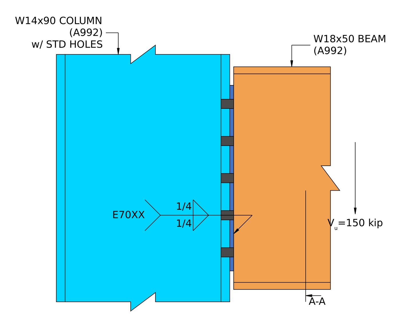
Elevação da conexão de exemplo. The end plate is welded to the beam web in the shop and bolted to the column flange in the field.
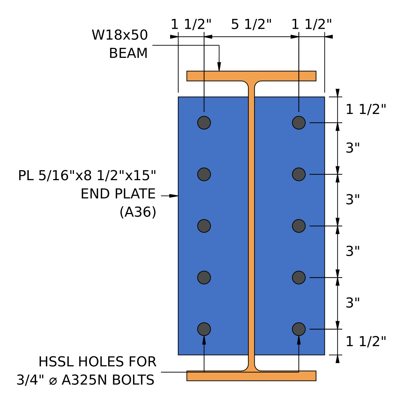
Seção A-A. Two columns of five bolts at a 5 1/2 em calibre, com 1 1/2 in edge distances all round the plate.
How do you design a shear end plate connection? As etapas em resumo
- Check the detailing limit at the beam side: the minimum plate depth.
- Check the fillet welds from the end plate to the beam web.
- Check the beam web in shear yielding.
- Verifique os limites de detalhamento no lado do apoio: espaçamento, edge distances and gage.
- Check the bolt group in shear.
- Check bolt bearing and tear-out on the end plate.
- Verifique o rolamento do parafuso e o rompimento do flange da coluna.
- Combinar cisalhamento, rolamento e arrancamento por parafuso para a resistência efetiva do grupo.
- Check block shear of the end plate.
- Check shear yielding and shear rupture of the end plate.
- Check end plate flexure using the double coped procedure.
- Check shear and moment interaction of the end plate.
Entradas de design para este exemplo
O código de projeto é AISC 360-16 LRFD. As propriedades da seção são do Manual AISC.
| Item | Símbolo | Valor |
|---|---|---|
| Cisalhamento vertical fatorado | [mathin] V_{u} [mathin] | 150 kip |
| Feixe | Momento da carga ao vivo, A992 | |
| Profundidade do feixe | [mathin] d_{bm} [mathin] | 18 no |
| Espessura da teia da viga | [mathin] t_{wb} [mathin] | 0.355 no |
| Largura do flange da viga / grossura | [mathin] b_{fb},\ t_{fb} [mathin] | 7.5 no / 0.57 no |
| Beam T dimension / kdet | [mathin] T_{bm},\ k_{det,bm} [mathin] | 15.5 no / 1.25 no |
| Área do feixe | [mathin] A_{bm} [mathin] | 14.7 em² |
| Rendimento do feixe / tensão de tração | [mathin] F_{yb},\ F_{ub} [mathin] | 50 ksi / 65 ksi |
| Coluna | W14x90, A992 | |
| Column depth / espessura da teia | [mathin] d_{sup},\ t_{ws} [mathin] | 14 no / 0.44 no |
| Column flange width / grossura | [mathin] b_{fs},\ t_{fs} [mathin] | 14.5 no / 0.71 no |
| Área da coluna | [mathin] A_{sup} [mathin] | 26.5 em² |
| Rendimento da coluna / tensão de tração | [mathin] F_{ys},\ F_{us} [mathin] | 50 ksi / 65 ksi |
| Módulo de elasticidade | [mathin] E [mathin] | 29000 ksi |
| Item | Símbolo | Valor |
|---|---|---|
| Placa final | PT 5/16 x 8 1/2 x 15, A36 | |
| End plate width / profundidade / grossura | [mathin] b_{p},\ d_{p},\ t_{p} [mathin] | 8.5 no / 15 no / 0.3125 no |
| End plate yield / tensão de tração | [mathin] F_{yp},\ F_{up} [mathin] | 36 ksi / 58 ksi |
| Bolts at the column | 3/4 em A325-N, cisalhamento simples | |
| Diâmetro do parafuso | [mathin] d_{b} [mathin] | 0.75 no |
| Tensão nominal do parafuso / tensão de cisalhamento | [mathin] F_{nt},\ F_{nv} [mathin] | 90 ksi / 54 ksi |
| Planos de cisalhamento | [mathin] N_{s} [mathin] | 1 |
| Holes in end plate / coluna | Horizontal com fenda curta (HSSL) / padrão (DST) | |
| Weld at the beam | 1/4 em filé, both sides of the web, E70XX | |
| Tamanho da solda / força de enchimento | [mathin] W,\ F_{EXX} [mathin] | 0.25 no / 70 ksi |
| Geometria | Símbolo | Valor |
|---|---|---|
| Linhas de parafusos / espaçamento entre linhas | [mathin] n_{r},\ s_{r} [mathin] | 5 / 3 no |
| Colunas de parafuso / calibrar | [mathin] n_{c},\ g_{s} [mathin] | 2 / 5.5 no |
| Total number of bolts | [mathin] N_{V} [mathin] | 10 |
| Vertical edge distance on end plate | [mathin] L_{ev} [mathin] | 1.5 no |
| Horizontal edge distance on end plate | [mathin] L_{eh} [mathin] | 1.5 no |
The plate dimensions add up from the drawing. The width is the two 1.5 in edge distances plus the 5.5 em calibre, 8.5 no. The depth is the two 1.5 in edge distances plus four 3 in spaces, 15 no.
Passo 1: Detailing limit at the beam side
The end plate has to be deep enough to brace the beam end against rotation about its own axis and to give the welds enough length. The minimum is half the beam’s T dimension, so for a W18x50 with T = 15.5 in it is 7.75 no.
| Limite de detalhamento | Limite (no) | Real (no) | DCR | Resultado |
|---|---|---|---|---|
| Profundidade mínima de conexão | 7.750 | 15.000 | 0.517 | cdot K_a |
[math] DCR = \frac{d}{c} = \frac{(7.75)}{(15)} = 0.51667 [math]
DCR = 0.517 < 1.0, OK
Passo 2: Fillet weld from the end plate to the beam web (AISC 360-16 J2.4)
The whole reaction passes from the beam web into the end plate through the two fillet welds, one on each face of the web. Their strength depends on size and length, and the base metal on either side of the weld can limit how much of the weld size counts.
Limite do metal base no tamanho da solda (Eq Manual AISC. 9-2)
This is the largest weld size, em décimos sextos de polegada, that the connected parts can support. Each weld line has the full end plate behind it, but the beam web carries a weld on both of its faces, so only half the web thickness is available to each weld. Com [mathin] t_{p} = 0.3125\,in [mathin], [mathin] F_{up} = 58\,ksi [mathin], [mathin] t_{wb} = 0.355\,in [mathin] e [mathin] F_{ub} = 65\,ksi [mathin]:
[math] D_{max} = \frac{t_{p} F_{up} \le \frac{t_{wb}}{2} F_{ub}}{3.09\,kip/in \times F_{EXX}/F_{E70XX}} [math]
[math] D_{max} = \frac{(0.3125\,in) \times (58\,ksi) \le (0.1775\,in) \times (65\,ksi)}{(3.09\,kip/in) \times (1)} [math]
[math] D_{max} = 3.7338 [math]
The beam web side gives the smaller value, so only 3.7338/16 no, sobre 0.233 no, do 1/4 in weld can be counted.
Effective weld length
The weld can only run along the flat part of the web, so its length is the least of the plate depth, the beam’s T dimension, and the beam depth less the cope or kdet zone at the top and bottom. There is no cope, so the kdet of 1.25 in applies at each end. Each of the two weld lines is then reduced by 2W for the end returns. Com [mathin] W = 0.25\,in [mathin], [mathin] d_{p} = 15\,in [mathin], [mathin] T_{bm} = 15.5\,in [mathin], [mathin] d_{bm} = 18\,in [mathin] e [mathin] k_{det,bm} = 1.25\,in [mathin]:
[math] L_{w} = 2 \left[ \min\left( d_{p},\, T_{bm},\, d_{bm} – \max\left(D_{ct}, k_{det,bm}\right) – \max\left(D_{cb}, k_{det,bm}\right) \right) – 2W \right] [math]
[math] L_{w} = 2 \times \left[ \min\left( (15\,in),\, (15.5\,in),\, (18\,in) – \max\left((0\,in), (1.25\,in)\right) – \max\left((0\,in), (1.25\,in)\right) \right) – 2 \times (0.25\,in) \right] [math]
[math] L_{w} = 29\,in [math]
Força de soldagem
A carga corre paralelamente às soldas, então [mathin] \theta = 0 [mathin] e não há aumento direcional. Com [mathin] F_{EXX} = 70\,ksi [mathin] e [mathin] \phi = 0.75 [mathin]:
[math] \phi R_{n} = \phi\, 0.6\, F_{EXX} \frac{\sqrt{2}}{2} \left( W \le \frac{D_{max}}{16} \right) \left[ 1 + 0.5 \left( \sin\theta \right)^{1.5} \right] L_{w} [math]
[math] \phi R_{n} = (0.75) \times 0.6 \times (70\,ksi) \times \frac{\sqrt{2}}{2} \times \left( (0.25\,in) \le \frac{(3.7338)}{(16)} \right) \times \left[ 1 + 0.5 \times (\sin(0))^{1.5} \right] \times (29\,in) [math]
[math] \phi R_{n} = 150.74\,kip [math]
DCR = 150 kip / 150.74 kip = 0.995 < 1.0, OK
This is the governing check. The weld is only just enough, and making it bigger would not help, because the 0.355 in beam web already limits the usable size to 0.233 no.
Passo 3: Beam web in shear yielding (AISC 360-16 J4.2)
The reaction travels along the beam web into the welds, so the web itself has to carry the full shear without yielding. The beam is not coped, so the full depth of the beam acts.
[math] A_{gv} = d_{bm}\, t_{wb} = (18\,in) \times (0.355\,in) = 6.39\,in^{2} [math]
Com [mathin] F_{yb} = 50\,ksi [mathin] e [mathin] \phi = 1 [mathin]:
[math] \phi R_{n,sy} = \phi\, 0.6\, F_{yb} A_{gv} = (1) \times 0.6 \times (50\,ksi) \times (6.39\,in^{2}) = 191.7\,kip [math]
DCR = 150 kip / 191.7 kip = 0.782 < 1.0, OK
Passo 4: Detalhando limites no lado do suporte (AISC 360-16 J3.3, J3.4, J3.5)
The bolt layout has to be buildable and match the assumptions behind the strength equations. Parafusos muito próximos rasgam entre os furos, bordas muito próximas rasgam, and the gage has to leave room for the beam web, the welds and the bolt heads.
Para 3/4 no parafuso o espaçamento mínimo é [mathin] 2\tfrac{2}{3} d_{b} = 2\,in [mathin] (J3.3) e a distância mínima da borda é 1 no (Tabela J3.4). The end plate has horizontal short slots, and its horizontal edge distance is measured from the end of the slot, então o incremento da Tabela J3.5 de 1/8 in raises its minimum to 1.125 no. On the column flange, the horizontal edge distance is what is left of the flange outside the bolts, [mathin] (b_{fs} – g_{s})/2 = (14.5 – 5.5)/2 = 4.5\,in [mathin].
| Limite de detalhamento | Limite (no) | Real (no) | DCR | Resultado |
|---|---|---|---|---|
| Espaçamento mínimo entre linhas de parafusos | 2.000 | 3.000 | 0.667 | cdot K_a |
| Espaçamento máximo entre linhas de parafusos | 6.000 | 3.000 | 0.500 | cdot K_a |
| Distância mínima da borda vertical da placa | 1.000 | 1.500 | 0.667 | cdot K_a |
| Distância mínima da borda horizontal da placa | 1.125 | 1.500 | 0.750 | cdot K_a |
| Support minimum horizontal edge distance | 1.000 | 4.500 | 0.222 | cdot K_a |
| Minimum bolt gage at support | 4.375 | 5.500 | 0.795 | cdot K_a |
| Minimum bolt gage at end plate | 2.355 | 5.500 | 0.428 | cdot K_a |
Para um limite mínimo, a relação é o limite sobre o real, e no máximo é real acima do limite. The governing row is the minimum bolt gage at the support:
[math] DCR = \frac{d}{c} = \frac{(4.375)}{(5.5)} = 0.79545 [math]
DCR = 0.795 < 1.0, OK
Passo 5: Bolt group shear at the support side (AISC 360-16 J3.6)
The bolts sit at the face of the column, in line with the reaction, and the two bolt columns are symmetric about the beam web. So the bolt group carries pure shear with no eccentricity, and every bolt takes an equal share.
Onde [mathin] \phi = 0.75 [mathin], [mathin] F_{nv} = 54\,ksi [mathin], [mathin] d_{b} = 0.75\,in [mathin], [mathin] N_{s} = 1 [mathin], [mathin] N_{V} = 10 [mathin] e [mathin] h_{f} = 1 [mathin] porque não há enchimentos (J5.2(uma)):
[math] \phi R_{n} = \phi\, F_{nv}\, \frac{\pi}{4} \left( d_{b} \right)^{2} N_{s}\, N_{V}\, h_{f} [math]
[math] \phi R_{n} = (0.75) \times (54\,ksi) \times \frac{\pi}{4} \times \left( (0.75\,in) \right)^{2} \times (1) \times (10) \times (1) [math]
[math] \phi R_{n} = 178.92\,kip [math]
DCR = 150 kip / 178.92 kip = 0.838 < 1.0, OK
Passo 6: Bolt bearing and tear-out on the end plate (AISC 360-16 J3.10)
Each bolt bears on the edge of its hole in the end plate. A placa se deforma no furo (consequência, limitado em 2.4 d t Fu) or tears a strip out to the next hole or to the plate’s end (arrancar, 1.2 lc t Fu). The bolt nearest the end of the plate has the shortest clear distance, então é o fraco.
The slots run horizontally and the load is vertical, so the hole dimension across the member length is the standard [mathin] d_{h} = 0.8125\,in [mathin]. Distância livre para o parafuso de borda, com [mathin] L_{ev} = 1.5\,in [mathin]:
[math] l_{c1} = L_{ev} – \frac{d_{h}}{2} = (1.5\,in) – \frac{(0.8125\,in)}{2} = 1.0938\,in [math]
Distância livre entre os parafusos, com [mathin] s_{r} = 3\,in [mathin]:
[math] l_{c2} = s_{r} – d_{h} = (3\,in) – (0.8125\,in) = 2.1875\,in [math]
Onde [mathin] t_{p} = 0.3125\,in [mathin], [mathin] F_{up} = 58\,ksi [mathin], [mathin] N_{V} = 10 [mathin], [mathin] n_{r} = 5 [mathin] e [mathin] \phi = 0.75 [mathin]. The bracket is the strength of one line of five bolts, and the factor N_V / n_r = 2 counts both lines:
[math] \phi R_{n,tearout} = \phi \left[ \min\left(1.2\, l_{c1},\, 2.4\, d_{b}\right) t_{p} F_{up} + \min\left(1.2\, l_{c2},\, 2.4\, d_{b}\right) t_{p} F_{up} \left( n_{r} – 1 \right) \right] \left( \frac{N_{V}}{n_{r}} \right) [math]
[math] \phi R_{n,tearout} = (0.75) \times \left[ \min\left(1.2 \times (1.0938\,in),\, 2.4 \times (0.75\,in)\right) \times (0.3125\,in) \times (58\,ksi) + \min\left(1.2 \times (2.1875\,in),\, 2.4 \times (0.75\,in)\right) \times (0.3125\,in) \times (58\,ksi) \times \left( (5) – 1 \right) \right] \times \left( \frac{(10)}{(5)} \right) [math]
[math] \phi R_{n,tearout} = 231.43\,kip [math]
DCR = 150 kip / 231.43 kip = 0.648 < 1.0, OK
O rasgo controla o parafuso da borda, porque 1.2 lc1 é menor que 2.4 banco de dados. The inner bolts are capped by bearing.
Passo 7: Rolamento do parafuso e desmontagem no flange da coluna (AISC 360-16 J3.10)
The same check applies to the column flange. The bolts are in the middle of a tall column, with no edge above or below them, so every bolt bears like an inner bolt.
[math] l_{c2} = s_{r} – d_{h} = (3\,in) – (0.8125\,in) = 2.1875\,in [math]
Onde [mathin] t_{fs} = 0.71\,in [mathin], [mathin] F_{us} = 65\,ksi [mathin] e [mathin] N_{V} = 10 [mathin]:
[math] \phi R_{n,tearout} = \phi\, \min\left(1.2\, l_{c2},\, 2.4\, d_{b}\right) t_{fs} F_{us}\, N_{V} [math]
[math] \phi R_{n,tearout} = (0.75) \times \min\left(1.2 \times (2.1875\,in),\, 2.4 \times (0.75\,in)\right) \times (0.71\,in) \times (65\,ksi) \times (10) [math]
[math] \phi R_{n,tearout} = 623.03\,kip [math]
DCR = 150 kip / 623.03 kip = 0.241 < 1.0, OK
A 0.71 in column flange is more than twice as thick as the end plate, so bearing on the column is rarely a concern with a thin shear end plate.
Passo 8: Resistência efetiva do grupo de parafusos (AISC 360-16 Comentário J3.6)
Cisalhamento de parafuso, rolamento e arrancamento não são verificações separadas. Cada parafuso carrega o mínimo de sua resistência ao cisalhamento e sua resistência ao rolamento ou ao rasgo em cada camada pela qual passa, e a força do grupo é a soma desses valores por parafuso.
Resistência de um parafuso em cisalhamento simples:
[math] \phi r_{v} = \frac{\phi R_{n}}{N_{V}} = \frac{(178.92\,kip)}{(10)} = 17.892\,kip [math]
Bearing and tear-out of one bolt on the end plate, for the edge bolt and an inner bolt:
[math] \phi r_{n1e} = \phi\, \min\left(1.2\, l_{c1},\, 2.4\, d_{b}\right) t_{p} F_{up} = (0.75) \times \min\left(1.2 \times (1.0938\,in),\, 2.4 \times (0.75\,in)\right) \times (0.3125\,in) \times (58\,ksi) = 17.842\,kip [math]
[math] \phi r_{n1i} = \phi\, \min\left(1.2\, l_{c2},\, 2.4\, d_{b}\right) t_{p} F_{up} = (0.75) \times \min\left(1.2 \times (2.1875\,in),\, 2.4 \times (0.75\,in)\right) \times (0.3125\,in) \times (58\,ksi) = 24.469\,kip [math]
Bearing of one bolt on the column flange:
[math] \phi r_{n2} = \phi\, \min\left(1.2\, l_{c2},\, 2.4\, d_{b}\right) t_{fs} F_{us} = (0.75) \times \min\left(1.2 \times (2.1875\,in),\, 2.4 \times (0.75\,in)\right) \times (0.71\,in) \times (65\,ksi) = 62.303\,kip [math]
Bolts are numbered from the top of each line, and the report takes bolt 5 as the edge bolt. The top and bottom edge distances are both 1.5 no, so the edge bolt has the same 1.0938 in clear distance whichever end it is at:
[math] \phi r_{eff,1} = \min\left( \phi r_{v},\, \phi r_{n1i},\, \phi r_{n2} \right) = \min\left( (17.892\,kip),\, (24.469\,kip),\, (62.303\,kip) \right) = 17.892\,kip [math]
[math] \phi r_{eff,2} = \min\left( \phi r_{v},\, \phi r_{n1e},\, \phi r_{n2} \right) = \min\left( (17.892\,kip),\, (17.842\,kip),\, (62.303\,kip) \right) = 17.842\,kip [math]
| Parafuso | Cisalhamento de parafuso (kip) | Consequência / arrancar, placa final (kip) | Consequência / arrancar, flange da coluna (kip) | Força efetiva (kip) |
|---|---|---|---|---|
| 1 | 17.89 | 24.47 | 62.30 | 17.89 |
| 2 | 17.89 | 24.47 | 62.30 | 17.89 |
| 3 | 17.89 | 24.47 | 62.30 | 17.89 |
| 4 | 17.89 | 24.47 | 62.30 | 17.89 |
| 5 | 17.89 | 17.84 | 62.30 | 17.84 |
Sum over one line, com [mathin] n_{1} = 4 [mathin] bolts at the inner value and [mathin] n_{2} = 1 [mathin] at the edge value:
[math] \sum \phi r_{eff} = n_{1}\, \phi r_{eff,1} + n_{2}\, \phi r_{eff,2} = (4) \times (17.892\,kip) + (1) \times (17.842\,kip) = 89.411\,kip [math]
[math] \phi R_{n,eff} = \left( \frac{N_{V}}{n_{r}} \right) \sum \phi r_{eff} = \left( \frac{(10)}{(5)} \right) \times (89.411\,kip) = 178.82\,kip [math]
DCR = 150 kip / 178.82 kip = 0.839 < 1.0, OK
Bolt shear governs four bolts in each line, and tear-out on the 5/16 in plate governs the edge bolt by 0.05 kip. That is why the effective strength comes out a fraction below the bolt shear strength in Step 5. Você pode executar a mesma conexão no calculadora de design de conexão gratuita and try a larger edge distance to see the two values meet.
Passo 9: Block shear of the end plate (AISC 360-16 J4.3)
A block of the end plate can tear out on each side of the beam web: shear along the bolt line to the end of the plate, plus tension across to the plate’s outer edge. That makes two L-shaped blocks, one per bolt column, so the areas below use [mathin] 2t_{p} = 0.625\,in [mathin] and count one bolt column on each side.
Área líquida em tensão. O plano de tensão corre horizontalmente, ao longo das ranhuras, então ele usa o comprimento do slot [mathin] d_{h} = 1\,in [mathin], com [mathin] n_{c} = 2 [mathin], [mathin] s_{c} = 0\,in [mathin] e [mathin] L_{eh} = 1.5\,in [mathin]. Cada buraco adiciona 1/16 em caso de danos durante o soco (B4.3):
[math] A_{nt} = 2t_{p} \left[ \left( \frac{n_{c}}{2} – 1 \right) s_{c} + L_{eh} – \left( \frac{n_{c}}{2} – 0.5 \right) \left( d_{h} + 0.0625\,in \right) \right] [math]
[math] A_{nt} = (0.625\,in) \times \left[ ((1)-1) \times (0\,in) + (1.5\,in) – ((1) – 0.5) \times ((1\,in) + (0.0625\,in)) \right] = 0.60547\,in^{2} [math]
Áreas bruta e líquida em cisalhamento. O plano de cisalhamento corre verticalmente, através dos slots, so the net area uses [mathin] d_{h} = 0.8125\,in [mathin]:
[math] A_{gv} = 2t_{p} \left[ L_{ev} + (n_{r}-1)\, s_{r} \right] = (0.625\,in) \times \left[ (1.5\,in) + ((5)-1) \times (3\,in) \right] = 8.4375\,in^{2} [math]
[math] A_{nv} = 2t_{p} \left[ d_{p} – L_{ev} – (n_{r} – 0.5)\left( d_{h} + 0.0625\,in \right) \right] [math]
[math] A_{nv} = (0.625\,in) \times \left[ (15\,in) – (1.5\,in) – ((5) – 0.5) \times ((0.8125\,in) + (0.0625\,in)) \right] = 5.9766\,in^{2} [math]
Resistência ao cisalhamento do bloco, com [mathin] U_{bs} = 1 [mathin] because each block has a single bolt column and the tension is uniform, [mathin] F_{up} = 58\,ksi [mathin], [mathin] F_{yp} = 36\,ksi [mathin] e [mathin] \phi = 0.75 [mathin]:
[math] \phi R_{n} = \phi \left( 0.6\, F_{up} A_{nv} + U_{bs} F_{up} A_{nt} \le 0.6\, F_{yp} A_{gv} + U_{bs} F_{up} A_{nt} \right) [math]
[math] \phi R_{n} = (0.75) \times \left( 0.6 \times (58\,ksi) \times (5.9766\,in^{2}) + (1) \times (58\,ksi) \times (0.60547\,in^{2}) \le 0.6 \times (36\,ksi) \times (8.4375\,in^{2}) + (1) \times (58\,ksi) \times (0.60547\,in^{2}) \right) [math]
[math] \phi R_{n} = 163.03\,kip [math]
DCR = 150 kip / 163.03 kip = 0.920 < 1.0, OK
O lado de cisalhamento da equação governa. A36 tem uma baixa relação rendimento/tração, então o plano de cisalhamento bruto cede antes que o plano de cisalhamento líquido se rompa. This is the second highest ratio in the connection.
Passo 10: Shear yielding and shear rupture of the end plate (AISC 360-16 J4.2)
The full reaction passes down through the end plate as vertical shear on two planes, um de cada lado da alma da viga. A seção bruta não deve ceder, e a seção da rede através dos furos dos parafusos não deve romper.
Cessamento ao cisalhamento (Eq. J4-3)
Com [mathin] n_{sp} = 2 [mathin] planos de cisalhamento:
[math] A_{gv} = d_{p}\, n_{sp}\, t_{p} = (15\,in) \times (0.625\,in) = 9.375\,in^{2} [math]
[math] \phi R_{n,sy} = \phi\, 0.6\, F_{yp} A_{gv} = (1) \times 0.6 \times (36\,ksi) \times (9.375\,in^{2}) = 202.5\,kip [math]
Ruptura por cisalhamento (Eq. J4-4)
[math] A_{nv} = n_{sp}\, t_{p} \left[ d_{p} – n_{r}\left( d_{h} + 0.0625\,in \right) \right] = (0.625\,in) \times \left[ (15\,in) – (5) \times ((0.8125\,in) + (0.0625\,in)) \right] = 6.6406\,in^{2} [math]
[math] \phi R_{n,sr} = \phi\, 0.6\, F_{up} A_{nv} = (0.75) \times 0.6 \times (58\,ksi) \times (6.6406\,in^{2}) = 173.32\,kip [math]
[math] \phi R_{n} = \min\left( \phi R_{n,sy},\, \phi R_{n,sr} \right) = \min\left( (202.5\,kip),\, (173.32\,kip) \right) = 173.32\,kip [math]
DCR = 150 kip / 173.32 kip = 0.865 < 1.0, OK
Passo 11: End plate flexure using the double coped procedure (AISC 360-16 F11.2)
The bolts are 2 3/4 in out from the web on each side, so each half of the end plate bends as a short cantilever from the web to its bolt line. A thin plate can buckle sideways before it yields. O Manual AISC trata disso com o procedimento para uma viga fixada em ambos os banzos, treating each half of the plate like a beam web with the flanges cut away. The unbraced length is the distance from the face of the web to the bolt line, [mathin] L_{b} = (g_{s} – t_{wb})/2 = (5.5 – 0.355)/2 = 2.5725\,in [mathin].
Verificação de alcance
Onde [mathin] E = 29000\,ksi [mathin], [mathin] F_{yp} = 36\,ksi [mathin], [mathin] d_{p} = 15\,in [mathin] e [mathin] t_{p} = 0.3125\,in [mathin]:
[math] \frac{L_{b} d}{t^{2}} = \frac{(2.5725\,in) \times (15\,in)}{(0.3125\,in)^{2}} = 395.14 [math]
[math] \frac{0.08 E}{F_{y}} = \frac{0.08 \times (29000\,ksi)}{(36\,ksi)} = 64.444 \qquad \frac{1.9 E}{F_{y}} = \frac{1.9 \times (29000\,ksi)}{(36\,ksi)} = 1530.6 [math]
Então [mathin] \frac{0.08E}{F_{y}} \lt \frac{L_{b} d}{t^{2}} \le \frac{1.9E}{F_{y}} [mathin], Estimativa da capacidade da pilha. F11-2 se aplica.
Section moduli of the end plate
[math] Z = \frac{t_{p} \left( d_{p} \right)^{2}}{4} = \frac{(0.3125\,in) \times ((15\,in))^{2}}{4} = 17.578\,in^{3} [math]
[math] S = \frac{t_{p} \left( d_{p} \right)^{2}}{6} = \frac{(0.3125\,in) \times ((15\,in))^{2}}{6} = 11.719\,in^{3} [math]
Fator de modificação da flambagem lateral-torcional (Eq Manual AISC. 9-15)
The cope depth is taken as zero, [mathin] d_{ct} = 0\,in [mathin]:
[math] C_{b} = \left[ 3 + \ln\left( \frac{L_{b}}{d_{p}} \right) \right] \left( 1 – \frac{d_{ct}}{d_{p}} \right) \ge 1.84 [math]
[math] C_{b} = \left[ 3 + \ln\left( \frac{(2.5725\,in)}{(15\,in)} \right) \right] \times \left( 1 – \frac{(0\,in)}{(15\,in)} \right) \ge 1.84 [math]
[math] C_{b} = 1.84 [math]
Resistência à flexão
Com [mathin] \phi = 0.9 [mathin], and a factor of 2 for the two halves of the plate:
[math] \phi M_{n} = \phi \left[ C_{b} \left[ 1.52 – 0.274 \left( \frac{L_{b} d}{t^{2}} \right) \left( \frac{F_{yp}}{E} \right) \right] F_{yp} S \le F_{yp} Z \right] 2 [math]
[math] \phi M_{n} = (0.9) \times \left[ (1.84) \times \left[ 1.52 – 0.274 \times ((395.14)) \times \left( \frac{(36\,ksi)}{(29000\,ksi)} \right) \right] \times (36\,ksi) \times (11.719\,in^{3}) \le (36\,ksi) \times (17.578\,in^{3}) \right] \times 2 [math]
[math] \phi M_{n} = 94.922\,kip\text{-}ft \;(1139.1\,kip\text{-}in) [math]
A tampa de momento de plástico [mathin] F_{yp} Z [mathin] governa, so buckling does not reduce the strength over this short length.
Capacidade de cisalhamento equivalente
[math] \phi V_{n} = \frac{\phi M_{n}}{L_{b}} = \frac{(94.922\,kip\text{-}ft)}{(2.5725\,in)} = 442.78\,kip [math]
DCR = 150 kip / 442.78 kip = 0.339 < 1.0, OK
Passo 12: Shear and moment interaction of the end plate (Eq Manual AISC. 10-5)
The end plate carries shear and bending at the same section at the same time, então os dois têm que ser verificados juntos. O Manual usa uma interação circular entre a resistência ao cisalhamento e a resistência à flexão.
The moment in the plate is the reaction times the unbraced length, com [mathin] V_{r} = 150\,kip [mathin] e [mathin] L_{b} = 2.5725\,in [mathin]:
[math] M_{r} = V_{r}\, L_{b} = (150\,kip) \times (2.5725\,in) = 32.156\,kip\text{-}ft [math]
Com [mathin] \phi V_{n} = 202.5\,kip [mathin] do escoamento por cisalhamento na Etapa 10 e [mathin] \phi M_{n} = 94.922\,kip\text{-}ft [mathin] da etapa 11:
[math] I_{nt} = \left( \frac{V_{r}}{\phi V_{n}} \right)^{2} + \left( \frac{M_{r}}{\phi M_{n}} \right)^{2} [math]
[math] I_{nt} = \left( \frac{(150\,kip)}{(202.5\,kip)} \right)^{2} + \left( \frac{(32.156\,kip\text{-}ft)}{(94.922\,kip\text{-}ft)} \right)^{2} = 0.66346 [math]
DCR = 0.66346 / 1.0 = 0.663 < 1.0, OK
The short lever arm keeps the moment small, so most of the interaction comes from shear.
Summary of the shear end plate connection design checks
| Verificação de projeto | Demanda | Capacidade | DCR | Resultado |
|---|---|---|---|---|
| Limites de detalhamento no lado da viga | 7.750 no | 15.000 no | 0.517 | cdot K_a |
| Weld at beam side | 150.000 kip | 150.739 kip | 0.995 | cdot K_a |
| Beam web in shear | 150.000 kip | 191.700 kip | 0.782 | cdot K_a |
| Detalhando limites no lado do suporte | 4.375 no | 5.500 no | 0.795 | cdot K_a |
| Cisalhamento de grupo de parafusos | 150.000 kip | 178.924 kip | 0.838 | cdot K_a |
| Rolamento de parafuso e remoção, placa final | 150.000 kip | 231.434 kip | 0.648 | cdot K_a |
| Rolamento de parafuso e remoção, flange da coluna | 150.000 kip | 623.025 kip | 0.241 | cdot K_a |
| Resistência efetiva do grupo de parafusos | 150.000 kip | 178.822 kip | 0.839 | cdot K_a |
| Block shear of end plate | 150.000 kip | 163.025 kip | 0.920 | cdot K_a |
| Shear yielding and rupture of end plate | 150.000 kip | 173.320 kip | 0.865 | cdot K_a |
| End plate flexure (procedimento duplo enfrentado) | 150.000 kip | 442.784 kip | 0.339 | cdot K_a |
| Shear and moment interaction of end plate | 0.663 | 1.000 | 0.663 | cdot K_a |
A conexão passa em todas as verificações. The weld at the beam side governs at 0.995, because the 0.355 in beam web limits the usable weld size to about 0.233 no. Block shear of the end plate is next at 0.920, then shear rupture of the end plate at 0.865. Plate flexure is far from critical at 0.339, which is typical for a shear end plate: the bolts sit close to the web, so the lever arm is short.
O que mudar se uma verificação falhar
- Weld at the beam side: a longer weld helps, so use a deeper end plate, up to the beam’s T dimension. A bigger fillet adds nothing once the beam web base metal limit governs. A beam with a thicker web raises that limit.
- Beam web shear: pick a beam with a thicker or deeper web. The end plate cannot help this check.
- Bolt shear or effective strength: adicione uma linha de parafusos ou use um parafuso maior. A325-X (tópicos excluídos) ou parafusos A490 aumentam a tensão de cisalhamento.
- Tear-out on the end plate: increase the vertical edge distance, ou use uma placa mais grossa.
- Cisalhamento de bloco, shear yielding or shear rupture of the end plate: use a thicker or deeper plate. A longer horizontal edge distance also adds to the block shear tension area.
- Plate flexure or interaction: reduce the gage so L_b is shorter, ou use uma placa mais grossa. Keep the plate thin enough to stay flexible, because a stiff end plate starts to act like a moment connection.
- Gage or edge distance at the support: adjust the gage within the column flange width. The gage has to clear the beam web and its welds on the plate side and suit the column flange on the support side.
Perguntas frequentes
What is the difference between a shear end plate and a moment end plate?
A shear end plate is welded to the beam web only, is thin (5/16 in here), and is designed to flex so the beam end can rotate. A moment end plate, flush or extended, is also welded to the beam flanges, is much thicker, and uses its bolts in tension to resist the beam’s end moment. This example only carries vertical shear, so it is a simple connection.
Why is there no bolt group eccentricity in this example?
The bolts sit at the face of the column, on the line where the reaction is delivered, and the two bolt columns are placed symmetrically on either side of the beam web. So the bolt group carries pure shear and every bolt takes the same share. The bolt group strength is simply the strength of one bolt times the ten bolts.
Why does the beam web, not the end plate, limit the weld?
Eq Manual AISC. 9-2 limits the weld size to what the base metal next to it can carry. The beam web has a fillet weld on both of its faces, so each weld is backed by only half the 0.355 in web. Each weld line has the full 5/16 in end plate behind it. The web gives the smaller value, 3.7338 sixteenths, or about 0.233 no, which is less than the 1/4 in weld that was specified.
Why does the end plate have short-slotted holes?
Horizontal short slots in the end plate give the erector some fit-up tolerance across the beam, which helps when the column or the beam length is slightly off. Porque as ranhuras são horizontais e a carga é vertical, bearing and tear-out use the standard hole dimension across the slot. The slot length only appears in the block shear tension area and in the 1/8 in edge distance increment from Table J3.5.
How thick should a shear end plate be?
Thin enough to rotate. Peça Manual AISC 10 limits end plates in this kind of simple connection to 1/4 para dentro 3/8 em grosso, with a gage of 3 1/2 para dentro 5 1/2 no, so the plate can bend as the beam end rotates. A thicker plate or a narrower gage makes the connection stiffer and starts to pull moment into the column. This example uses a 5/16 in plate at a 5 1/2 em calibre.
Which check usually governs a shear end plate connection?
On a beam with a thin web, the weld to the beam web often governs, because the web base metal limits the weld size and the weld length is capped by the beam’s T dimension. On a thicker web the end plate itself, through block shear or shear rupture, usually takes over. In this example the weld governs at 0.995, with block shear of the end plate next at 0.920.
Este exemplo segue a 15ª edição do AISC ou o Manual da 16ª edição do AISC?
Segue AISC 360-16 e o Manual AISC 15ª Edição, que está escrito em torno dessa Especificação. O Manual AISC 16ª Edição combina com o posterior 360-22 Especificação. The limit states for a shear end plate connection are the same in both, mas as referências de cláusula e página se movem, então compare-os com a edição que seu projeto usa.
Como isso mudaria para AISC ASD em vez de LRFD?
Os estados limites e as resistências nominais são idênticos. Com AISC ASD você compara a reação de nível de serviço com a resistência nominal dividida por um fator de segurança em vez de multiplicar por um fator de resistência. Um fator de resistência de 0.75 torna-se um fator de segurança de 2.00, rendimento de cisalhamento 1.00 torna-se 1.50, e flexão 0.90 torna-se 1.67. As combinações de carga também mudam, então a demanda é menor.
Design a shear end plate connection for free
Cada número nesta página vem de uma solução. Pick the end plate configuration, entre no seu raio, coluna, placa, parafusos, weld and reaction, e veja cada uma dessas verificações em seu navegador. Não há nada para instalar.
O módulo SkyCiv Connection Design é o software de design de conexão por trás deste exemplo. Fornece o relatório de cálculo completo com todas as equações e seus números, como as etapas acima, além de todas as capacidades e DCR, para AISC 360-16 (LRFD e ASD) e a norma AS 4100:2020. A calculadora de parafuso e calculadora de solda cubra o grupo de parafusos e verifique a soldagem por conta própria.
Referências
- AISC 360-16, correspondente às especificações para aço estrutural: B3.4, B4.3, F11.2 (Eq. F11-2), J2.4 (Eq. J2-4), J3.3, J3.4 (Tabela J3.4), J3.5 (Tabela J3.5), J3.6 (Eq. J3-1) e Comentário, J3.10 (Eq. J3-6a, J3-6c), J4.2 (Eq. J4-3, J4-4), J4.3 (Eq. J4-5), J5.2(uma).
- Manual de construção em aço AISC, 15ª edição: Papel 9, Eq. 9-2 Estimativa da capacidade da pilha. 9-15 (página 9-9); Papel 10, weld length less 2w at the ends, Estimativa da capacidade da pilha. 10-5 (página 10-90).
- Dimensionamento de ligações metálicas utilizando AISC 360-16
- Parafusos e soldas no design de conexão SkyCiv

Harold Munalem
gerente de produto, Projeto de Conexão
10+ anos em projetos de conexões de aço
LinkedIn
