
A column splice joins one column to the one above it. Columns arrive in mill lengths, and a building taller than that length needs its columns spliced, usually a few feet above floor level where the erector can reach the joint from the deck. Splices also turn up in retrofit work, where a column is extended, replaced or reinforced after a change in loading.
The splice has to carry whatever the column carries across the joint: axial compression, axial tension where uplift or overturning governs, o cisalhamento, Os três tipos de forças internas que se espera que as conexões de aço transmitam incluem força axial. AISC 360-16 sets out the procedures for each. This page walks through designing one in SkyCiv Connection Design.
Os cálculos por trás das conexões de emenda de coluna
A column splice is a slow connection to calculate by hand. Each plate has to be checked in tension, compression and bearing, each bolt group in shear, and the whole joint for block shear, all of it doubled because the upper and lower columns are separate connections either side of the splice. AISC 360-16 gives the procedure for the axial, shear and moment capacity of each of those pieces.
A column splice calculator runs the same procedure. You supply the column sections, tamanhos de placa, bolt specifications and loads, and it returns every check with its utilization ratio and the clause it came from, so the arithmetic stops being the part of the job that takes the time.
Aparafusamento ou Soldagem: Escolhendo o método de conexão correto
Bolting is the usual choice for a column splice. A bolted splice is made in the air by an erector with a wrench, it tolerates the small misalignments that come with erecting a frame, and it can be slackened and adjusted if something does not line up. Welding a splice at height means preheat, position welding and inspection on a joint that is hard to reach.
Preparando a superfície de contato da coluna: A “Adequado para suportar” Abordagem
Where the column ends are prepared so the two sections sit in full contact, compression transfers through bearing rather than through the bolts. That usually means fewer bolts and thinner plates, because the plates only have to carry tension, cisalhamento e momento.
It is a decision that has to reach the fabricator. Fit to bear is a preparation requirement on the shop drawings, not something the connection design can assume on its own, so if you design on that basis, say so on the drawing.
A necessidade de conexões de emenda de coluna
Splices appear wherever a column cannot be a single piece: buildings taller than the available mill length, sections that would be impossible to ship or lift in one, and retrofits where a column is extended or strengthened. In each case the splice has to reproduce the continuity the column would have had without it.
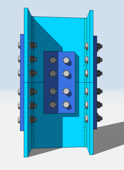
Designing a Column Splice in SkyCiv
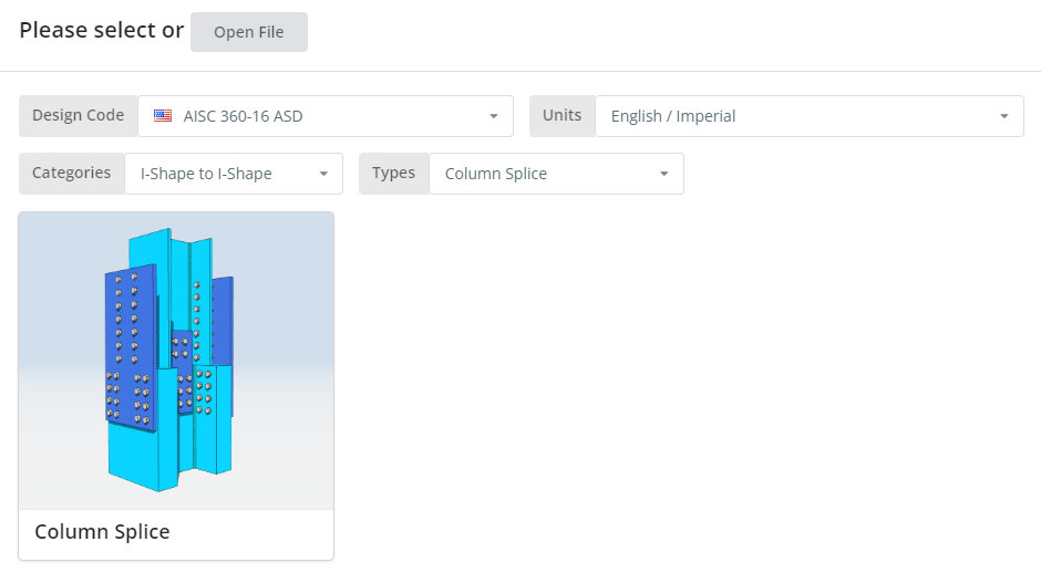
O código de projeto pode ser AISC 360-16 ASD ou LRFD, e unidades inglesas/imperiais ou SI/métricas. Clique no “Emenda de coluna” telha.
Guia Detalhes
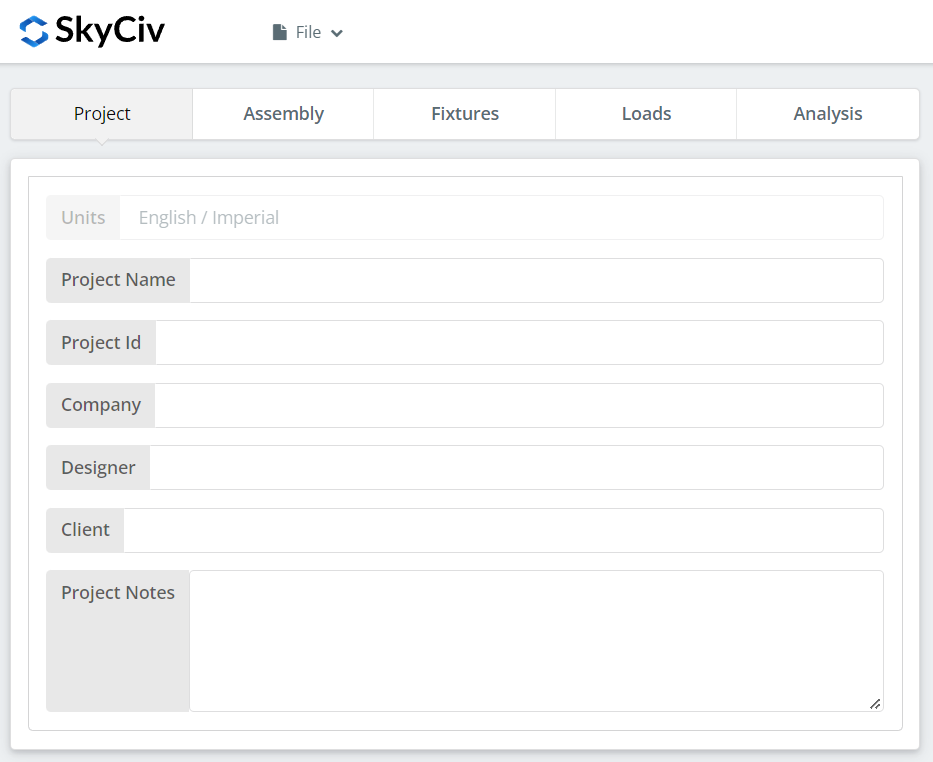
Registre aqui os detalhes do projeto. Nada disso altera os cálculos, mas isso traz para o relatório, which is what makes a set of designs traceable later.
Aba de montagem
Três guias ficam em Assembly: the Lower Column, the Upper Column, e a Conexão, which holds the flange plate and web plate.
Guia Coluna Inferior
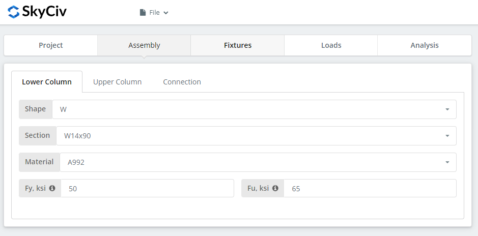
Specify the section and material grade of the lower column. A992 e A36 estão na lista; para qualquer outra coisa, escolha Personalizado e insira Fy e Fu.
Guia da coluna superior
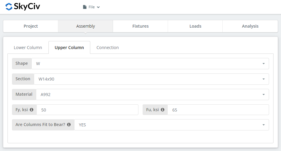
The same inputs, plus the option to declare the columns fit to bear. Selecione “SIM” and the compressive load is designed at the column contact surface instead of through the bolted connection, which gives a more economical connection. Como acima, that is a requirement you have to pass to the fabricator: the columns must actually be prepared to bear.
Aba Conexão: Placa de flange
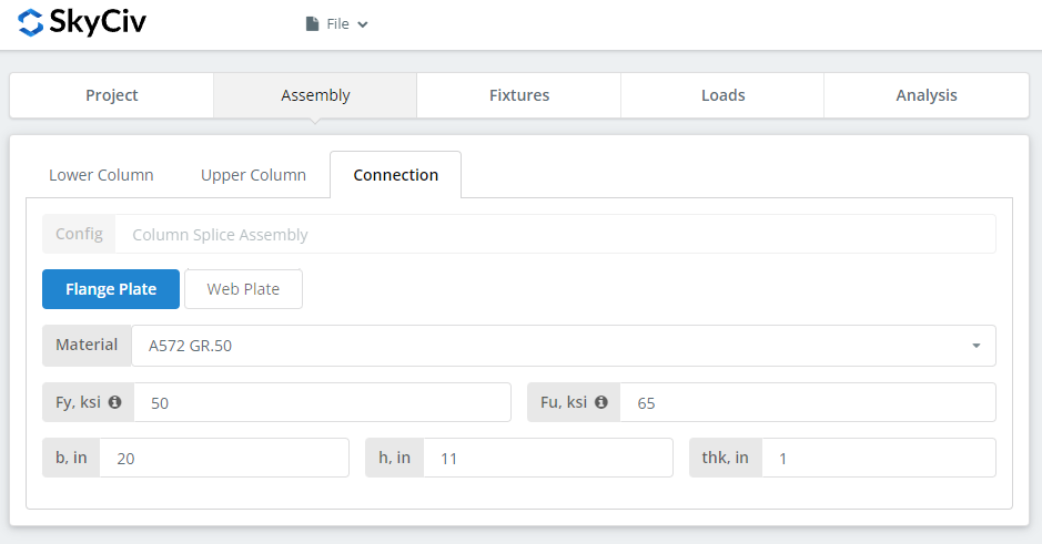
Definir as propriedades da placa de flange: grau A36, A992 ou A572 Gr.50, ou personalizado com seu próprio Fy e Fu, então b (largura), h (altura) e obrigado (grossura). Watch the 3D renderer as you type and check the plate geometry makes sense, in particular that there is room for the bolt group you are about to define on the Fixtures tab.
Aba Conexão: Momento da carga ao vivo
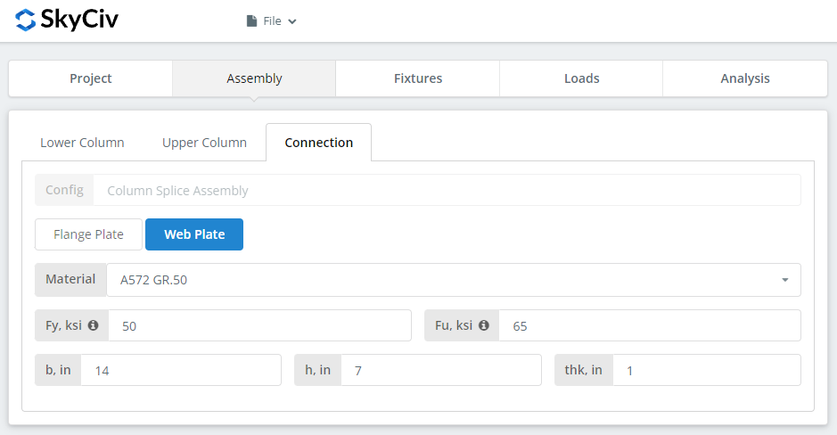
Same inputs as the flange plate. Verifique o renderizador novamente antes de prosseguir.
Luminária 1-4 Aba
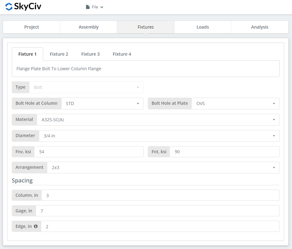
This is where the bolts are defined, one fixture per interface:
Luminária 1 – Placa de flange para flange inferior da coluna
Luminária 2 – Placa de flange para flange da coluna superior
Luminária 3 – Placa Web para Web da Coluna Inferior
Luminária 4 – Placa Web para Web da Coluna Superior
Primeiro, the bolt-hole types at the column flange or web and at the plates. Os fabricantes geralmente pedem furos padrão (DST) nos membros e furos superdimensionados (OVS) in the plate, que compra tolerância adequada no campo.
A continuação, o material ou classe do parafuso: A307, A325, A490 ou personalizado. A325 e A490 são classes dentro da ASTM F3125, que consolidou as especificações independentes mais antigas, so a drawing calling for A325 is calling for F3125 Grade A325. Escolha N ou X para uma conexão do tipo rolamento e SC para deslizamento crítico.
As juntas de deslizamento crítico têm menor capacidade de parafuso de projeto do que as do tipo rolamento, então use-os onde o deslizamento realmente importa: furos superdimensionados ou com fenda, reversão de carga, ou fadiga. Neste exemplo, using OVS holes in either the column or the plate means the bolts are automatically checked as slip-critical. Entre N e X, X fornece a maior capacidade de cisalhamento do parafuso, mas as roscas devem ser excluídas do plano de cisalhamento, which the erector has to know about. Entre SC(A) e SC(B), SC(B) oferece maior capacidade e requer uma superfície de contato mais cuidadosamente preparada, por exemplo, limpeza por jateamento comercial SSPC-SP6.
Então o diâmetro do parafuso, de 08/05″ para 1-1/2″ ou os equivalentes métricos, e o arranjo, até 8 fileiras de parafusos e 12 colunas de parafusos. Set the bolt row spacing, espaçamento de coluna e medidor. A “Beira” input is the distance from the column end to the first bolt column.
For more on the fastener side of this, veja a documentação em parafusos.
Guia de Cargas
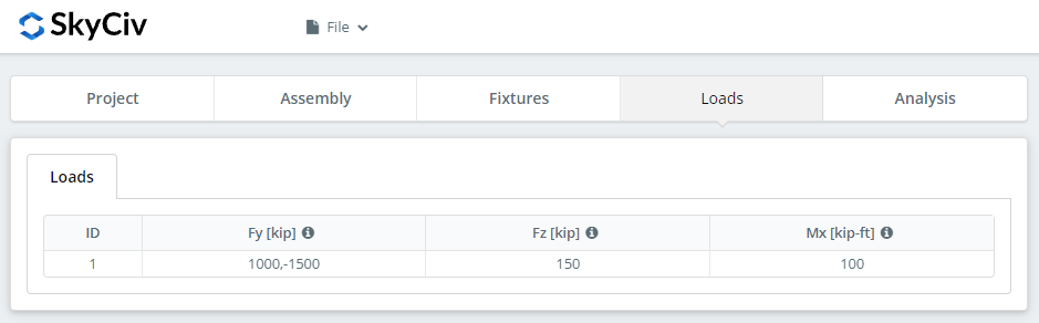
Enter the compressive or tensile load as ‘Fy’, the horizontal shear as ‘Fz’, and the strong axis moment as ‘Mx’. Hover the tooltips for the sign convention and direction of each.
Combine as cargas com o método de projeto que você escolheu no início. O LRFD leva cargas fatoradas em relação à resistência do projeto; ASD leva cargas de serviço contra a força permitida. O software não consegue dizer o que você digitou, so mixing them produces a utilization ratio that means nothing.
Guia Resultados
Clique “Executar verificações de design”. Qualquer coisa que esteja faltando nas guias anteriores é sinalizada aqui, em vez de ser padronizada silenciosamente.
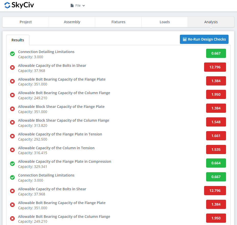
O resumo mostra se a conexão passou, with a utilization ratio against each check and the governing one called out. Se falhou, altere as entradas nas guias anteriores e clique em “Executar novamente verificações de design”. Quando isso passa, “Ver relatório de cálculo” abre o relatório detalhado.
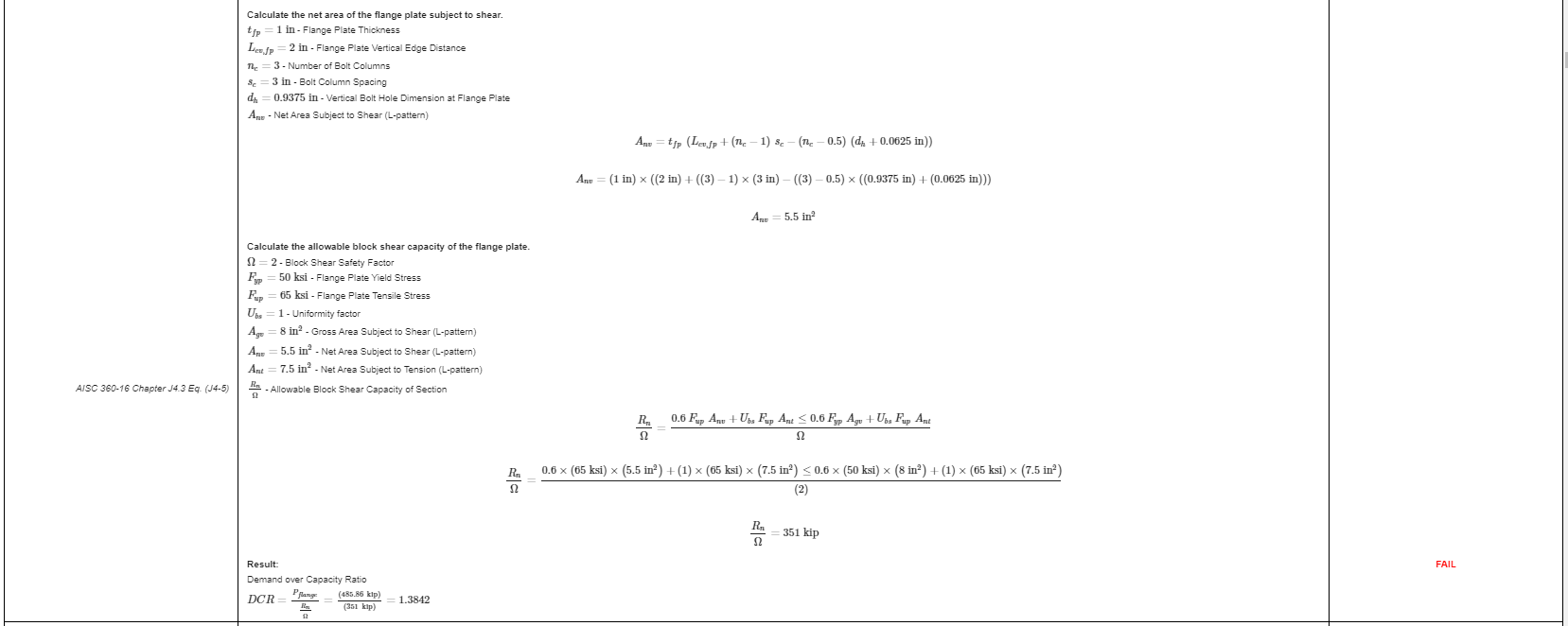
Isso é um extrato do relatório. Cada verificação traz sua referência ao manual ou especificação AISC, and the working is laid out the way the specification lays it out, so a reviewing engineer can follow it line by line instead of reverse-engineering a result.
Aquié uma cópia em PDF do relatório de cálculo completo e detalhado.
Designing a beam splice instead? A beam splice calculator works the same way.
Experimente você mesmo
The link below opens the module with the column splice already loaded. Enter your sections, pratos, parafusos e cargas, and every check and code reference is shown in full. Ele roda no navegador, sem nada para instalar.
