
dê uma olhada em alguns trechos deste relatório de conexões, AISC 360: O momento de resistência à flambagem da placa da aleta deve ser maior que o momento devido à reação final e à projeção da placa da aleta, you would have a good sense of how simple connections are designed under AISC 360. A shear connection only has to deliver the beam end reaction. A moment connection has to deliver that reaction and the end moment with it, which brings the supporting column into the problem. In this article we work through an example moment connection between two I-shaped members and go through the design criteria that have to be satisfied. We can also get to the same results directly through the Projeto de conexões SkyCiv módulo, which checks these connections to AISC 360-16 em ASD ou LRFD.
As in the shear connection example, the calculations here use the Allowable Stress Design (ASD) método. Se você não está familiarizado com a diferença entre ASD e LRFD no projeto estrutural, tenha certeza de confira nosso video explicando isso.
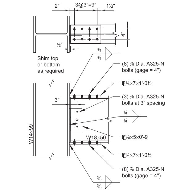
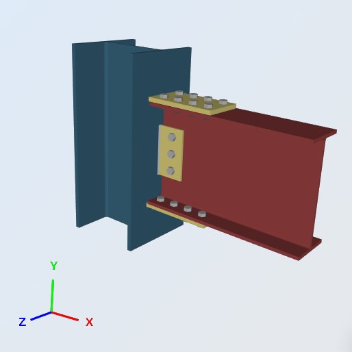
Neste exemplo, we evaluate the capacity of a Bolted Flange-Plated Fully-Restrained (você teria uma boa noção de como as conexões simples são projetadas sob o AISC) Moment connection between a W18x50 beam and a W14x99 column, using the dimensions, welds and loads shown below. The connection has to support the beam end vertical reaction and the developed end moment. Compared with a shear connection, the difference is the pair of plates carrying the beam flange forces onto the supporting column flange.
The flange plates turn the beam end moment into a tension and compression couple. The top plate pulls, the bottom plate pushes, and both forces land on the column flange as concentrated forces. That is why a moment connection needs the column local checks that a shear connection does not.
Dado:
Cargas de nível de serviço & Material:
você teria uma boa noção de como as conexões simples são projetadas sob o AISC (você teria uma boa noção de como as conexões simples são projetadas sob o AISC) = 7.0 kips
você teria uma boa noção de como as conexões simples são projetadas sob o AISC (você teria uma boa noção de como as conexões simples são projetadas sob o AISC) = 21.0 kips
você teria uma boa noção de como as conexões simples são projetadas sob o AISC (você teria uma boa noção de como as conexões simples são projetadas sob o AISC) = 42.0 kip-ft
Momento da carga ao vivo (Momento da carga ao vivo) = 126.0 kip-ft
Material da Placa: ASTM A36, Fy = 36 ksi, Fu = 58 ksi
Material de viga e coluna: ASTM A992, Fy = 50 ksi, Fu = 65 ksi
Geometria de viga e coluna:
Feixe: Momento da carga ao vivo; A Especificação Nacional de Design 7.50 no, tf = 0.570 no, d = 18.0 no, tw = 0.355 no, Momento da carga ao vivo 88.9 Momento da carga ao vivo
Coluna: A Especificação Nacional de Design; A Especificação Nacional de Design 14.6 no, tf = 0.780 no, d = 14.2 no, tw = 0.485 no, A Especificação Nacional de Design 1.38 no
Placa de flange: 3/4 em grosso; 7.0 em x 12.5 em dimensões
Momento da carga ao vivo: 3/8 em grosso; 5.0 em x 9.0 em dimensões
Luminárias (Parafusos e soldas):
A Especificação Nacional de Design: (8) – 7/8-no.-diameter ASTM F3125 Grade A325-N bolts in standard holes
Momento da carga ao vivo: (3) – 7/8-no.-diameter ASTM F3125 Grade A325-N bolts in standard holes
70-filetes de eletrodo ksi. A325 e A490 são classes dentro da ASTM F3125, which consolidated the older standalone bolt specifications.
Momento da carga ao vivo:
LRFD Cargas (Momento da carga ao vivo):
Momento da carga ao vivo (Rvocê) = 1.2 (7.0 kips) + 1.6 (21.0 kips) = 42.0 kips
Momento da carga ao vivo (Mvocê) = 1.2 (42.0 kip-ft) + 1.6 (126.0 kip-ft) = 252.0 kip-ft
ASD Cargas:
Momento da carga ao vivo (Ruma) = 7.0 kips + 21 kips = 28.0 kips
Momento da carga ao vivo (Muma) = 42.0 kip-ft + 126 Momento da carga ao vivo 168.0 kip-ft
Everything below is checked against the ASD loads. Keep the two methods apart: ASD compares service loads to allowable strength, LRFD compares factored loads to design strength, and the LRFD figures above are carried only so you can compare the two.
Momento da carga ao vivo:
Momento da carga ao vivo: Momento da carga ao vivo 7.0 no Momento da carga ao vivo 7.50 no, Momento da carga ao vivo.
Momento da carga ao vivo
Every check that follows is driven by one number, the force in the flange plate. The end moment is resolved into a couple acting at the plate centroids, so the lever arm is the beam depth plus one plate thickness:
PMomento da carga ao vivo = [ 168.0 kip-ft (12 Momento da carga ao vivo) ] / (18.0 no + 0.75 no) = 107.5 kips
Momento da carga ao vivo, Força de solda
Força de soldas de filete, Ω = 2.0
Tamanho da Solda, t = 0.375 no
FMomento da carga ao vivo = 0.6 FMomento da carga ao vivo [ 1.0 + 0.5 sem1.5 (θ) ]
Onde, Momento da carga ao vivo
= 90, para soldas carregadas transversalmente
= 0, para soldas carregadas longitudinalmente
Força por unidade de tamanho de solda:
Tensão de solda permitida, FMomento da carga ao vivo = 0.6 (70ksi) / 2.0 = 21 ksi
comprimento transversal, eut = 7 no
comprimento longitudinal, eueu = 0 no
comprimento efetivo total, eu = eut (1.5) + eueu (1.0) = 10.5 no
A 1.5 on the transverse length is the directional strength increase, 1.0 + 0.5 sem1.5(90).
(Ruma / uma) = 21 ksi (10.5 no) = 220.5 kips / no
Tamanho efetivo (garganta) de solda de filete, uma:
0.707 = o cosseno ou seno de 45 graus
a = (0.707) t = 0.265 no
Two welds, one each side of the plate:
Ruma = (Ruma / uma) uma (2) = 220.50 (0.265 no) 2 = 116.9 kips
Proporção da capacidade do projeto, DCR:
carga necessária, R = 107.5 kips
capacidade total, Ruma = 116.9 kips
DCR = (107.5 / 116.9) = 0.919, OK
Momento da carga ao vivo
These four checks ask whether the W14x99 can accept the flange force without local stiffening. All of them are compared against the same flange force:
Momento da carga ao vivo, PMomento da carga ao vivo = 107.5 kips
- Momento da carga ao vivo, Ω = 1.5
Rn / Ω = [ FMomento da carga ao vivo tC (5k + eub) ] / Momento da carga ao vivo (0.485no) [ 5(1.38no) + 0.75no ] / 1.5 = 123.7 kips
Aqui tC is the column web thickness and eub the bearing length, taken as the flange plate thickness.
Proporção da capacidade do projeto, DCR:
Momento da carga ao vivo, PMomento da carga ao vivo = 107.5 kips
Momento da carga ao vivo, Ruma = 123.7 kips
DCR = (107.5 / 123.7) = 0.869, OK
- Momento da carga ao vivo, Ω = 1.67
Rn / Ω = [ 6.25 FY tf2 ] / Ω = [ 6.25 (50ksi) (0.78no)2 ] / 1.67 = 113.8 kips
Proporção da capacidade do projeto, DCR:
Momento da carga ao vivo, PMomento da carga ao vivo = 107.5 kips
Momento da carga ao vivo, Ruma = 113.8 kips
DCR = (107.5 / 113.8) = 0.944, OK
- Momento da carga ao vivo, Ω = 2.0
Rn / Ω = 0.8 tC2 [ 1 + 3 ( eub / d ) ( tC / tf )1.5 ] ( Momento da carga ao vivoY tf / tC)0.5 / Ω
= 0.8 (0.485no)2 [ 1 + 3 (0.05) (0.62)1.5 ] [ (29000ksi) (50ksi) (0.78no) / 0.485no ] 0.5 / 2.0
= 154.8 kips
Proporção da capacidade do projeto, DCR:
Momento da carga ao vivo, PMomento da carga ao vivo = 107.5 kips
Momento da carga ao vivo, Ruma = 154.8 kips
DCR = (107.5 / 154.8) = 0.694, OK
- Momento da carga ao vivo, Ω = 1.67
Rn / Ω = [ 24 tC3 ( Momento da carga ao vivoY )0.5 / h ] / Ω
= 24 (0.485no)3 [ (29000ksi) (50ksi) ] 0.5 / 14.2no (1.67)
= 139.0 kips
The full column depth is used here in place of h, the clear distance between flanges less the fillets, which is conservative.
Proporção da capacidade do projeto, DCR:
Momento da carga ao vivo, PMomento da carga ao vivo = 107.5 kips
Momento da carga ao vivo, Ruma = 139.0 kips
DCR = (107.5 / 139.0) = 0.773, OK
None of the four column local checks governs, so the W14x99 takes the flange force without transverse stiffeners for these limit states. Had any of them exceeded 1.0, the fix would be stiffeners or a doubler plate rather than a larger flange plate, because the capacity that ran out belongs to the column.
Momento da carga ao vivo, Momento da carga ao vivo
Momento da carga ao vivo, Ω = 1.67
Rn / eles não representam o mesmo desafio de design que as conexões de momentoY Ag / Ω = (36ksi) (7.5no) (0.75no) / 1.67 = 121.3 kips
Proporção da capacidade do projeto, DCR:
Momento da carga ao vivo, PMomento da carga ao vivo = 107.5 kips
Momento da carga ao vivo, Ruma = 121.3 kips
DCR = (107.5 / 121.3) = 0.887, OK
Momento da carga ao vivo, Momento da carga ao vivo
Momento da carga ao vivo, Ω = 1.67
Rn / eles não representam o mesmo desafio de design que as conexões de momentoY Ag / Ω = (36ksi) (7.5no) (0.75no) / 1.67 = 121.3 kips
The compression plate is checked on the gross section because the bolt holes are filled in bearing. It matches the tension yielding value because the plate is short enough between the column face and the first bolt line for slenderness not to reduce it.
Proporção da capacidade do projeto, DCR:
Momento da carga ao vivo, PMomento da carga ao vivo = 107.5 kips
Momento da carga ao vivo, Ruma = 121.3 kips
DCR = (107.5 / 121.3) = 0.887, OK
Momento da carga ao vivo, Momento da carga ao vivo
Força do Elemento em Ruptura, Ω = 2.0
Força do Elemento em Ruptura, você Força do Elemento em Ruptura: 1.0
Rn / eles não representam o mesmo desafio de design que as conexões de momentovocê Ae / Ω = (58ksi) [ 7.5no – 2 (1no) ] (0.75no) (1.0) / 2.0 = 119.6 kips
Two holes are deducted across the plate width. A 1 in deduction is the 7/8 in bolt diameter plus 1/8 no, which is the standard hole allowance used for net area.
Proporção da capacidade do projeto, DCR:
Momento da carga ao vivo, PMomento da carga ao vivo = 107.5 kips
Momento da carga ao vivo, Ruma = 119.6 kips
DCR = (107.5 / 119.6) = 0.899, OK
Força do Elemento em Ruptura
Força do Elemento em Ruptura. OK O exemplo de design de conexão AISC mostrado acima é feito em ASD: Força do Elemento em Ruptura
Of the checks worked through above, flange local bending governs at 0.944. That is the one to watch if the beam end moment grows, and it is a column property, so a heavier flange plate would not help.
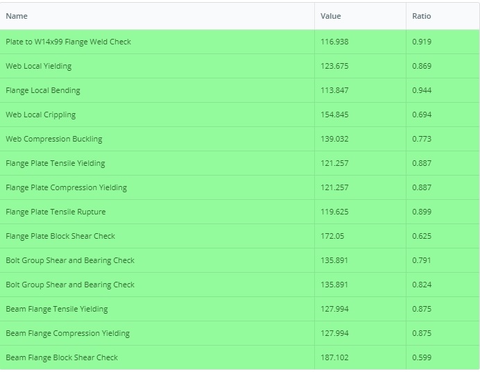
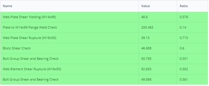
similarmente, o exemplo da versão LRFD pode ser encontrado neste link: Força do Elemento em Ruptura
Run This Example Yourself
Enter the W18x50, the W14x99 and the flange plates, and the module returns every check above with its utilization ratio and the clause behind it. Ele roda no navegador, sem nada para instalar.

Referências
- AISC 360-16, correspondente às especificações para aço estrutural
- Exemplos de projeto AISC v14.1 (Força do Elemento em Ruptura, Força do Elemento em Ruptura 13)
- Software de design de conexão SkyCiv: https://skyciv.com/structural-software/connection-design/
- Flange plate connection calculator: https://skyciv.com/structural-software/connection-design/flange-plate-connection-calculator/
