Análise e projeto de estruturas metálicas é regido por padrões como AS 4100:2020, que utiliza o método do estado limite para dimensionar membros estruturais de aço. Este método envolve o cálculo de cargas fatoradas e capacidades reduzidas para levar em conta a variabilidade nas condições de carga e nas propriedades do material.. Para o estado limite último (ULS) design para ficar satisfeito, o seguinte relacionamento deve ser verdadeiro:
\(ULS \;Fator * Carga ≤ Redução \;Fator * Capacidade)
Este documento descreve o procedimento para projetar uma barra de aço de acordo com AS 4100 usando o SkyCiv AS 4100:2020 Design de Membro de Aço módulo.
Conteúdo
Propriedades do Material
Fabricação
Na Austrália existem três formas típicas de fabricação de aço estrutural:
- Seções Laminadas a Quente: Boleto de aço (blocos) são aquecidos, enrolado em um moinho no formato desejado, então esfriou. Os exemplos incluem vigas/colunas universais, Canais de Flange Paralelos (PFC) e seções de ângulo.
- Seções formadas a frio: O tarugo de aço é prensado à temperatura ambiente no formato desejado. Os exemplos incluem seções ocas retangulares (RHS) e seções ocas circulares (CHS).
- Seções Fabricadas: Múltiplas placas planas laminadas a quente são soldadas entre si para formar uma seção de aço. Os exemplos incluem vigas/colunas soldadas.
Classe de aço
A Austrália tem vários tipos de aço (pontos fortes) que pode ser usado para projeto de acordo com AS 4100:2020. As disponibilidades de notas para diferentes tipos de seção estão descritas abaixo.
| Avaliar | Banco Mundial / Banheiro | Você pode encontrar uma variedade de tipos de conexão que atendem às suas necessidades sem lidar com sistemas de interface do usuário confusos que exigem uma curva de aprendizado íngreme até mesmo para começar / Você pode encontrar uma variedade de tipos de conexão que atendem às suas necessidades sem lidar com sistemas de interface do usuário confusos que exigem uma curva de aprendizado íngreme até mesmo para começar | PFC | ELA / UA | RHS / SHS | CHS |
|---|---|---|---|---|---|---|
| 250 | NÃO | NÃO | NÃO | NÃO | NÃO | SIM |
| 300 | SIM | SIM | SIM | SIM | NÃO | NÃO |
| 350 | SIM | SIM | SIM | SIM | SIM | SIM |
| 400 | SIM | NÃO | NÃO | NÃO | NÃO | NÃO |
| 450 | NÃO | NÃO | NÃO | NÃO | SIM | NÃO |
Força de rendimento
A resistência ao escoamento de uma seção de aço depende do seu grau, com classes mais altas tendo tensões de escoamento mais altas. A resistência ao escoamento das seções laminadas a quente e fabricadas varia dependendo da espessura da seção. Seções de aço mais espessas normalmente têm limites de escoamento mais baixos do que seções mais finas do mesmo tipo.
As seções formadas a frio são a exceção a esta regra e têm um limite de escoamento consistente para cada tipo de aço, independentemente da espessura da seção. Limite de escoamento e resistência da seção (tração) os valores de resistência podem ser calculados usando a Tabela 2.1 em AS 4100:2020.
Selecionando uma seção no SkyCiv AS 4100 Design de Membro de Aço
A SkyCiv AS 4100:2020 Design de Membro de Aço ferramenta permite aos usuários selecionar uma seção padrão do banco de dados SkyCiv ou criar uma seção completamente personalizada. Quando uma seção Padrão é selecionada, os limites de escoamento do flange e da alma são calculados automaticamente com base no tipo de aço usando AS 4100 Tabela 2.1. Quando uma seção personalizada é selecionada, o usuário deve inserir valores para a resistência ao escoamento do flange e da alma. As seções padrão também podem ser usadas com um tipo de aço personalizado, se especificado pelo usuário.

Capacidade da seção
Dobra
Capacidade do momento fletor da seção
AS 4100:2020 calcula a capacidade de momento fletor de uma seção de aço da seguinte forma:
\(M_s = f_y*Z_e\)
Onde fY é a tensão de escoamento do material, e Ze é o módulo da seção efetiva. O módulo de seção de uma forma é uma propriedade geométrica que quantifica a resistência à flexão de uma forma. Na engenharia estrutural usamos dois valores de módulo de seção, a elástico (Z) e plástico (S) módulo da seção. Observação, padrões de projeto em outras regiões às vezes trocam os símbolos para módulo de seção elástica e plástica.
O módulo da seção elástica assume toda a seção (forma) permanece elástico sob flexão, Ou seja. nenhuma parte da seção excede o limite de escoamento (fY) do material. Isso geralmente ocorre quando as fibras extremas da seção (topo/btm) alcançar rendimento. O módulo de seção elástica de uma seção é calculado da seguinte forma:
\(Z = \frac{I}{Y}\)
Onde I é o segundo momento da área e y é o centróide geométrico da forma.
O módulo da seção plástica assume que toda a seção atinge o limite de escoamento do material sob flexão, o que significa que partes da seção excederão o limite de escoamento e sofrerão deformação plástica. O módulo de seção plástica de uma seção é calculado da seguinte forma:
\(S = A_C*y_C + A_T*y_T \)
Onde AC e umT são as áreas em ambos os lados do Eixo Neutro Plástico (PNA), com sua distancia Yc / Yt são a distância do PNA ao centróide dessas áreas. Observação, a localização do PNA é igual à localização do centróide geométrico para formas simétricas, mas não igual à localização do centróide geométrico para formas assimétricas.
Classificação da Seção
Alguns formatos de aço podem ter elementos do formato que se curvam localmente antes de atingirem seu limite de escoamento, o que significa que a capacidade total do módulo da seção elástica/plástica não pode ser alcançada. Isso normalmente ocorre em maiores, formas mais finas, que são mais suscetíveis à flambagem local. AS 4100 usa o módulo de seção efetiva (Ela) valor para levar em conta a possibilidade de encurvadura local e reduzir a capacidade de flexão da seção de acordo. AS 4100 classifica seções em três categorias:
- Compactar: As seções compactas não são suscetíveis à flambagem local e podem atingir sua plena capacidade de momento plástico, o que significa que toda a seção pode atingir seu limite de escoamento sob flexão.
- Não compacto: Seções não compactas podem atingir o limite de escoamento nas fibras extremas da seção (capacidade de momento elástico) mas não podem atingir sua capacidade de momento plástico antes que ocorra a encurvadura local.
- Delgado: Seções delgadas não podem atingir sua capacidade de momento elástico antes que ocorra encurvadura local.

Esbeltez da seção
AS 4100 determina a classificação da seção calculando a esbelteza de cada elemento dentro de uma seção e encontrando o “elemento crítico” que irá dobrar na compressão primeiro. Para uma seção I, os elementos são divididos conforme mostrado abaixo. Os valores de esbeltez são calculados apenas para elementos pendentes, Ou seja. elementos que não são restringidos em ambas as direções. A área de conexão entre um flange e a alma (mostrado em branco abaixo) é restringido em ambas as direções e, portanto, não é suscetível à encurvadura local.
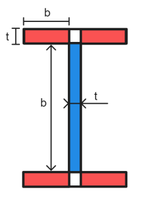
A esbeltez de um elemento plano é calculada da seguinte forma:
\(λ_e = \frac{b}{t}\sqrt{\fratura{f_y}{250}}\)
AS 4100 Tabela 5.2 contém valores para plasticidade e limites de esbeltez de rendimento (λepisódio & λei) para elementos de placa de compressão com base na distribuição de tensões, suporte de borda e tensões residuais. O elemento crítico de uma seção é o elemento com maior λe / λei Razão. Os valores de esbeltez deste elemento (λe) são usados para classificar toda a seção (referido como λs).
A partir da elevação do solo gerada a partir das elevações do Google λs ≤ λsp a seção é compacta. Para seções compactas, o módulo de seção efetiva é calculado da seguinte forma:
\(Z_e = Z_c = min(S,1.5*Z)\)
Onde S é o módulo da seção plástica, e Z é o módulo de seção elástica da seção. O termo Zc é usado indistintamente para o módulo de seção efetiva de uma seção compacta.
A partir da elevação do solo gerada a partir das elevações do Google λsp ≤ λs ≤ λseu a seção não é compacta. Para seções não compactas, o módulo de seção efetiva é calculado da seguinte forma:
\(Z_e = Z + [(\fratura{eu_{seu} – eu_{s}}{eu_{seu} – eu_{sp}})(Z_c-Z)]\)
Onde Zc é o módulo de seção efetiva para uma seção compacta.
A partir da elevação do solo gerada a partir das elevações do Google λs > λseu a seção é delgada. Para uma seção delgada com elementos de placa plana em compressão uniforme, o módulo de seção efetiva é calculado da seguinte forma:
\(Z_e = Z(\fratura{eu_{seu}}{λ_s})\)
Observação, o módulo de seção efetiva para seções ocas circulares ou elementos de placa plana com tensão na borda não suportada é calculado de forma diferente. Consulte AS 4100 Cláusula 5.2.5 para mais informações.
Calculando a capacidade de flexão da seção no SkyCiv AS 4100 Design de Membro de Aço
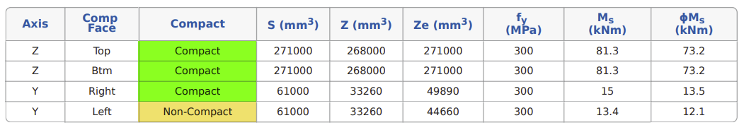
A SkyCiv AS 4100:2020 Design de Membro de Aço ferramenta calcula classificações de esbeltez e capacidades de flexão de seção para flexão positiva e negativa em torno de ambos os eixos principais. Os resultados da verificação de classificação de esbeltez para um 230 PFC são detalhados abaixo.

É evidente que os valores de esbeltez e a classificação da seção são diferentes dependendo da direção da flexão. Isso ocorre porque as distribuições de tensão e os valores de suporte das bordas mudam dependendo de quais elementos estão em compressão ou tração., resultando em diferentes valores limite de esbeltez.
Uma vez que a esbeltez da seção é conhecida, o módulo calcula a capacidade de momento fletor da seção (Cl.7.2.1.3 e deve satisfazer) sobre cada eixo principal para flexão positiva e negativa. Para formas simétricas (como seções I), este valor será o mesmo na direção positiva e negativa. As formas assimétricas terão diferentes capacidades de flexão de seção na direção de flexão positiva e negativa, como o 230 PFC mostrado no exemplo abaixo.
Cisalhamento
Capacidade de cisalhamento da seção
AS 4100 considera apenas a alma de uma seção como contribuindo para sua capacidade de cisalhamento. Daí a capacidade de cisalhamento de uma seção (Vv) é igual à capacidade de cisalhamento da alma. Reforços verticais podem ser adicionados a uma seção para aumentar sua capacidade de cisalhamento, se necessário. A capacidade de uma alma é calculada de forma diferente dependendo se a distribuição da tensão de cisalhamento através da alma é uniforme ou não uniforme. As seguintes distribuições de tensão de cisalhamento são assumidas para formatos de seção padrão:
| Forma | Distribuição de tensão de cisalhamento | |
|---|---|---|
| Direção Y | Direção Z | |
| Seção I | Uma cargas uniforme | Não Uniforme |
| Seção T | Não Uniforme | Não Uniforme |
| Canal de Flange Paralelo (PFC) | Uma cargas uniforme | Não Uniforme |
| Ângulos | Não Uniforme | Não Uniforme |
| RHS/SHS | Não Uniforme | Não Uniforme |
| CHS | Uma cargas uniforme | Uma cargas uniforme |
Distribuição Uniforme de Tensão de Cisalhamento
A capacidade de cisalhamento de uma seção com distribuição uniforme de tensões de cisalhamento (Vvocê) é calculado de forma diferente dependendo da esbelteza do painel web. Para uma teia não delgada, a capacidade é calculada da seguinte forma:
\(\fratura{d_p}{t_w} ≤ \frac{82}{\sqrt{\fratura{f_y}{250}}}\rightarrow V_u = V_w = 0.6*f_y*A_w\)
Nota para uma seção circular oca VC = 0,36*fY*A.
Quando a teia da seção é delgada, a capacidade é calculada da seguinte forma:
\(\fratura{d_p}{t_w} > \fratura{82}{\sqrt{\fratura{f_y}{250}}}\rightarrow V_u = V_b = α_v*V_w\)
\(α_v = \left[\fratura{82}{(\fratura{d_p}{t_w})\sqrt{\fratura{f_y}{250}}}\direito]^2)
Onde dp é a profundidade clara do painel da web (Ou seja. profundidade excluindo flanges), tC é a espessura do painel da web, fY é a resistência ao escoamento da alma e AC é a área seccional bruta da teia. Nota AC é calculado de forma diferente para seções soldadas e laminadas a quente. Para perfis laminados a quente, AC considera a profundidade da teia como a profundidade total da seção (d). Para seções soldadas, AC leva apenas a profundidade livre da alma entre os flanges (dp). Seções ocas retangulares também usam dp para cálculo de AC.
Distribuição não uniforme de tensão de cisalhamento
A capacidade de cisalhamento de uma seção com distribuição uniforme de tensões de cisalhamento (Vv) é calculado da seguinte forma:
\(V_v = \frac{2*V_u}{0.9+\deixou(\fratura{merda{vm}}{merda{vai}}\direito)} ≤ V_u\)
Onde Vvocê é a capacidade de cisalhamento da seção com uma distribuição uniforme de tensões de cisalhamento e f*vm /merdavai é a razão entre as tensões de cisalhamento máximas e médias de projeto na alma.
Calculando a capacidade de cisalhamento no SkyCiv AS 4100 Design de Membro de Aço
Calcula a capacidade de corte de uma seção em ambos os eixos principais. Eixo menor (Z) a capacidade de cisalhamento é calculada usando a contribuição dos flanges da seção, excluindo qualquer contribuição da seção web. Resultados dos cálculos de capacidade de cisalhamento para um 200 Você pode encontrar uma variedade de tipos de conexão que atendem às suas necessidades sem lidar com sistemas de interface do usuário confusos que exigem uma curva de aprendizado íngreme até mesmo para começar 22.3 estão detalhados abaixo.

compressão
Capacidade de compressão de seção
AS 4100 calcula a capacidade de compressão (Ns) de uma seção carregada concentricamente como segue:
\(N_s = k_f*A_n*f_y\)
Onde kf é o fator de forma da seção, An é a área líquida da seção transversal (área bruta excluindo penetrações/furos) e fY é o limite de escoamento da seção. O fator de forma de uma seção representa o quanto uma seção pode contribuir para sua capacidade de compressão antes que ocorra flambagem local.. O fator de forma é calculado da seguinte forma:
\(k_f = \frac{A_e}{A_g}\)
Onde Ag é a área bruta da seção, e ume é o “área efetiva” da seção, Ou seja. a área bruta da seção menos qualquer “ineficaz” áreas sob compressão. Uma área ineficaz é parte da seção que sofrerá flambagem antes de atingir sua capacidade de escoamento sob compressão.. As áreas efetivas são calculadas encontrando o “largura efetiva” de cada elemento de placa plana dentro de uma seção e recalculando a área da seção usando esses valores de largura ajustados. A largura efetiva de um elemento de placa plana é calculada da seguinte forma:
\(b_e = b\left(\fratura{eu_{ei}}{eu_{e}}\direito) ≤ b\)
Onde:
\(λ_e = \frac{b}{t}\sqrt{\fratura{f_y}{250}}\)
Observação, a maioria dos softwares de projeto usa o limite de escoamento da seção para cálculos de esbeltez do elemento, em vez da resistência ao escoamento específica da alma/flange. Isso sempre fornecerá um resultado conservador. Os valores b usados para λe cálculo são idênticos às dimensões usadas para verificações de esbeltez da seção de flexão (com o flange dividido em torno da alma), mas o b usado para be o cálculo é a largura total do flange/rede. λei é retirado de AS 4100 Tabela 6.2.4, dependendo do suporte da borda e das tensões residuais desse elemento.
A largura efetiva de uma seção circular oca é calculada da seguinte forma:
\(d_e = min(d_{o}\sqrt{\deixou(\fratura{eu_{ei}}{eu_{e}}\direito)}, d_{o}\deixou(\fratura{3*eu_{ei}}{eu_{e}}\direito)^ 2) ≤d_{o}\)
Onde:
\(λ_e = \left(\fratura{fazer}{t}\direito)\deixou(\fratura{f_y}{250}\direito)\)
Calculando a capacidade de compressão de seção no SkyCiv AS 4100 Design de Membro de Aço
O fator de forma e a capacidade de compressão da seção (Ns) são calculados para seções australianas padrão e seções personalizadas definidas pelo usuário. Resultados dos cálculos de capacidade de compressão de seção para um 610UB 125 estão detalhados abaixo.

Tensão
Capacidade de tensão da seção
AS 4100 calcula a capacidade de um membro de tensão (Nt) do seguinte modo:
\(N_t = min(UMA_{g}*f_{Y}\; ,\; 0.85*k_t*A_n*f_u)\)
Onde Ag é a área bruta da seção, An é a área líquida da seção transversal (área bruta excluindo penetrações/furos), fY é o limite de escoamento da seção, fvocê é a tração (final) resistência da seção e kt é o fator de correção da distribuição da força de tração. O kt usado no projeto varia dependendo do formato da seção e do tipo de conexão. Conexões que fornecem distribuição uniforme de força resultam em um kt fator de 1.0, conexões com distribuição desigual de força resultam em um kt fator entre 0.75-1.0.
Calculando a capacidade de tensão no SkyCiv AS 4100 Design de Membro de Aço
Nossa ferramenta permite aos usuários especificar a seção kt valor para usado em design. Um k inferiort valor resultará em uma capacidade de tensão de seção menor. O SkyCiv AS 4100 A calculadora do Member Design assume que não há furos significativos presentes na seção, portanto, An é considerado igual a Ag. Resultados dos cálculos da capacidade de tensão da seção para um 610UB 125 estão detalhados abaixo.

Capacidade dos membros
Dobra
Capacidade do momento fletor da barra
A capacidade de momento fletor de uma barra de aço nem sempre pode ser governada pela capacidade de momento fletor da seção (Ms). Isso ocorre porque os membros podem falhar por outro método antes que a capacidade da seção seja atingida. A flambagem por torção lateral é um método de falha comum para membros de aço longos/sem restrições, que ocorre quando a seção gira para longe de seu eixo maior (em direção ao seu eixo menor) reduzindo sua capacidade de momento na direção da flexão.

AS 4100 contém orientações sobre o cálculo da capacidade nominal dos membros (Mb), que fatora a capacidade da seção de um membro de aço (Ms) para levar em conta o impacto da esbeltez dos membros e das condições de restrição.
Membros com Retenção Lateral Total
Flange Crítico
O banzo crítico de uma seção transversal é o banzo que desviaria mais durante a encurvadura., eventualmente resultando em falha de flambagem por torção lateral. Este é normalmente o flange de compressão de um membro. As localizações críticas dos flanges para seções padrão sob carregamento vertical são mostradas abaixo.

Restrição lateral total
Membros mais curtos com alta rigidez rotacional/lateral têm menos probabilidade de girar fora do plano sob carga, reduzindo a probabilidade de falha de flambagem por torção lateral. Se um membro for suficientemente curto/rígido, será capaz de atingir a sua capacidade de momento de secção (Ms) antes que outro método de falha ocorra. Os membros que satisfaçam esta condição são considerados como tendo “Restrição lateral total”.
\(Cheio \; Lateral \; Restrição \; \rightarrow M_b = M_s\)
AS 4100 Cláusula 5.3.2 fornece orientação sobre o cálculo do limite de restrição lateral total para um membro. Seções Circulares Ocas (CHS) e seções ocas quadradas (SHS) não são suscetíveis à flambagem torcional lateral, pois possuem alta rigidez lateral/torcional e capacidades de momento de seção iguais em ambos os eixos. Portanto, geralmente se presume que essas seções alcançam restrição lateral total, independentemente do comprimento do membro.
Restrição lateral contínua
Os membros que possuem restrição contínua ao banzo crítico ao longo de todo o seu comprimento são considerados como tendo “Restrição lateral contínua”. A Restrição Lateral Contínua é considerada equivalente à Restrição Lateral Total para o cálculo da capacidade de flexão da barra (Mb).
Membros sem restrição lateral total
A capacidade de momento fletor de uma barra que não atinge a restrição lateral total é calculada da seguinte forma:
\(M_b = α_m*α_s*M_s ≤ M_s\)
Onde αm é o fator de modificação do momento e αs é o fator de redução de esbeltez. AS 4100 Cláusula 5.6 descreve o procedimento para calcular αm e αs.
Capacidade de flexão do membro do eixo menor
A capacidade de flexão de um membro dobrado em torno do seu eixo menor (Mb) é igual à capacidade da seção do eixo menor (Ms) sobre esse eixo. A capacidade da seção do eixo menor reflete a capacidade mínima que a seção pode atingir em relação a qualquer eixo, portanto, o membro não pode girar deste eixo para uma orientação menos favorável.
Calculando a capacidade de flexão dos membros no SkyCiv AS 4100 Design de Membro de Aço
Esta ferramenta realiza verificações completas de restrição lateral e calcula as capacidades de momento fletor da barra em torno de ambos os eixos principais para flexão positiva e negativa. Os usuários também têm a opção de selecionar “Restrição lateral contínua” para ignorar a verificação de restrição lateral completa. Os resultados dos cálculos da capacidade de flexão do membro para um 200UB22.3 de 3 m de comprimento são detalhados abaixo.

Observação, esta calculadora assume βs = -1.0 em todos os cálculos.
compressão
Capacidade de compressão de membros
A capacidade de compressão axial de um membro também é afetada pelo seu comprimento, rigidez lateral e condições de restrição. Irrestrito, membros mais longos provavelmente falharão devido à encurvadura por flexão antes da seção (abóbora) a capacidade é atingida. AS 4100 contém orientações sobre o cálculo da capacidade nominal dos membros (Nc), que leva em consideração a capacidade da seção de compressão (Ns) para levar em conta o impacto da esbeltez dos membros e das condições de restrição.
\(N_c = α_c*N_s ≤ N_s\)
Onde αc é o fator de redução da esbeltez do membro. Cláusula 6.3.3 como de 4100 fornece orientação sobre o cálculo de αc. A capacidade de compressão da barra deve ser verificada em ambos os eixos para encontrar o valor governante
\(α_c = ξ\left[1 – \sqrt{ 1 – \deixou( \fratura{ 90}{etc.} \direito)^ 2} \direito]\)
\(\xi = \frac{ \deixou( \fratura{ \lambda }{90} \direito)^ 2 + 1 + \e }{2 \deixou( \fratura{ \lambda }{90} \direito)^ 2}\)
\(\lambda = \lambda_n + α_aα_b\)
\(h = 0.00326(\lambda – 13.5) \geq 0\)
\(\alpha_a = \frac{2100(\lambda_n – 13.5)}{\lambda_n^2 – 15.3\lambda_n + 2050}\)
\(\lambda_n = \left( \fratura{o}{r} \direito) \sqrt{k_f} \sqrt{\fratura{f_y}{250}}\)
Onde (Le) e r são o comprimento efetivo e o raio de giração para o eixo de flambagem relevante. umab é a constante da seção membro, que é determinado usando AS 4100 Tabela 6.3.3. A lógica adotada por este módulo de cálculo para atribuição de αb está descrito abaixo:
| kf | Estresse residual | Tipo de Seção / Forma | tf ≤ 40? | umaB |
|---|---|---|---|---|
| < 1 | RH | Seção I | Sim | 0 |
| Não | 1.0 | |||
| Outro | - | 1.0 | ||
| Hardware | Seção I | Sim | 0.5 | |
| Não | 1.0 | |||
| RHS / SHS | - | 0 | ||
| Outro | - | 1.0 | ||
| FC | Qualquer | - | -0.5 | |
| = 1 | RH | Seção I | Sim | 0 |
| Não | 1.0 | |||
| Outro | - | 0.5 | ||
| Hardware | Seção I | - | 0 | |
| RHS / SHS | - | 0 | ||
| Outro | - | 0.5 | ||
| FC | Qualquer | - | -0.5 |
Observação:
– As seções ocas são consideradas sem alívio de tensão para o cálculo da constante da seção do membro (umab).
– Presume-se que as seções WB/WC e todas as seções personalizadas sejam fabricadas a partir de placas cortadas à chama ao calcular a constante da seção do membro (umab).
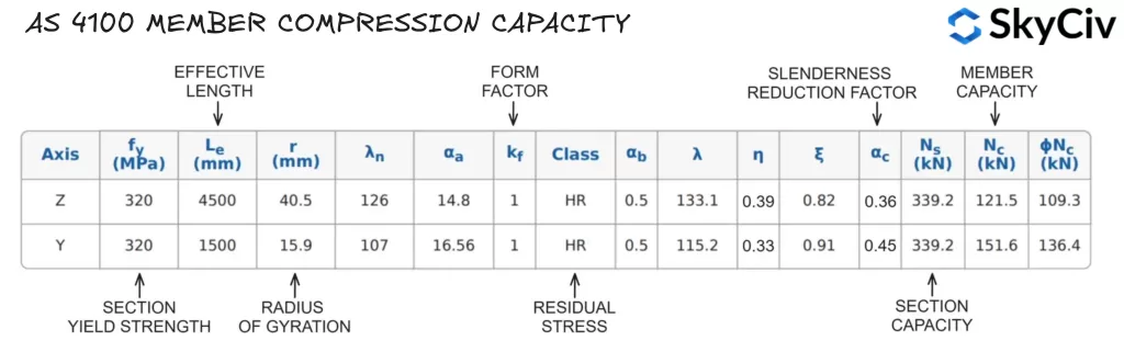
Calculando a capacidade de compactação de membros no SkyCiv AS 4100 Design de Membro de Aço
A ferramenta calcula a capacidade de compressão da barra em torno de ambos os eixos principais com base nos comprimentos de restrição e nos fatores de comprimento efetivo especificados pelo usuário. Resultados dos cálculos da capacidade de compressão da barra para um 200UB22.3 com comprimento irrestrito de 4.500 mm e 1.500 mm nos eixos Z e Y (respectivamente) estão detalhados abaixo.
Software de projeto estrutural SkyCiv
SkyCiv oferece uma ampla gama de softwares de análise estrutural e projeto de engenharia, incluindo:
- AS / NZS 1664 Design de Alumínio
- AS / NZS 4600 Design de terça
- AS 3600 Projeto de parede de cisalhamento de concreto
- AS 2870 Laje residencial em projeto de nível
- AS / NZS 1576 Projeto de andaimes
- AS 4055 Calculadora de cargas de vento

Desenvolvedor de software | Engenheiro estrutural
BEng (Civil), DipEng (Programas)