Software Steel Member Design para Eurocódigo 3 (EN 1993-1-1:2005)
Among the many design standards SkyCiv offers is Eurocode 3 (EN 1993-1-1:2005), Projeto de estruturas de aço. The module checks hot-rolled and welded steel members to the Ultimate Limit State, with a deflection check for the Serviceability Limit State. It runs in SkyCiv Structural 3D, where it reads the members, seções, materiais, forces and load combinations of your model.
Com este módulo você pode:
- Design I-shapes, Formas de T, ângulos, channels and hollow sections (RHS, SHS and CHS)
- Classify the cross-section (Aula 1, 2, 3 ou 4) for each load combination and limit state, with effective properties for Class 4 seções
- Check the resistance of cross-sections to tension, compressão, bending about both axes and shear, including the reduction of the yield strength for high shear
- Check the combined resistance of cross-sections (bending and axial force)
- Check the buckling resistance of members: flexível, torsional and torsional-flexural buckling in compression, lateral-torsional buckling in bending, and combined bending and axial compression with the interaction factors of Annex A or Annex B
- Split each member into lateral-torsional buckling segments, with C1 calculated from the bending moment diagram or entered by you
- Optionally check torsion (basic stress check) for I-shapes and rectangular hollow sections
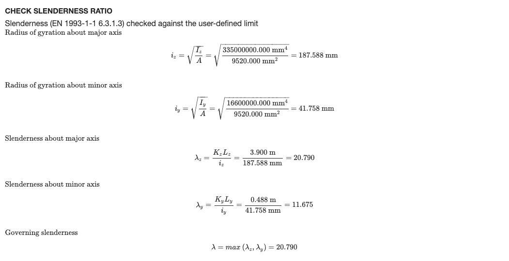
- Check the slenderness ratio (KL/r) against limits for compression and tension, optionally shown in the detailed report
- Check deflections against a span/deflection limit
- View the design ratios on the 3D model
- Export detailed step-by-step reports and a summary report, as HTML or PDF (Logotipo personalizado em Empreendimento)
- Execute o SkyCiv Designer (Executar designer) para encontrar a seção mais eficiente
- Totalmente verificado com resultados de terceiros
Suporte à versão atual
Seções
- I-Beam (I-shapes and H-shapes, hot-rolled or welded)
- T-Beam
- Ângulo
- o canal
- Retangular oco (RHS and SHS)
- Circular Oco (CHS)
The material must be steel. A Class 4 circular hollow section is outside the scope of the module and stops the check with an error message.
Unidades
The module only works in Métrica unidades. No modelo, abrir Configurações (barra superior) > Unidades e configure o sistema de unidades para Métrica.
Design in SkyCiv Structural 3D
Este módulo está totalmente integrado com nosso poderoso software de análise estrutural que permite aos engenheiros modelar, analisar e projetar com um modelo. Com um único clique, the software pulls your entire model and checks each member against the criteria of the Standard to determine whether or not it passes the requirements of these European Standards. Cargas, members and design parameters are imported automatically, including the load combinations from EN 1990.
Clique aqui para obter mais informações gerais sobre o nosso Integrado Software de projeto estrutural
Abrindo o módulo
- Resolva o modelo.
- Clique Projeto na barra superior.
- No Selecione um módulo de design, escolher Design de placa de base de aço Eurocode.
- No Qual código de design você gostaria de iniciar?, escolha Eurocódigo 3 (EN 1993-1-1:2005), então clique Começar.
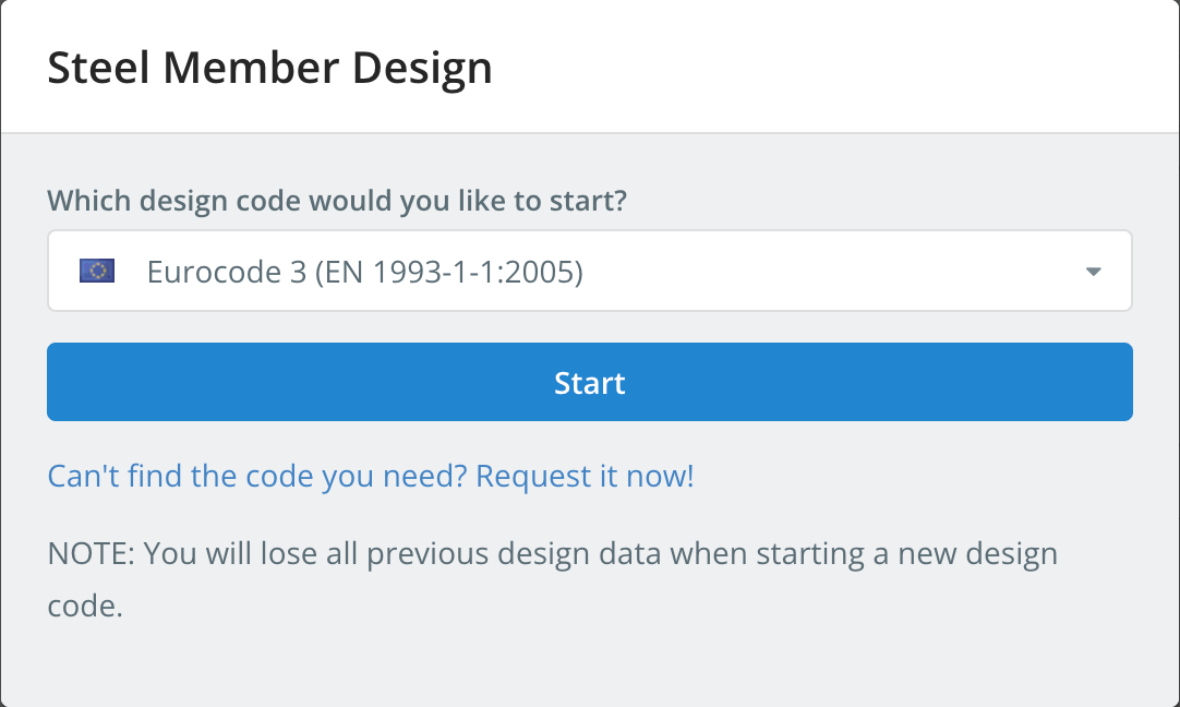
Starting a design code deletes the design data of the previous one. To switch codes later, usar Iniciar novo código no Projeto cardápio.
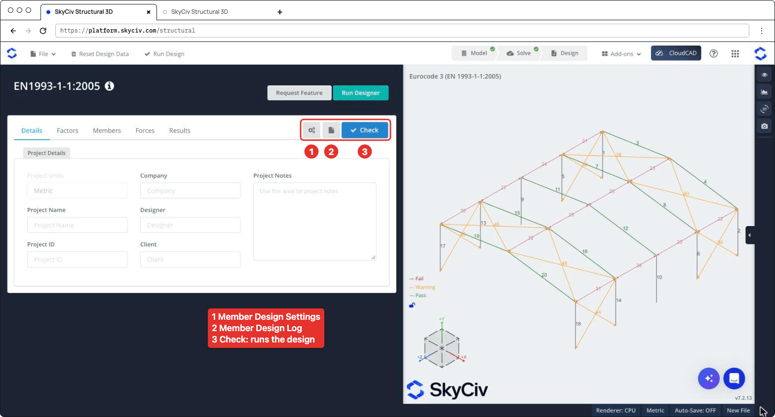
O painel de design abre à esquerda, com o modelo 3D à direita. O cabeçalho mostra o código, mais Solicitar recurso e Executar designer. À direita da barra de guias há três botões: as configurações (engrenagem) botão, que abre Configurações de design de membros, o botão de registro, que abre o Registro de design de membros, e Verificar, que executa a verificação de design. As guias são Detalhes, Fatores, Membros, Forças e Resultados.
Configurações de design de membros
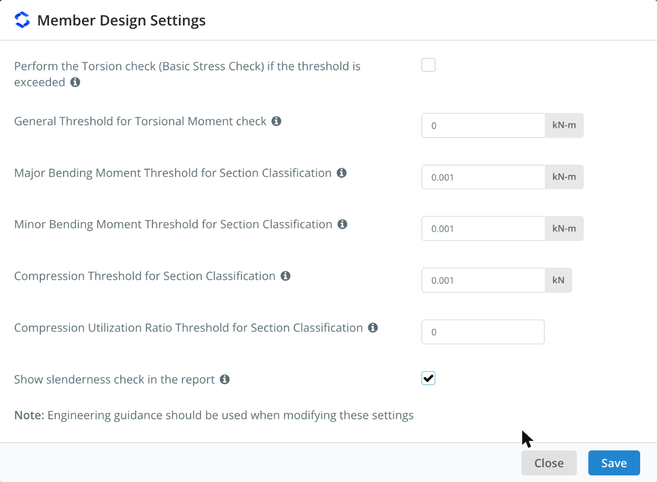
Clique no botão de engrenagem para abrir Configurações de design de membros. Passe o mouse sobre o ícone ℹ próximo a uma configuração para ver sua descrição.
| Contexto | Padrão | Descrição |
|---|---|---|
| Perform the Torsion check (Verificação básica de estresse) if the threshold is exceeded | Desmarcado | Runs the torsion check of I-shapes and rectangular hollow sections when the torsional moment exceeds the threshold. Quando desmarcado, the torsion check is skipped whatever the threshold |
| General Threshold for Torsional Moment check | 0 kN-m | The torsional moment (in absolute value) above which the torsion check is performed, for all members whose Tlimite é auto no Membros aba |
| Major Bending Moment Threshold for Section Classification | 0.001 kN-m | Bending about the major axis is included in the overall section classification of a limit state only when the moment exceeds this value |
| Minor Bending Moment Threshold for Section Classification | 0.001 kN-m | O mesmo, for bending about the minor axis |
| Compression Threshold for Section Classification | 0.001 kN | Compression is included in the overall section classification of a limit state only when the compression force exceeds this value |
| Compression Utilization Ratio Threshold for Section Classification | 0 | Compression is included in the overall section classification only when its utilization ratio exceeds this value. It applies to all the limit states other than compression |
| Show slenderness check in the report | Desmarcado | Adds the slenderness check to the detailed report of each member, Vejo Slenderness Ratio Check abaixo |
The classification thresholds keep very small forces from governing the class of a section: por exemplo, a beam with a negligible axial force is not classified as if it were in pure compression. Como a caixa de diálogo observa, orientação de engenharia deve ser usada quando você altera essas configurações. Clique Salve aplicar.
Detalhes
No Detalhes guia você pode inserir os detalhes do projeto (Companhia, Nome do Projeto, Designer, Código do projeto, Cliente e Notas do projeto). Você não precisa preenchê-los, but anything you enter is shown in your reports. Unidades de Projeto mostra Métrica e não pode ser alterado aqui.
Fatores
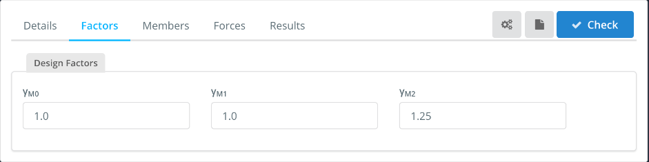
A Fatores tab shows the partial factors for resistance, which you can change:
| Fator | Used for | Padrão |
|---|---|---|
| cM0 | Resistance of cross-sections | 1.0 |
| cM1 | Resistance of members to instability (flambagem) | 1.0 |
| cinclui cálculos detalhados passo a passo | Resistance of cross-sections in tension to fracture (net section) | 1.25 |
Membros
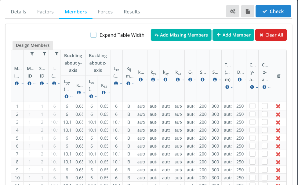
A Membros guia lista os membros do design, with one row for each member of the model. ID de membro(s), ID de material, ID da seção e L come from the model. The buckling lengths and the other parameters are filled in with default values that you can change. Hover over the ℹ icon in a column header to see its description.
- Expandir largura da tabela: shows the full column headers and values, with a horizontal scroll bar.
- Add Missing Members, mas podem ser modificados, se necessário, antes da verificação final do projeto e Clear All: add the model members that are not in the table, add a design member, or remove all of them. Enter several member IDs, separados por vírgulas, no ID de membro(s) to design them as a single design member.
| Coluna | Descrição | Padrão |
|---|---|---|
| Lyy, Kyy | Buckling length and effective length factor for flexural buckling about the y-y (principal) neutro, used to calculate NC3.1.2.1-9 | Lyy = member length, Kyy from the end fixity of the member |
| Lzz, Kzz | O mesmo, about the z-z (menor) neutro | Lzz = member length, Kzz from the end fixity of the member |
| LC3.1.2.1-9 | Buckling length for lateral-torsional buckling. Enter the member length, or comma-separated lengths, one for each segment between lateral restraints | Comprimento do membro |
| Kij método | Method used to calculate the interaction factors: A (Annex A, alternative method 1) ou B (Anexo B, alternative method 2) | B |
| kyy, kyz, kzy, kzz | Interaction factors for bending and axial compression (Eq. 6.61 e 6.62). Com auto, they are calculated with the method chosen in Kij método | auto |
| C1 | Moment modification factor for the elastic critical moment MC3.1.2.1-9. Com auto, it is calculated from the bending moment diagram of each segment. Enter a single value for all the segments, or comma-separated values, one for each segment | auto |
| SRC, SRT | Slenderness limits in compression and in tension, Vejo Slenderness Ratio Check abaixo | 200, 300 |
| Tlimite | Torsional moment threshold for the torsion check of this member. Com auto, the general threshold of the settings is used. The torsion check must be ticked in the settings | auto |
| DefL | Razão de limite de deflexão: the member passes when span/deflection is at least this value | 250 |
| Cantilever y-axis, Cantilever z-axis | Tick if the deflection check should consider the member as supported at one end only, for deflection along that axis | Desmarcado |
Por exemplo, por um 10.1 m rafter with purlins every 2.02 m, entrar 2.02,2.02,2.02,2.02,2.02 no LC3.1.2.1-9. The lengths must add up to the member length (dentro de 1%). Each segment is then checked for lateral-torsional buckling with its own length and C1. If you enter a single length that is different from the member length, C1 can’t be calculated automatically and must be entered as a number.
Forças
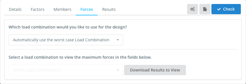
A Forças tab sets the load combination used in the design. Por padrão, Automatically use the worst case Load Combination checks every strength load combination of the model and reports the worst one for each check. You can also select a single load combination. Serviceability combinations are not listed here: they are used for the deflection check.
To view the forces of a load combination, select it in Select a load combination to view the maximum forces in the fields below, e clique Download Results to View.
Resultados
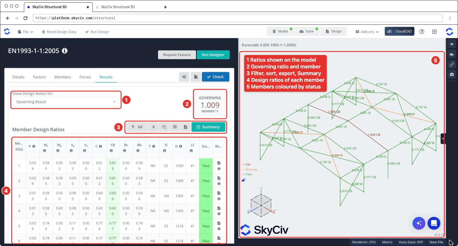
Clique Verificar para executar a verificação do projeto. A Resultados guias mostram (numbered as in the screenshot below):
- Mostrar taxas de design para: chooses which ratios are shown on the 3D model, por exemplo Resultado Governante, Membros falhados, a single check or the Worst Load Combination.
- GOVERNAR: a proporção mais alta e seu membro.
- A toolbar to filter the members (Tudo, Failed, Esses relatórios fornecem cálculos manuais muito mais detalhados das verificações que estão sendo feitas para o membro ou Aviso membros, or the members of a section), reset the sorting, copy the table, download it as CSV, download all the member reports as HTML, e abra o Resumo relatório.
- A Proporções de Design de Membros tabela, com um Status (Passar, Warn ou Falhou) and the report icon of each member. Passe o mouse sobre o ícone ℹ no cabeçalho de uma coluna para ver a cláusula à qual ele se refere.
- The 3D view, where each member is coloured Falhou, Aviso ou Passar and labelled with its governing ratio and check.
| Coluna | Verificar | Cláusula |
|---|---|---|
| P | Axial force, tensão ou compressão | 6.2.3 ou 6.2.4 |
| Mz | Bending about the major axis | 6.2.5 |
| MY | Bending about the minor axis | 6.2.5 |
| VY, Vz | Cisalhamento | 6.2.6 |
| C | Ações combinadas, resistance of cross-sections | 6.2.1 |
| CB | Combined bending and axial compression, buckling resistance of members | 6.3.3 |
| Bc | Buckling resistance of compression members | 6.3.1 |
| Bb | Lateral-torsional buckling resistance | 6.3.2 |
| T | Torção (basic stress check), NR when it is not performed | 6.2.7 |
| Sl | Governing slenderness λ of the member (not a ratio) | |
| D | Span/deflection of the member (not a ratio) | |
| LC | Load combination of the governing result |
A member fails when one of its strength ratios is above 1.0. The slenderness and deflection checks are not part of the governing ratio: when the slenderness exceeds its limit, or the span/deflection is below DefL, a Sl ou D value is highlighted and the member status is Warn. Their ratios to the limits are shown on the 3D model (por exemplo 0.797 Sl) E no Resumo relatório.
Relatórios
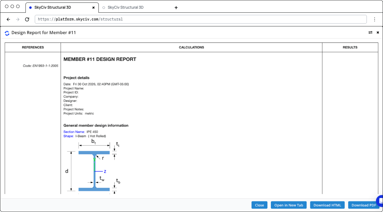
Click the report icon of a member to open its design report, em um Relatório de design para membro #n dialogar com Fechar, Abrir em nova guia, Baixar HTML e Baixar PDF. The report shows the references (clauses), the calculations and the result (STATUS PASS ou FALHOU) of each check:
- Detalhes do projeto e General member design information: the section, its shape and fabrication (hot-rolled or welded), the material properties and the design parameters
- Design Internal Forces: the governing forces used for each check
- The checks of axial strength (tensão ou compressão), axial buckling strength, flexural strength about the major and minor axes, lateral-torsional buckling resistance, interaction of combined resistance, interaction of combined buckling, shear strength along y and z and, when performed, torção
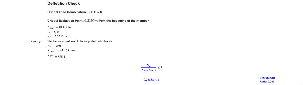
- Deflection Check: the critical serviceability load combination and position, the span, the maximum deflection and the ratio to the limit
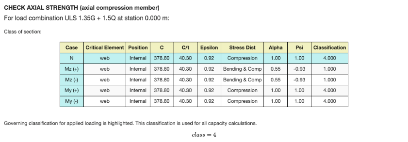
Each check gives the load combination and station that govern it, and the section classification table for that limit state: the class of each element (rede, flanges) for the axial force and for bending about each axis, with the governing class highlighted. For a Class 4 seção, the effective properties are used. When the shear force is high (6.2.8), the reduced yield strength is used for the resistances.
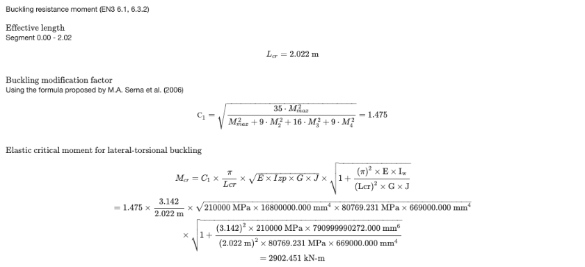
The lateral-torsional buckling check is calculated for the segment where the governing station is, with its LC3.1.2.1-9 e C1. When C1 é auto, it is calculated from the moments along the segment with the formula proposed by Serna et al. (2006). The report then gives MC3.1.2.1-9, the non-dimensional slenderness, the buckling curve and the reduction factor χLT.
The deflection check is performed when the model has serviceability load combinations and DefL é melhor que 0. Otherwise the report says that the deflection check was skipped.
Clique Resumo on the Results tab to open the summary report. Ele lista os detalhes do projeto (código de design, user name and unit system), the design factors, os materiais, the section dimensions and properties, the properties of each member (buckling lengths, LC3.1.2.1-9, C1, Cm factors and limits), the results of all the members and the definitions of the symbols.
Verificações realizadas
Here are the details of some of the checks performed by the module.
Slenderness Ratio Check
Each member is checked against the slenderness limits entered in the Membros aba: SRC for members in compression (200 por padrão) e SRT for members in tension or without axial force (300 por padrão). The slenderness is calculated about both axes from the effective length and the radius of gyration about the same axis:
- λz = KzLz / Iz about the major axis, with iz = √(Iz / A)
- λY = KYLY / IY about the minor axis, with iY = √(IY / A)
The governing slenderness λ = max(λz, λY) is divided by the limit, and the member passes when this ratio is 1.0 ou menos. The slenderness check is listed in the Sl column of the Results tab.
To show this check in the detailed report of each member, open the settings (the gear button next to Verificar) and tick Show slenderness check in the report. It’s off by default.
The report then has a Check Slenderness Ratio section after the buckling check, with the radii of gyration, the slenderness about each axis, the governing slenderness and its ratio to the compression and/or tension limit, with a PASS or FAIL status.