O que é uma carga excêntrica?
Uma carga excêntrica é qualquer carga que seja não aplicado ao centróide do membro. Na análise de elementos finitos, cargas pontuais, cargas distribuídas, e outras forças são geralmente aplicadas ao centróide da seção (Ou seja. o centro geométrico da seção). Contudo, em certos cenários você pode querer aplicar uma força fora do centro – por exemplo, aplicando uma carga ao flange de uma viga I, em vez da web. Supondo que esta seja uma carga lateral, isso criará uma força de torção e um comportamento de carga geral diferente no membro.
Como aplicar cargas excêntricas a um modelo
Aqui, mostraremos um exemplo de como você pode usar Links Rígidos aplicar uma carga tão excêntrica. Usando links rígidos, podemos transferir a carga do centróide da barra para um local diferente. Links Rígidos são extremamente úteis para este tipo de trabalho, pois calcula automaticamente o momento resultante e outras forças de um local para outro.
Vá para S3D e crie um novo modelo. A continuação, selecione a ferramenta caneta no painel direito ou tocando V. Clique uma vez para colocar o primeiro nó na origem, em seguida, desenhe para cima cerca de 2m (6.5ft) para criar uma coluna.
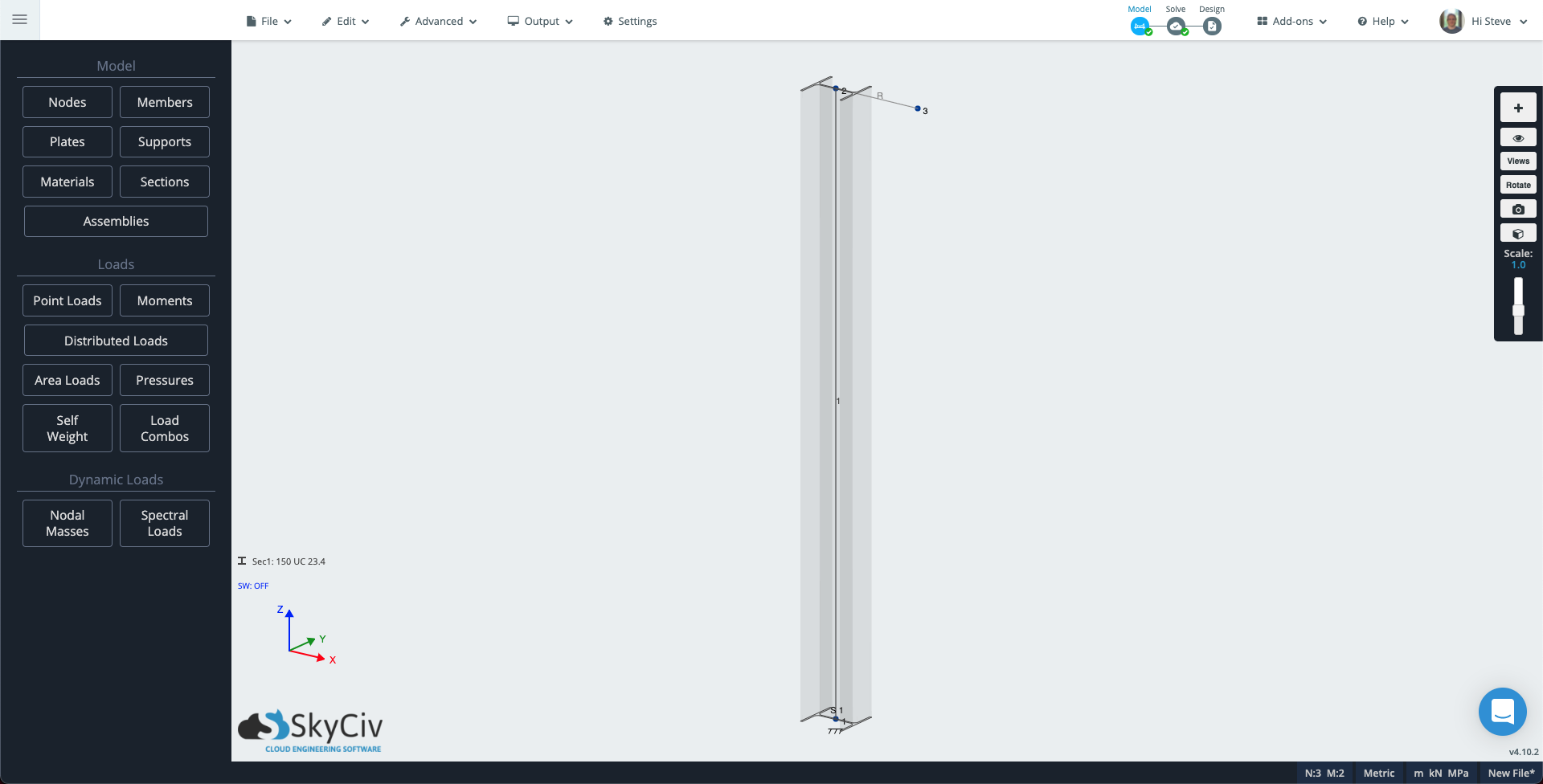
No canto pelo sistema de coordenadas, clique será usado: será usado, então no painel esquerdo, clique Construtor para abrir o construtor de seção. Escolha uma seção de coluna, para esta nota técnica selecionei um australiano 150UC23.4, isso é cerca de 6×6 I seção para nossos amigos imperiais. No painel esquerdo, clique em suportes e adicione suporte fixo no Node 1.
Agora vamos adicionar outra barra para que possamos criar uma carga excêntrica que induza torção e outra que crie um efeito de flambagem em nosso pilar.
Para ver a orientação da sua coluna, clique no ícone de visibilidade no painel direito e selecione 3Membros D. Use a ferramenta caneta para desenhar um desenho de 300mm (1ft) membro na direção X do topo da coluna. A partir da elevação do solo gerada a partir das elevações do Google “3Membro D” está ligado, você verá que este membro usa a seção de coluna. Clique no novo membro, então no painel esquerdo, altere o atributo type para Rígido e clique Aplicar.
Seu modelo deve ser semelhante ao abaixo:
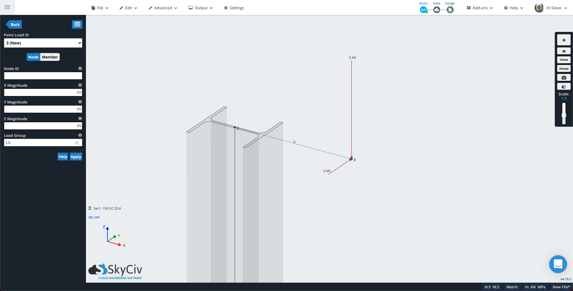
Clique em Cargas pontuais no painel esquerdo. Preencha os atributos com os seguintes valores:
- Node ID: 3
- Da Magnitude: -5 (Se o seu modelo usa o eixo Y como vertical, adicione este valor à magnitude Y).
- Grupo de carga: Carga de flambagem
Clique em aplicar e a carga pontual será adicionada ao modelo. O ID de carga pontual aumentará para 2 (Novo) então adicione outra carga para criar torção na coluna:
- Node ID: 3
- E Magnitude: 2 (Se o seu modelo usa o eixo Y como vertical, adicione este valor à Magnitude Z).
- Grupo de carga: Carga de torção
Nó 3 do seu modelo agora deve ser parecido com o seguinte.
Execute o solucionador, então abra o modo de renderização – o ícone do cubo no painel direito. Altere o menu suspenso no painel esquerdo para Carga de flambagem, a escala de deflexão para Auto, e o menu suspenso Resultados de membros para Soma de deslocamento. Agora você pode ver como a primeira carga excêntrica está causando um efeito de flambagem.
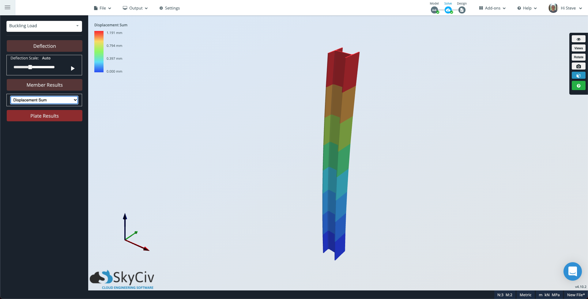
Observe que se você quiser ver uma subdivisão mais detalhada do membro, você pode ir para Configurações hip-delete-não usado Os métodos de combinação de carga disponíveis incluem, mudar o Pontos de Avaliação por Membro para um número adequado e execute resolver novamente.
Agora mude o menu suspenso de Carga de flambagem para Carga de torção quanto pelo Resultados de membros para Estresse de torção. Nesse caso, o membro aparecerá em cinza, pois a carga de torção é consistente em todo o membro.
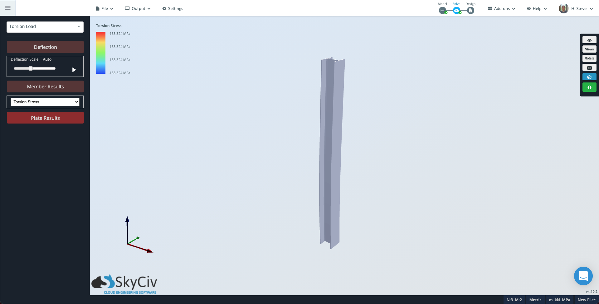
Observe que a escala de contorno no canto superior esquerdo ainda mostra a magnitude da torção que a coluna está sofrendo.