Exemplo de design da placa de base usando AISC 360-22 e ACI 318-19
Declaração de problemas
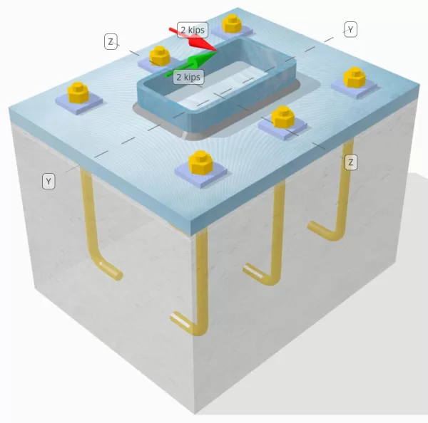
Determinar se a conexão de placa de coluna para base projetada é suficiente para um VY = 2-KIP e VZ = 2 frango cargas de cisalhamento.
Dados dados
Coluna:
Seção de coluna: Hss7x4x5/16
Área da coluna: 7.59 no2
Material da coluna: A36
Placa Base:
Dimensões da placa de base: 12 em x 14 no
Espessura da placa de base: 3/4 no
Material da placa de base: A36
Grout:
Espessura do rejunte: 0.25 no
Concreto:
Dimensões concretas: 12 em x 14 no
Espessura do concreto: 10 no
Material concreto: 3000 psi
Rachado ou sem crack: Rachado
Âncoras:
Diâmetro da âncora: 1/2 no
Comprimento eficaz de incorporação: 8 no
Espessura da arruela de placa: 0.25 no
Conexão com arruela de placa: Soldado na placa de base
Soldas:
Tamanho da solda: 1/4 no
Classificação de metal de enchimento: E70XX
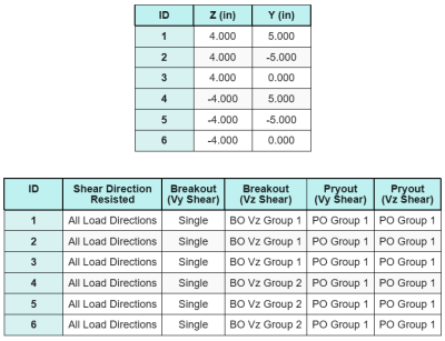
Dados de âncora (a partir de Calculadora Skyciv):
Modelo na ferramenta gratuita SkyCiv
Modele o design da placa de base acima usando nossa ferramenta online gratuita hoje mesmo! Não é necessária inscrição.
Definições
Caminho de carga:
O design segue as recomendações de Guia de projeto AISC 1, 3Edição RD, e ACI 318-19. As cargas de cisalhamento aplicadas à coluna são transferidas para a placa de base através das soldas, e depois para o concreto de apoio através do hastes de ancoragem. Fiction and Shear Lugs não são considerados neste exemplo, Como esses mecanismos não são suportados no software atual.
Por padrão, o aplicado shear load is distributed to all anchors, seja através do uso de arruelas de placas soldadas ou por outros meios de engenharia. A carga transportada por cada âncora é determinada usando os três (3) casos indicados em ACI 318-19 Cláusula 17.7.2 and Fig. R17.7.2.1b. Cada âncora então transfere a carga para o concreto de suporte abaixo. A distribuição de carga de acordo com estas referências também é utilizada na verificação da resistência ao cisalhamento do aço da ancoragem para garantir a continuidade nas suposições de transferência de carga.
Como uma alternativa, O software permite uma suposição simplificada e mais conservadora, onde toda a carga de cisalhamento é atribuída apenas ao âncoras mais próximas da borda carregada. Nesse caso, A verificação de capacidade de cisalhamento é realizada apenas nessas âncoras de borda.
Grupos de âncora:
A Software de design de placa de base SkyCiv inclui um recurso intuitivo que identifica quais âncoras fazem parte de um grupo âncora para avaliar Breakout de cisalhamento de concreto e Pryout de cisalhamento de concreto falhas.
A grupo âncora é definido como duas ou mais âncoras com áreas de resistência projetadas sobrepostas. Nesse caso, as âncoras agem juntas, e sua resistência combinada é verificada contra a carga aplicada no grupo.
A âncora única é definido como uma âncora cuja área de resistência projetada não se sobrepõe a nenhum outro. Nesse caso, A âncora age sozinha, e a força de cisalhamento aplicada nessa âncora é verificada diretamente contra sua resistência individual.
Essa distinção permite que o software capture o comportamento do grupo e o desempenho individual da âncora ao avaliar os modos de falha relacionados ao cisalhamento.
Cálculos passo a passo
Verificar #1: Calcule a capacidade de solda
O primeiro passo é calcular o Comprimento total da solda Disponível para resistir ao cisalhamento. Como a placa de base é soldada ao longo do perímetro da seção da coluna, O comprimento total da solda é obtido resumindo as soldas por todos os lados.
\( EU_{soldar} = 2 \deixou( b_{col} – 2r_{col} – 2t_{col} \direito) + 2 \deixou( d_{col} – 2r_{col} – 2t_{col} \direito) \)
\( EU_{soldar} = 2 \vezes (4\,\texto{no} – 2 \vezes 0,291 , text{no} – 2 \vezes 0,291 , text{no}) + 2 \vezes (7\,\texto{no} – 2 \vezes 0,291 , text{no} – 2 \vezes 0,291 , text{no}) = 17.344 , text{no} \)
Usando este comprimento de solda, as forças de cisalhamento aplicadas no y- e as direção z são divididas para determinar a média Força de cisalhamento por unidade de comprimento em cada direção:
\( v_{uy} = frac{V_y}{EU_{soldar}} = frac{2\,\texto{kip}}{17.344\,\texto{no}} = 0,11531 , text{kip/in} \)
\( v_{para} = frac{V_z}{EU_{soldar}} = frac{2\,\texto{kip}}{17.344\,\texto{no}} = 0,11531 , text{kip/in} \)
A cisalhamento resultante demanda por unidade de comprimento é então determinado usando a raiz quadrada da soma dos quadrados (Os métodos de combinação de carga disponíveis incluem) método.
\( r_u = sqrt{(v_{uy})^ 2 + (v_{para})^ 2} \)
\( r_u = sqrt{(0.11531\,\texto{kip/in})^ 2 + (0.11531\,\texto{kip/in})^ 2} = 0,16308 , text{kip/in} \)
A continuação, A capacidade de solda é calculada usando AISC 360-22 Eq. J2-4, com o coeficiente de força direcional tomado como KDS = 1,0 Para uma seção HSS. A capacidade de solda para um 1/4 em solda é determinado como:
\( \Phi r_n = phi 0.6 F_{Exx} E_w k_{ds} = 0.75 \vezes 0.6 \vezes 70 , text{ksi} \vezes 0,177 , text{no} \vezes 1 = 5.5755 , text{kip/in} \)
Também é necessário verificar os metais base, A coluna e a placa de base, usando AISC 360-22 Eq. J4-4 Para obter a força de ruptura de cisalhamento. Isso dá:
\( \phi r_{nbm, col} = phi 0.6 F_{u _col} t_{col} = 0.75 \vezes 0.6 \vezes 58 , text{ksi} \vezes 0,291 , text{no} = 7.5951 , text{kip/in} \)
\( \phi r_{nbm, pb} = phi 0.6 F_{u _bp} t_{pb} = 0.75 \vezes 0.6 \vezes 58 , text{ksi} \vezes 0,75 , text{no} = 19.575 , text{kip/in} \)
\( \phi r_{nbm} = min esquerda( \phi r_{nbm, pb},\, \phi r_{nbm, col} \direito) = min(19.575\,\texto{kip/in},\, 7.5951\,\texto{kip/in}) = 7.5951 , text{kip/in} \)
Como o estresse real da solda é menor do que as capacidades de metal de solda e metal base, 0.16308 KPI < 5.5755 KPI e 0.16308 KPI < 7.5951 KPI, A capacidade de solda de design é suficiente.
Verificar #2: Calcule a capacidade de fuga de concreto devido ao cisalhamento VY
Capacidade da borda perpendicular:
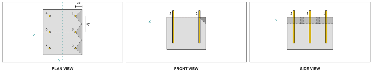
Do layout, Âncoras 1 e 4 estão mais próximos da borda e têm o Distância CA1 mais curta. Usando esses valores de CA1 para projetar os cones de falha, O software identificou essas âncoras como âncoras únicas, já que seus cones projetados não se sobrepõem. O apoio também foi determinado como não um membro estreito, Portanto, a distância CA1 é usada diretamente sem modificação.
Lembre -se de que a força de cisalhamento é assumida como distribuída entre todas as âncoras. O cálculo para o Vy Carga de cisalhamento aplicado a cada âncora é:
\( V_{Fa perp} = frac{V_y}{n / D} = frac{2\,\texto{kip}}{6} = 0,33333 , text{kip} \)
Vamos considerar Âncora 1. A área máxima projetada de uma única âncora é calculada usando ACI 318-19 Eq. 17.7.2.1.3.
\( UMA_{Vco} = 4.5 (c_{A1, S1})A partir da elevação do solo gerada a partir das elevações do Google 4.5 \vezes (2\,\texto{no})^2 = 18 , text{no}^ 2 \)
A área projetada é então determinada a partir da largura e altura do cone de falha projetado.
\( B_{Vc} = min(c_{deixou,s1},\, 1.5c_{A1, S1}) + \min(c_{direito,s1},\, 1.5c_{A1, S1}) \)
\( B_{Vc} = min(10\,\texto{no},\, 1.5 \vezes 2 , text{no}) + \min(2\,\texto{no},\, 1.5 \vezes 2 , text{no}) = 5 , text{no} \)
\( a força de deslizamento é a soma da força horizontal resultante da pressão ativa do solo no lado ativo do solo e a força horizontal resultante da presença da sobrecarga{Vc} = min(1.5c_{A1, S1},\, t_{conc}) = min(1.5 \vezes 2 , text{no},\, 10\,\texto{no}) = 3 , text{no} \)
\( UMA_{Vc} = B_{Vc} a força de deslizamento é a soma da força horizontal resultante da pressão ativa do solo no lado ativo do solo e a força horizontal resultante da presença da sobrecarga{Vc} = 5 , text{no} \vezes 3 , text{no} = 15 , text{no}^ 2 \)
O próximo passo é usar Equações 17.7.2.2.1a e 17.7.2.2.1b Para calcular a força básica de uma única âncora. A capacidade de governo é tomada como o menor valor.
\( V_{b1} = 7 \deixou( \fratura{\min(o,\, 8d_a)}{d_a} \direito)^{0.2} \sqrt{\fratura{d_a}{\texto{no}}} \lambda_a sqrt{\fratura{f’_c}{\texto{psi}}} \deixou( \fratura{c_{A1, S1}}{\texto{no}} \direito)^{1.5} \,\texto{Detalhes e parâmetros do modelo} \)
\( V_{b1} = 7 \times left( \fratura{\min(8\,\texto{no},\, 8 \vezes 0,5 , text{no})}{0.5\,\texto{no}} \direito)^{0.2} \times sqrt{\fratura{0.5\,\texto{no}}{1\,\texto{no}}} \vezes 1 \times sqrt{\fratura{3\,\texto{ksi}}{0.001\,\texto{ksi}}} \times left( \fratura{2\,\texto{no}}{1\,\texto{no}} \direito)^{1.5} \vezes 0,001 , text{kip} \)
\( V_{b1} = 1.1623 , text{kip} \)
\( V_{b2} = 9 \lambda_a sqrt{\fratura{f’_c}{\texto{psi}}} \deixou( \fratura{c_{A1, S1}}{\texto{no}} \direito)^{1.5} \,\texto{Detalhes e parâmetros do modelo} \)
\( V_{b2} = 9 \vezes 1 \times sqrt{\fratura{3\,\texto{ksi}}{0.001\,\texto{ksi}}} \times left( \fratura{2\,\texto{no}}{1\,\texto{no}} \direito)^{1.5} \vezes 0,001 , text{kip} = 1.3943 , text{kip} \)
\( V_b = min(V_{b1},\, V_{b2}) = min(1.1623\,\texto{kip},\, 1.3943\,\texto{kip}) = 1.1623 , text{kip} \)
A continuação, a Parâmetros de capacidade de quebra são determinados. A fator de efeito de borda de fuga é calculado de acordo com ACI 318-19 Cláusula 17.7.2.4, quanto pelo fator de espessura é calculado de acordo com Cláusula 17.7.2.6.1.
\( \Psi_{ed,V} = min esquerda(1.0,\, 0.7 + 0.3 \deixou( \fratura{c_{A2, S1}}{1.5c_{A1, S1}} \direito) \direito) = min esquerda(1,\, 0.7 + 0.3 \times left( \fratura{2\,\texto{no}}{1.5 \vezes 2 , text{no}} \direito) \direito) = 0.9 \)
\( \Psi_{h,V} = max esquerda( \sqrt{ \fratura{1.5c_{A1, S1}}{t_{conc}} },\, 1.0 \direito) = max esquerda( \sqrt{ \fratura{1.5 \vezes 2 , text{no}}{10\,\texto{no}} },\, 1 \direito) = 1 \)
Finalmente, ACI 318-19 Cláusula 17.7.2.1(uma) é usado para determinar a capacidade de fuga de concreto de uma única âncora em cisalhamento. A capacidade calculada para o cisalhamento de VY na direção perpendicular é 0.69 kips.
\( \phi V_{cb perp} = phi esquerda( \fratura{UMA_{Vc}}{UMA_{Vco}} \direito) \Psi_{ed,V} \Psi_{c,V} \Psi_{h,V} V_b \)
\( \phi V_{cb perp} = 0.65 \times left( \fratura{15\,\texto{no}^ 2}{18\,\texto{no}^ 2} \direito) \vezes 0.86 \vezes 1 \vezes 1 \vezes 1.1623 , text{kip} = 0,56661 , text{kip} \)
A capacidade calculada para Vy cisalhamento no perpendicular direção é 0.56 kips.
Capacidade de borda paralela:
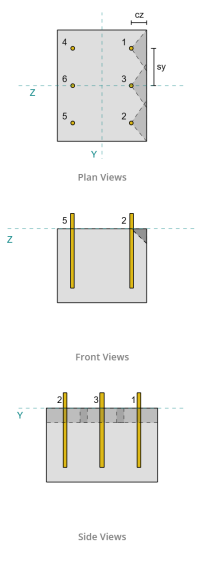
A falha ao longo da borda paralela à carga também é possível nesse cenário, Então o capacidade de fuga de concreto para a borda paralela deve ser determinado. As âncoras ou o grupo âncora considerados estão alinhados com a borda paralela. Consequentemente, a CA1 A distância da borda é medida da âncora para a borda ao longo da direção z. Com base na figura abaixo, as projeções do cone de falha se sobrepõem; Portanto, As âncoras são tratadas como um grupo.
Caso 1:
Caso 2:
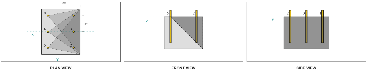
Nós nos referimos a ACI 318-19 Figura. R17.7.2.1b Para os diferentes casos utilizados ao avaliar grupos de âncora. Neste design da placa de base, arruelas de placas soldadas são usados especificamente. Portanto, só Caso 2 está verificado.
A carga necessária para o grupo âncora, no caso 2 é tomado como o Carga total de cisalhamento.
\( V_{fa paralelo,case2} = V_y = 2 , text{kip} \)
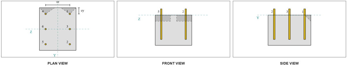
Ao calcular a capacidade do caso 2 falha, as âncoras consideradas são as âncoras traseiras. Como um resultado, A distância da borda CA1 é medida do grupo âncora traseiro até a borda de falha.
Com esta orientação a distância e borda CA1, deve -se verificar se o suporte se qualifica como um membro estreito. Seguindo ACI 318-19 Cláusula 17.7.2.1.2, O software da placa de base skyciv identificou o suporte como estreito. Portanto, a Distância CA1 modificada é usado, que é calculado para ser 6.667 no.
Os mesmos passos que no caso perpendicular são seguidos: calculando o Áreas de falha projetadas, a Força básica de fuga de âncora única, quanto pelo Parâmetros de quebra. Os valores calculados para cada etapa são mostrados abaixo.
\( UMA_{Vco} = 4.5 (c_{‘A1, G2})A partir da elevação do solo gerada a partir das elevações do Google 4.5 \vezes (6.6667\,\texto{no})^2 = 200 , text{no}^ 2 \)
\( UMA_{Vc} = B_{Vc} a força de deslizamento é a soma da força horizontal resultante da pressão ativa do solo no lado ativo do solo e a força horizontal resultante da presença da sobrecarga{Vc} = 14 , text{no} \vezes 10 , texto{no} = 140 , text{no}^ 2 \)
\( V_{b1} = 7.0733 , text{kip} \)
\( V_{b2} = 8.4853 , text{kip} \)
\( V_b = min(V_{b1},\, V_{b2}) = min(7.0733\,\texto{kip},\, 8.4853\,\texto{kip}) = 7.0733 , text{kip} \)
\( \Psi_{ed,V} = 1.0 \)
\( \Psi_{h,V} = 1.0 \)
A equação para a capacidade de borda paralela difere da capacidade da borda perpendicular. ACI 318-19 Cláusula 17.7.2.1(c) é aplicado, Onde a equação de fuga está multiplicado por 2.
\( \phi V_{CBG Parallel} = 2 \phi esquerda( \fratura{UMA_{Vc}}{UMA_{Vco}} \direito) \Psi_{ed,V} \Psi_{c,V} \Psi_{h,V} V_b \)
\( \phi V_{CBG Parallel} = 2 \vezes 0.65 \times left( \fratura{140\,\texto{no}^ 2}{200\texto{no}^ 2} \direito) \vezes 1 \vezes 1 \vezes 1 \Times 7.0733 , text{kip} = 6.4367 , text{kip} \)
A capacidade calculada para Vy cisalhamento no paralelo direção é 6.43 kips.
Agora avaliamos as falhas perpendiculares e paralelas separadamente.
- Para a falha da borda perpendicular, optimizada 0.33 kip < 0.56 kip, A capacidade de cisalhamento de concreto de design é suficiente.
- Para a falha da borda paralela, optimizada 2 kip < 6.43 kip, A capacidade de cisalhamento de concreto de design é suficiente.
Verificar #3: Calcule a capacidade de fuga de concreto devido ao cisalhamento VZ
A placa de base também é submetida a Vz cisalhamento, Portanto, as bordas de falha perpendiculares e paralelas ao cisalhamento da VZ devem ser verificadas. Usando a mesma abordagem, As capacidades perpendiculares e paralelas são calculadas como 2.45 kips e 1.26 kips, respectivamente.
Borda perpendicular:
Borda paralela:
Essas capacidades são então comparadas aos pontos fortes necessários.
- Para a falha da borda perpendicular, optimizada 2 kip < 2.45 kip, A capacidade de fuga de cisalhamento de concreto é suficiente.
- Para a falha da borda paralela, optimizada 0.33 kip < 1.26 kip, A capacidade de fuga de cisalhamento de concreto é suficiente.
Verificar #4: Calcule a capacidade de pryout concreto
A Cone de concreto para falha de pryout é o mesmo cone usado na verificação de ruptura da tração. Para calcular a capacidade de piruosas de cisalhamento, A força de ruptura da tração nominal das âncoras ou do grupo âncora deve ser determinado primeiro. Os cálculos detalhados para a verificação de quebra de tração já estão cobertos no Exemplos de design de Skyciv para carga de tensão.
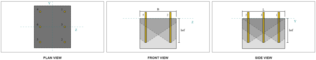
É importante observar que a determinação do grupo âncora para o cisalhamento é diferente daquele para a fuga de cisalhamento. Portanto, As âncoras no design ainda devem ser verificadas para determinar se elas agir seção retangular de madeira padronizada de acordo com grupo ou como âncoras únicas Contra o fracasso do Shear Pryout. A classificação do suporte como um Seção estreita também deve ser verificado e deve seguir as mesmas condições usadas para Ruptura de tensão.
Dos cálculos de Skyciv, a força de fuga de tração nominal do grupo âncora é 12.772 kips. Com um fator de ardilão de KCP = 2, A capacidade de design do design é:
\( \phi V_{cpg} = hy k_{cp} N_{cbg} = 0.65 \vezes 2 \vezes 12.772 \,\texto{kip} = 16.604 , text{kip} \)
A força necessária é o resultante das cargas de cisalhamento aplicadas. Como todas as âncoras pertencem a um único grupo, O cisalhamento resultante total é atribuído ao grupo.
\( V_{fazer} = sqrt{(V_y)^ 2 + (V_z)^ 2} = sqrt{(2\,\texto{kip})^ 2 + (2\,\texto{kip})^ 2} = 2.8284 , text{kip} \)
\( V_{fazer} = left( \fratura{V_{fazer}}{n / D} \direito) n_{uma,G1} = left( \fratura{2.8284\,\texto{kip}}{6} \direito) \vezes 6 = 2.8284 , text{kip} \)
Como a carga total de cisalhamento é menor que a capacidade do grupo âncora, 2.82 kips < 18.976 kips, A capacidade de design do design é suficiente.
Verificar #5: Calcule a capacidade de cisalhamento da haste de ancoragem
Lembre -se disso neste exemplo de design, O cisalhamento é distribuído a todas as âncoras. A carga total de cisalhamento por âncora é, portanto, resultante de sua parte da carga VY e sua parte da carga VZ.
\( v_{fazer,Y} = frac{V_y}{n / D} = frac{2\,\texto{kip}}{6} = 0,33333 , text{kip} \)
\( v_{fazer,z} = frac{V_z}{n / D} = frac{2\,\texto{kip}}{6} = 0,33333 , text{kip} \)
\( V_{fazer} = sqrt{(v_{fazer,Y})^ 2 + (v_{fazer,z})^ 2} \)
\( V_{fazer} = sqrt{(0.33333\,\texto{kip})^ 2 + (0.33333\,\texto{kip})^ 2} = 0,4714 , text{kip} \)
Isso dá o tensão de cisalhamento na haste da ancoragem como:
\( f_v = frac{V_{fazer}}{UMA_{haste}} = frac{0.4714\,\texto{kip}}{0.19635\,\texto{no}^ 2} = 2.4008 , text{ksi} \)
Porque uma arruela de placa está presente, a Carga excêntrica de cisalhamento é induzido na haste da ancoragem. A excentricidade é tomada como metade da distância medida do topo do suporte de concreto ao centro da arruela de placa, representando a espessura da placa de base. Consulte Guia de projeto AISC 1, 3Seção de edição RD 4.3.3.
\( e = 0.5 \deixou( \fratura{t_{pw}}{2} + t_{pb} \direito) = 0.5 \times left( \fratura{0.25\,\texto{no}}{2} + 0.75\,\texto{no} \direito) = 0,4375 , text{no} \)
O momento do cisalhamento excêntrico é então expresso como um estresse axial na haste de ancoragem. Usando o módulo de seção, a tensão axial devido a este momento é calculada como:
\( Z_{haste} = frac{\pi}{32} (d_a)^3 = frac{\pi}{32} \vezes (0.5\,\texto{no})^3 = 0,012272 , text{no}^ 3 \)
\( f_t = frac{V_{fazer} e}{Z_{haste}} = frac{0.4714\,\texto{kip} \vezes 0,4375 , text{no}}{0.012272\,\texto{no}^ 3} = 16.806 , text{ksi} \)
Capacidade de cisalhamento da haste da ancora ACI:
Seguindo ACI 318-19 Cláusula 17.7.1, A força do projeto é então determinada. A 0.8 fator de redução é aplicado devido à presença de almofadas de rejunte. A capacidade de design é, portanto,:
\( \phi V_{para,aqui} = 0.8 \phi 0.6 UMA_{eu sei,v} f_{uta} = 0.8 \vezes 0.65 \vezes 0.6 \vezes 0,1419 texto{no}^2 Times 90 Text{ksi} = 3.9845 texto{kip} \)
Como uma alternativa, a Software de placa de base Skyciv permite o 0.8 simplificação a ser desativada, e use a espessura real da almofada de rejunte nos cálculos. Nesse caso, A excentricidade total inclui a almofada de rejunte, e o cisalhamento combinado e a força axial são determinados de acordo com as disposições do AISC.
Capacidade de cisalhamento da haste da âncora da AISC:
Primeiro, a tensões nominais de cisalhamento e tração são determinados para uma haste A325.
\( F_{novo} = 0.45 F_{você,anc} = 0.45 \vezes 120\ \texto{ksi} = 54\ \texto{ksi} \)
\( F_{não} = 0.75 F_{você,anc} = 0.75 \vezes 120\ \texto{ksi} = 90\ \texto{ksi} \)
O método AISC usa AISC 360-22 Eq. J3-3a, que podem ser expressos para incluir os efeitos do estresse axial. Isso é realizado da seguinte maneira.
\( F'_{novo} = min left( 1.3 F_{novo} – \deixou( \fratura{F_{novo}}{\Phi f_{não}} \direito) f_t,\; F_{novo} \direito) \)
\( F'_{novo} = min left( 1.3 \vezes 54\ \texto{ksi} – \deixou( \fratura{54\ \texto{ksi}}{0.75 \vezes 90\ \texto{ksi}} \direito) \vezes 16.806\ \texto{ksi},\; 54\ \texto{ksi} \direito) = 54\ \texto{ksi} \)
A capacidade de cisalhamento do projeto do método AISC é então calculada como:
\( \phi R_{n,\Mathrm{aisc}} = Phi f'_{novo} UMA_{haste} = 0.75 \vezes 54\ \texto{ksi} \vezes 0.19635\ \texto{no}A partir da elevação do solo gerada a partir das elevações do Google 7.9522\)
Para garantir que ambos os métodos sejam cobertos, a capacidade de governo é tomada como a menor dos dois, qual é 3.98 kip.
\( \Phi v_n = min esquerda( \phi V_{para,aqui},\; \phi R_{n,\Mathrm{aisc}} \direito) = min (3.9845\ \texto{kip},\; 7.9522\ \texto{kip}) = 3.9845\ \texto{kip} \)
Como a carga de cisalhamento por haste de ancoragem é menor que a capacidade da haste de ancoragem que governa em cisalhamento, 0.47 kip < 3.98 kip, A capacidade de cisalhamento da haste da ancora de design é suficiente.
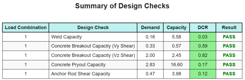
Resumo do projeto
A Software de design de placa de base skyciv pode gerar automaticamente um relatório de cálculo passo a passo para este exemplo de design. Ele também fornece um resumo dos cheques executados e suas proporções resultantes, facilitando o entendimento da informação. Abaixo está uma tabela de resumo de amostra, que está incluído no relatório.
Relatório de amostra de Skyciv
Veja o nível de detalhe e clareza que você pode esperar de um relatório de design de placa base SkyCiv. O relatório inclui todas as principais verificações de projeto, equações, e resultados apresentados em um formato claro e fácil de ler. É totalmente compatível com os padrões de design. Clique abaixo para ver um exemplo de relatório gerado usando a calculadora de placa base SkyCiv.
Compre software de placa de base
Compre a versão completa do módulo de design da placa de base por conta própria, sem outros módulos Skyciv. Isso oferece um conjunto completo de resultados para o design da placa de base, incluindo relatórios detalhados e mais funcionalidade.