Basisplatten -Design -Beispiel mit eN 1993-1-8:2005, IM 1993-1-1:2005, IM 1992-1-1:2004, und EN 1992-4:2018.
Problemanweisung
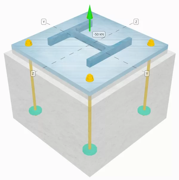
Bestimmen Sie, ob die konstruierte Säule-zu-Base-Plattenverbindung für eine Spannungsbelastung von 50 km ausreicht.
Gegebene Daten
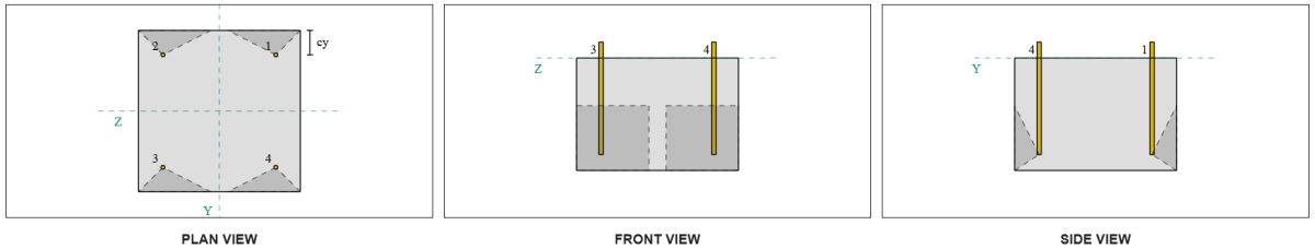
Spalte:
Spaltenabschnitt: ER 240 B.
Säulenbereich: 10600 mm2
Säulenmaterial: S235
Grundplatte:
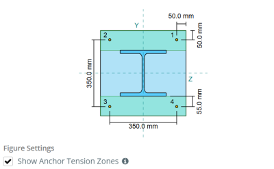
Grundplattenabmessungen: 450 mmx 450 mm
Grundplattendicke: 20 mm
Grundplattenmaterial: S235
Fugenmörtel:
Fugenmörtel Dicke: 20 mm
Beton:
Konkrete Abmessungen: 500 mmx 500 mm
Betondicke: 350 mm
Betonmaterial: C25/30
Geknackt oder ungekrönt: Geknackt
Anker:
Ankerdurchmesser: 12 mm
Effektive Einbettungslänge: 300.0 mm
Eingebetteter Plattendurchmesser: 60 mm
Dicke eingebetteter Platten: 10 mm
Ankermaterial: 8.8
Andere Informationen:
- Nicht-Counter-sunk-Anker.
- Anker mit geschnittenen Fäden.
Schweißnähte:
Schweißtyp: FPBW
Füllmetallklassifizierung: E35
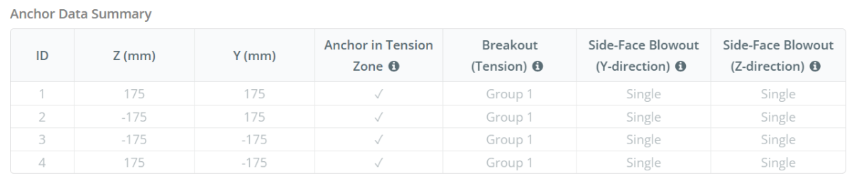
Ankerdaten (von Skyciv -Taschenrechner):
Modell im kostenlosen SkyCiv-Tool
Modellieren Sie noch heute das oben stehende Grundplattendesign mit unserem kostenlosen Online-Tool! Keine Anmeldung erforderlich.
Definitionen
Ankerspannungszone:
In dem SkyCiv Basisplatten-Design-Software, Nur Anker innerhalb der Ankerspannungszone werden als wirksam angesehen, um die Häufigkeit zu widerstehen. Diese Zone enthält typischerweise Bereiche in der Nähe der Spaltenflansche oder des Netzes. Anker außerhalb dieser Zone tragen nicht zum Spannungswiderstand bei und sind von den Anhebungsberechnungen ausgeschlossen.
Die Annahme vereinfacht die Grundplattenanalyse, indem sie sich annähert, wie sich die Erhöhungskraft durch die Platte ausbreitet.
Ankergruppen:
Mit der SkyCiv Basisplatten-Design-Software Enthält eine intuitive Funktion, die identifiziert, welche Anker Teil einer Ankergruppe für die Bewertung sind Betonausbruch und Beton-Seitenflächen-Blowout Fehler.
Ein Ankergruppe besteht aus mehreren Ankern mit ähnlichen effektiven Einbettungstiefen und Abstand, und sind nah genug, dass ihre Projizierte Widerstandsbereiche überlappen sich. Wenn Anker gruppiert sind, Ihre Kapazitäten werden kombiniert, um der Gesamtspannungskraft zu widerstehen, die der Gruppe angewendet wird.
Anker, die die Gruppierungskriterien nicht erfüllen, werden als behandelt einzelne Anker. In diesem Fall, Nur die Spannungskraft am individuellen Anker wird gegen seinen eigenen wirksamen Widerstandsbereich überprüft.
Schritt-für-Schritt-Berechnungen
Prüfen #1: Berechnen Sie die Schweißkapazität
Aus den gegebenen Informationen, Die in diesem Konstruktionsbeispiel verwendete Schweißnaht ist a Vollständig durchdringende Stumpfschweißung (FPBW). Wir berechnen die Grundmetallkapazitäten der Säule und der Grundplatte, um den Schweißwiderstand zu bestimmen. Um dies zu tun, Wir müssen zuerst die berechnen Gesamtschweißlänge auf der Säule und ermitteln Sie die Schweißspannung.
\(
F_{w,Ed} = frac{N_x}{2 b_f t_f + \links( d_{col} – 2 t_f – 2 r_{col} \richtig) t_w}
\)
\(
F_{w,Ed} = frac{50 \, \Text{kN}}{2 \mal 240 \, \Text{mm} \mal 17 \, \Text{mm} + \links( 240 \, \Text{mm} – 2 \mal 17 \, \Text{mm} – 2 \mal 21 \, \Text{mm} \richtig) \mal 10 \, \Text{mm}} = 5.102 \, \Text{MPa}
\)
Als nächstes, Wir bestimmen die Zugfestigkeit des schwächeren Materials zwischen der Säule und der Grundplatte.
\(
f_y = min left( f_{j,\Text{col}}, f_{j,\Text{bp}} \richtig) = min links( 225 \, \Text{MPa}, 225 \, \Text{MPa} \richtig) = 225 \, \Text{MPa}
\)
Wir verwenden dann IM 1993-1-8:2005 Klausel 4.7.1 und IM 1993-1-1:2005 Gl. 6.6 zur Berechnung des FPBW-Bemessungsschweißwiderstands.
\(
F_{w,Rd3} = frac{f_y}{\Um es zu berechnen{M0}} = frac{225 \, \Text{MPa}}{1} = 225 \, \Text{MPa}
\)
Schon seit 5.102 MPa < 225 MPa, Die Schweißkapazität ist ausreichend.
Prüfen #2: Berechnen Sie die Kapazität der Grundplattenflexus aufgrund der Spannungsbelastung
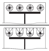
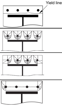
Zur Berechnung der Biegefähigkeit der Grundplatte gegen Zugbelastung, wir werden verwenden Fließlinienmuster wie kreisförmige Muster und nicht kreisförmige Muster. Dann, Wir bestimmen die Regierungsfähigkeit, vorausgesetzt, dass keine neugierigen Kräfte vorhanden sind, durch Vergleich der Streckgrenze der Platte mit dem Zugwiderstand der Ankerbolzen.
Anfangen, Wir berechnen das Erforderliche Abmessungen basierend auf der vorgegebenen Schraubenanordnung. Beziehen sich auf IM 1992-1-8:2005 Tabelle 6.2 zur Orientierung.
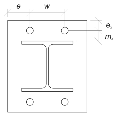
\(
m_x = frac{S_ – d_{col}}{2} = frac{350 \, \Text{mm} – 240 \, \Text{mm}}{2} = 55 \, \Text{mm}
\)
\(
w = s_z left( N_{ein,\Text{Seite}} – 1 \richtig) = 350 \, \Text{mm} \mal links( 2 – 1 \richtig) = 350 \, \Text{mm}
\)
\(
e_x = frac{L_{bp} – S_}{2} = frac{450 \, \Text{mm} – 350 \, \Text{mm}}{2} = 50 \, \Text{mm}
\)
\(
e = frac{B_{bp} – w}{2} = frac{450 \, \Text{mm} – 350 \, \Text{mm}}{2} = 50 \, \Text{mm}
\)
\(
b_p = B_{bp} = 450 \, \Text{mm}
\)
Berechnen wir auch den Randabstand des Ankers auf der Grundplatte, was durch die begrenzt ist \( m_x \) Dimension pro
\(
n = min left( ex, 1.25 m_x right) = min links( 50 \, \Text{mm}, 1.25 \mal 55 \, \Text{mm} \richtig) = 50 \, \Text{mm}
\)
Dann, Wir berechnen die effektiven Längen der folgenden kreisförmige Muster (beziehen auf SCI P398-Tabelle 5.3).
Kreisförmiges Muster 1:
\(
l_{eff,cp1} = n_{ein,\Text{Seite}} \pi m_x = 2 \mal pi times 55 \, \Text{mm} = 345.58 \, \Text{mm}
\)
Kreisförmiges Muster 2:
\(
l_{eff,cp2} = left( \frac{N_{ein,\Text{Seite}}}{2} \richtig) (\pi m_x + 2 ex) = left( \frac{2}{2} \richtig) \mal (\pi times 55 \, \Text{mm} + 2 \mal 50 \, \Text{mm}) = 272.79 \, \Text{mm}
\)
Maßgebendes kreisförmiges Muster effektive Länge:
\(
l_{eff,cp} = min (l_{eff,cp1}, l_{eff,cp2}) = min (345.58 \, \Text{mm}, 272.79 \, \Text{mm}) = 272.79 \, \Text{mm}
\)
Jetzt, Wir berechnen die effektiven Längen der folgenden nicht kreisförmige Muster (beziehen auf SCI P398-Tabelle 5.3)
Nicht kreisförmiges Muster 1:
\(
l_{eff,nc1} = frac{b_p}{2} = frac{450 \, \Text{mm}}{2} = 225 \, \Text{mm}
\)
Nicht kreisförmiges Muster 2:
\(
l_{eff,NC2} = left( \frac{N_{ein,\Text{Seite}}}{2} \richtig) (4 m_x + 1.25 ex) = left( \frac{2}{2} \richtig) \mal (4 \mal 55 \, \Text{mm} + 1.25 \mal 50 \, \Text{mm}) = 282.5 \, \Text{mm}
\)
Nicht kreisförmiges Muster 3:
\(
l_{eff,nc3} = 2 m_x + 0.625 ex + e = 2 \mal 55 \, \Text{mm} + 0.625 \mal 50 \, \Text{mm} + 50 \, \Text{mm} = 191.25 \, \Text{mm}
\)
Nicht kreisförmiges Muster 4:
\(
l_{eff,NC4} = 2 m_x + 0.625 ex + \frac{(N_{ein,\Text{Seite}} – 1) s_z}{2} = 2 \mal 55 \, \Text{mm} + 0.625 \mal 50 \, \Text{mm} + \frac{(2 – 1) \mal 350 \, \Text{mm}}{2} = 316.25 \, \Text{mm}
\)
Maßgebendes nicht-kreisförmiges Muster effektive Länge:
\(
l_{eff,nc} = min (l_{eff,nc1}, l_{eff,NC2}, l_{eff,nc3}, l_{eff,NC4}) = min (225 \, \Text{mm}, 282.5 \, \Text{mm}, 191.25 \, \Text{mm}, 316.25 \, \Text{mm}) = 191.25 \, \Text{mm}
\)
Dann, Wir bestimmen den kleineren Wert zwischen den effektiven Längen der kreisförmigen und nicht kreisförmigen Muster.
\(
l_{eff,1} = min (l_{eff,cp}, l_{eff,nc}) = min (272.79 \, \Text{mm}, 191.25 \, \Text{mm}) = 191.25 \, \Text{mm}
\)
Jetzt, Wir verwenden diese berechnete effektive Länge, um den Biegewiderstand zu berechnen. Gemäß IM 1993-1-8:2005 Tabelle 6.2, der Plattenmomentwiderstand für den Versagensmodus 1 ist:
\(
M_{pl,1,Rd} = frac{0.25 l_{eff,1} (t_{bp})^2 f_{und _bp}}{\Um es zu berechnen{M0}} = frac{0.25 \mal 191.25 \, \Text{mm} \mal (20 \, \Text{mm})^2 mal 225 \, \Text{MPa}}{1} = 4303.1 \, \Text{kN} \CDOT Text{mm}
\)
Vorausgesetzt kein neugieriges, wir verwenden EN 1993-1-8:2005 Tabelle 6.2 zu bestimmen Design Widerstand der Grundplatte für das Scheitern Modi 1 und 2.
\(
F_{T.,1,Rd} = frac{2 M_{pl,1,Rd}}{m_x} = frac{2 \mal 4303.1 \, \Text{kN} \CDOT Text{mm}}{55 \, \Text{mm}} = 156.48 \, \Text{kN}
\)
Dann, Wir berechnen den Zugwiderstand der Ankerstange anhand IM 1992-4:2018 Klausel 7.2.1.3. Dies wird in den folgenden Ankerprüfungen näher erläutert.
\(
F_{t,Rd} = frac{c k_2 F_{U _anc} Als}{\Um es zu berechnen{M2,Anker}} = frac{0.85 \mal 0.9 \mal 800 \, \Text{MPa} \mal 113.1 \, \Text{mm}^ 2}{1.25} = 55.372 \, \Text{kN}
\)
Wir werden dann den Widerstand pro Ankerstange verwenden, um den zu berechnen Bemessungswiderstand der Grundplatte unter Misserfolg Modus 3, Das ist der totale Schraubenausfall.
\(
F_{T.,3,Rd} = n_{ein,Seite} F_{t,Rd} = 2 \mal 55.372 \, \Text{kN} = 110.74 \, \Text{kN}
\)
Schließlich, Wir ermitteln den maßgeblichen Widerstandswert unter den Ausfallarten.
\(
F_{T.,Rd} = min (F_{T.,1,Rd}, F_{T.,3,Rd}) = min (156.48 \, \Text{kN}, 110.74 \, \Text{kN}) = 110.74 \, \Text{kN}
\)
Berechnen der Zugbelastung pro Flansch, wir haben:
\(
F_{T.,Ed} = frac{N_x}{2} = frac{50 \, \Text{kN}}{2} = 25 \, \Text{kN}
\)
Schon seit 25 kN < 110.74 kN, Die Grundkapazität der Grundplattenbiegung ist ausreichend.
Prüfen #3: Berechnen Sie die Ankerstange Zugkapazität
Den Wert für die Zugfestigkeit der Ankerstange kennen wir bereits, Aber lassen Sie uns das genauer angehen.
Zuerst, Berechnen wir die Zugspannungsfläche der Ankerstange.
\(
A_s = frac{\Pi}{4} (d_{anc})^2 = Frac{\Pi}{4} \mal (12 \, \Text{mm})^2 = 113.1 \, \Text{mm}^ 2
\)
Dann, Wenden wir die Werte für an \( c \) Faktor und die \( k_{2} \) Faktor. Diese Werte können in den Einstellungen der SkyCiv Base Plate Design-Software geändert werden. Probieren Sie die kostenlose Version hier aus.
- \( c = 0.85 \) für Anker mit geschnittenem Gewinde
- \( k_{2} = 0.9\) für nicht versenkte Anker
Jetzt, lasst uns verwenden IM 1992-4:2018 Klausel 7.2.1.3 um die zu berechnen Bemessungswiderstand der Ankerstange unter Spannung.
\(
N_{Rd,s} = frac{c k_2 F_{U _anc} Als}{\Um es zu berechnen{M2,Anker}} = frac{0.85 \mal 0.9 \mal 800 \, \Text{MPa} \mal 113.1 \, \Text{mm}^ 2}{1.25} = 55.372 \, \Text{kN}
\)
Berechnen der Spannungsbelastung pro Anker, wir haben:
\(
N_{Ed} = frac{N_x}{N_{ein,t}} = frac{50 \, \Text{kN}}{4} = 12.5 \, \Text{kN}
\)
Schon seit 12.5 kN < 55.372 kN, Die Ankerstange -Zugkapazität ist ausreichend.
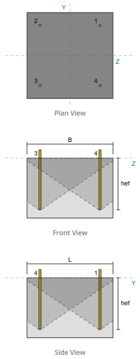
Prüfen #4: Berechnen Sie die Betonausbruchkapazität in der Spannung
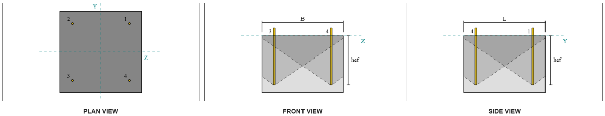
Vor der Berechnung der Ausbruchkapazität, Wir müssen zuerst feststellen, ob das Mitglied als qualifiziert ist enges Mitglied. Gemäß IM 1992-4:2008 Klausel 7.2.1.4(8), Das Mitglied erfüllt die Kriterien für ein enges Mitglied. Deshalb, ein verändert Effektive Einbettungslänge muss in den Ausbruchkapazitätsberechnungen verwendet werden. Diese Anpassung beeinflusst auch die charakteristischer Abstand und charakteristische Kantenabstand, das muss entsprechend geändert werden.
Basierend auf den schmalen Mitgliedskriterien, bleibt die Modifizierte Werte Für die Ankergruppe sind wie folgt:
- modifizierte effektive Einbettungslänge, \( H'_{ef} = 100 mm \)
- modifizierter charakteristischer Abstand, \( S'_{Einstellungen für Biege-Torsionsknicken} = 300 mm)
- modifizierter charakteristischer Kantenentfernung, \( C'_{Einstellungen für Biege-Torsionsknicken} = 150 mm)
Verwenden von IM 1992-4:2018 Gl. 7.3, wir berechnen die Referenz projizierter Betonkegelbereich für einen einzelnen Anker.
\(
A0_{c,N.} = s’_{Einstellungen für Biege-Torsionsknicken,G1} S'_{Einstellungen für Biege-Torsionsknicken,G1} = 350 \, \Text{mm} \mal 350 \, \Text{mm} = 122500 \, \Text{mm}^ 2
\)
Ähnlich, wir berechnen die Tatsächlicher projizierter Betonkegelbereich der Ankergruppe.
\(
EIN_{Nc} = L_{Nc} B_{Nc} = 500 \, \Text{mm} \mal 500 \, \Text{mm} = 250000 \, \Text{mm}^ 2
\)
Wo,
\(
L_{Nc} = min links( c_{links,G1}, C'_{Einstellungen für Biege-Torsionsknicken,G1} \richtig)
+ \links( \min links( S_{Summe,mit,G1}, S'_{Einstellungen für Biege-Torsionsknicken,G1} \links( N_{mit,G1} – 1 \richtig) \richtig) \richtig)
+ \min links( c_{richtig,G1}, C'_{Einstellungen für Biege-Torsionsknicken,G1} \richtig)
\)
\(
L_{Nc} = min links( 75 \, \Text{mm}, 175 \, \Text{mm} \richtig)
+ \links( \min links( 350 \, \Text{mm}, 350 \, \Text{mm} \mal (2 – 1) \richtig) \richtig)
+ \min links( 75 \, \Text{mm}, 175 \, \Text{mm} \richtig)
\)
\(
L_{Nc} = 500 \, \Text{mm}
\)
\(
B_{Nc} = min links( c_{oben,G1}, C'_{Einstellungen für Biege-Torsionsknicken,G1} \richtig)
+ \links( \min links( S_{Summe,j,G1}, S'_{Einstellungen für Biege-Torsionsknicken,G1} \links( N_{j,G1} – 1 \richtig) \richtig) \richtig)
+ \min links( c_{Unterseite,G1}, C'_{Einstellungen für Biege-Torsionsknicken,G1} \richtig)
\)
\(
B_{Nc} = min links( 75 \, \Text{mm}, 175 \, \Text{mm} \richtig)
+ \links( \min links( 350 \, \Text{mm}, 350 \, \Text{mm} \mal (2 – 1) \richtig) \richtig)
+ \min links( 75 \, \Text{mm}, 175 \, \Text{mm} \richtig)
\)
\(
B_{Nc} = 500 \, \Text{mm}
\)
Als nächstes, Wir bewerten die charakteristische Stärke eines einzelnen Ankers verwenden IM 1992-4:2018 Gl. 7.2
\(
N0_{Rk,c} = k_1 sqrt{\frac{f_{ck}}{\Text{MPa}}} \links( \frac{H'_{ef,G1}}{\Text{mm}} \richtig)^{1.5} N.
\)
\(
N0_{Rk,c} = 8.9 \mal sqrt{\frac{25 \, \Text{MPa}}{1 \, \Text{MPa}}} \mal links( \frac{116.67 \, \Text{mm}}{1 \, \Text{mm}} \richtig)^{1.5} \mal 0.001 \, \Text{kN} = 56.076 \, \Text{kN}
\)
Wo,
- \(k_{1} = 8.9\) für einbetonierte Anker
Jetzt, Wir bewerten die Auswirkungen der Geometrie, indem wir die erforderlichen Berechnung berechnen Parameter für Breakout -Widerstand.
Der kürzeste Randabstand der Ankergruppe wird als bestimmt als:
\(
c_{Min.,N.} = min links( c_{links,G1}, c_{richtig,G1}, c_{oben,G1}, c_{Unterseite,G1} \richtig)
= min links( 87.5 \, \Text{mm}, 87.5 \, \Text{mm}, 150 \, \Text{mm}, 150 \, \Text{mm} \richtig)
= 87.5 \, \Text{mm}
\)
Gemäß IM 1992-4:2018 Gl. 7.4, Der Wert für den Parameter zur Verteilung der Spannung in Beton ist:
\(
\Psi_{s,N.} = min links( 0.7 + 0.3 \links( \frac{c_{Min.,N.}}{C'_{Einstellungen für Biege-Torsionsknicken,G1}} \richtig), 1.0 \richtig)
= min links( 0.7 + 0.3 \mal links( \frac{75 \, \Text{mm}}{175 \, \Text{mm}} \richtig), 1 \richtig)
= 0.82857
\)
Mit der Shell Spalling -Effekt wird zur Verwendung berücksichtigt IM 1992-4:2018 Gl. 7.5, geben:
\(
\Psi_{Ausbruchkegelbereich für Einzeldübel nicht durch Kanten beeinflusst,N.} = min links( 0.5 + \frac{H'_{ef,G1}}{\Text{mm} \, / \, 200}, 1.0 \richtig)
= min links( 0.5 + \frac{116.67 \, \Text{mm}}{1 \, \Text{mm} \, / \, 200}, 1 \richtig)
= 1
\)
Zusätzlich, beide Exzentrizitätsfaktor und das Druckeinflussfaktor werden als:
\(
\Psi_{ec,N.} = 1
\)
\(
\Psi_{M.,N.} = 1
\)
Wir kombinieren dann all diese Faktoren und bewerben uns AS 5216:2021 Gleichung 6.2.3.1 Um die zu bewerten Konstruktionskegelausbruchwiderstand entwerfen Für die Ankergruppe:
\(
N_{Rd,c} = frac{N0_{Rk,c} \links( \frac{EIN_{Nc}}{A0_{c,N.}} \richtig) \Psi_{s,N.} \Psi_{Ausbruchkegelbereich für Einzeldübel nicht durch Kanten beeinflusst,N.} \Psi_{ec,N.} \Psi_{M.,N.}}{\Um es zu berechnen{Mc}}
\)
\(
N_{Rd,c} = frac{56.076 \, \Text{kN} \mal links( \frac{250000 \, \Text{mm}^ 2}{122500 \, \Text{mm}^ 2} \richtig) \mal 0.82857 \mal 1 \mal 1 \mal 1}{1.5} = 63.215 \, \Text{kN}
\)
Mit der Gesamtspannungsbelastung Auf der Ankergruppe wird berechnet, indem die Spannungsbelastung pro Anker mit der Anzahl der Anker multipliziert wird:
\(
N_{Fa} = left( \frac{N_x}{N_{ein,t}} \richtig) N_{ein,G1} = left( \frac{50 \, \Text{kN}}{4} \richtig) \mal 4 = 50 \, \Text{kN}
\)
Schon seit 50 kN < 63.215 kN Die Betonausbruchkapazität ist ausreichend.
Prüfen #5: Berechnen Sie die Ankerauszugskapazität
Mit der Ausziehkapazität eines Ankers wird durch den Widerstand an seinem eingebetteten Ende bestimmt. Anwenden seismischer Lasten, wir berechnen die Lagerfläche der eingebetteten Platte, Dies ist die Nettofläche nach Abzug der von der Ankerstange eingenommenen Fläche.
Zuerst, Wir berechnen die maximale Ankerkopfdimension, die für den Auszugswiderstand wirksam ist, gemäß IM 1992-4:2018 Klausel 7.2.1.5 Hinweis.
\(
d_{h,\Text{max}} = min links( = Abstand des Abschnitts, in dem die Scherung berücksichtigt wird, zur Fläche des nächsten Auflagers{\Text{einbetten _plate}}, 6 \links( t_{\Text{einbetten _plate}} \richtig) + d_{\Text{anc}} \richtig)
= min links( 60 \, \Text{mm}, 6 \mal (10 \, \Text{mm}) + 12 \, \Text{mm} \richtig)
= 60 \, \Text{mm}
\)
Als nächstes, Wir berechnen die Nettotragfläche der kreisförmigen eingebetteten Platte mit:
\(
EIN_{brg} = frac{\Pi}{4} \links( \links( d_{h,\Text{max}} \richtig)^ 2 – \links( d_{\Text{anc}} \richtig)^2 rechts)
\)
\(
EIN_{brg} = frac{\Pi}{4} \mal links( \links( 60 \, \Text{mm} \richtig)^ 2 – \links( 12 \, \Text{mm} \richtig)^2 rechts) = 2714.3 \, \Text{mm}^ 2
\)
Wir berechnen dann die Bemessung des Betonauszugswiderstands des einbetonierten Ankers unter Zugbeanspruchung IM 1992-4:2018 Klausel 7.2.1.5:
\(
N_{Rd,s} = frac{k_2 A_{brg} f_{ck}}{\Um es zu berechnen{MP}}
= frac{7.5 \mal 2714.3 \, \Text{mm}^2 mal 25 \, \Text{MPa}}{1.5}
= 339.29 \, \Text{kN}
\)
Erinnern Sie sich an die zuvor berechneten Spannungsbelastung pro Anker:
\(
N_{Ed} = frac{N_x}{N_{ein,t}} = frac{50 \, \Text{kN}}{4} = 12.5 \, \Text{kN}
\)
Schon seit 12.5 kN < 339.29 kN, Die Ankerauszugskapazität ist ausreichend.
Prüfen #6: Berechnen Sie die Blowout-Kapazität der Seitengesicht in der y-Richtung

Betrachten wir die Anker-ID #3. Wir beginnen mit der Berechnung des Kantenabstands zur Fehlerkante.
\(
c_{mit,\Text{Min.}} = min links( c_{\Text{links,s3}}, c_{\Text{richtig,s3}} \richtig)
= min links( 75 \, \Text{mm}, 425 \, \Text{mm} \richtig)
= 75 \, \Text{mm}
\)
Als nächstes, Wir bestimmen den Randabstand zum orthogonale Kante.
\(
c_{j,\Text{Min.}} = min links( c_{\Text{oben,s3}}, c_{\Text{Unterseite,s3}} \richtig)
= min links( 425 \, \Text{mm}, 75 \, \Text{mm} \richtig)
= 75 \, \Text{mm}
\)
Verwenden von IM 1992-4:2018 Gl. 7.27, Berechnen wir die Referenz projizierter Bereich eines einzelnen Befestigers.
\(
A0_{c,NB} = left( 4 c_{mit,\Text{Min.}} \richtig)^ 2
= left( 4 \mal 75 \, \Text{mm} \richtig)^ 2
= 90000 \, \Text{mm}^ 2
\)
Da wir die Kapazität der Ankergruppe überprüfen, Lass uns das bekommen Tatsächlicher projizierter Bereich der Ankergruppe verwenden IM 1992-4:2018 Gl. 7.27.
\(
EIN_{Nc} = B_{c,NB} Um es zu berechnen{c,NB} = 225 \, \Text{mm} \mal 200 \, \Text{mm} = 45000 \, \Text{mm}^ 2
\)
Wo,
\(
B_{c,NB} = 2 c_{mit,\Text{Min.}} + \min links( 2 c_{mit,\Text{Min.}}, c_{j,\Text{Min.}} \richtig)
= 2 \mal 75 \, \Text{mm} + \min links( 2 \mal 75 \, \Text{mm}, 75 \, \Text{mm} \richtig)
= 225 \, \Text{mm}
\)
\(
Um es zu berechnen{c,NB} = 2 c_{mit,\Text{Min.}} + \links( \min links( t_{\Text{konz}} – h_{\Text{ef}}, 2 c_{mit,\Text{Min.}} \richtig) \richtig)
= 2 \mal 75 \, \Text{mm} + \links( \min links( 350 \, \Text{mm} – 300 \, \Text{mm}, 2 \mal 75 \, \Text{mm} \richtig) \richtig)
= 200 \, \Text{mm}
\)
In der Berechnung der charakteristische konkrete Ausbruchstärke eines individuellen Ankers, wir werden verwenden IM 1992-4:2018 Gl. 7.26.
\(
N0_{Rk,cb} = k_5 links( \frac{c_{mit,\Text{Min.}}}{\Text{mm}} \richtig)
\links( \sqrt{\frac{EIN_{\Text{brg}}}{\Text{mm}^ 2}} \richtig)
\links( \sqrt{\frac{f_{ck}}{\Text{MPa}}} \richtig) N.
\)
\(
N0_{Rk,cb} = 8.7 \mal links( \frac{75 \, \Text{mm}}{1 \, \Text{mm}} \richtig)
\mal links( \sqrt{\frac{2714.3 \, \Text{mm}^ 2}{1 \, \Text{mm}^ 2}} \richtig)
\mal links( \sqrt{\frac{25 \, \Text{MPa}}{1 \, \Text{MPa}}} \richtig)
\mal 0.001 \, \Text{kN}
\)
\(
N0_{Rk,cb} = 169.97 \, \Text{kN}
\)
Dann, Wir werden das bekommen Seitengesichtsparameter.
Der Parameter, der die Störung der Verteilung von Spannungen in Beton ausgeht, kann berechnet werden IM 1992-4:2018 Gl. 7.28.
\(
\Psi_{s,NB} = min links( 0.7 + 0.3 \links( \frac{c_{j,\Text{Min.}}}{2 c_{mit,\Text{Min.}}} \richtig), 1.0 \richtig)
= min links( 0.7 + 0.3 \mal links( \frac{75 \, \Text{mm}}{2 \mal 75 \, \Text{mm}} \richtig), 1 \richtig)
= 0.85
\)
Zusätzlich, Die Faktoren für den Gruppeneffekt und der Faktor für den Einfluss der Exzentrizität sind wie folgt:
\(
\Psi_{G,NB} = 1
\)
\(
\Psi_{ec,N.} = 1
\)
Schließlich, in Bezug auf AS 5216:2021 Gl. 6.2.7 Für Kopf -Ankerstangen, bleibt die Konstruktion konstruiere Ausbruchwiderstand ist:
\(
N_{Rk,cb} = frac{N0_{Rk,cb} \links( \frac{EIN_{Nc}}{A0_{c,NB}} \richtig) \links( \Psi_{s,NB} \richtig) \links( \Psi_{G,NB} \richtig) \links( \Psi_{ec,N.} \richtig)}{\Um es zu berechnen{Mc}}
\)
\(
N_{Rk,cb} = frac{169.97 \, \Text{kN} \mal links( \frac{45000 \, \Text{mm}^ 2}{90000 \, \Text{mm}^ 2} \richtig) \mal links( 0.85 \richtig) \mal links( 1 \richtig) \mal links( 1 \richtig)}{1.5} = 48.159 \, \Text{kN}
\)
Abrufen Spannungsbelastung pro Anker:
\(
N_{Ed} = frac{N_x}{N_{ein,t}} = frac{50 \, \Text{kN}}{4} = 12.5 \, \Text{kN}
\)
Schon seit 12.5 kN < 48.159 kN, Der Beton-Seitenflächen-Blowout entlang der Y-Region ist ausreichend.
Jede andere Anker-ID-Nummer kann ebenfalls verwendet werden und führt zum gleichen Ergebnis, Da ist das Design symmetrisch.
Prüfen #7: Berechnen Sie die Blowout-Kapazität der Seitengesicht in der Z-Richtung
Das gleiche Verfahren wird bei der Berechnung der Kapazität für das seitliche Ausblasen in Z-Richtung verwendet. Betrachten wir die Anker-ID #2 diesmal. Nochmal, Wir beginnen mit der Berechnung des Randabstands zum Fehlerkante.
\(
c_{j,\Text{Min.}} = min links( c_{\Text{oben},s2}, c_{\Text{Unterseite},s2} \richtig)
= min links( 75 \, \Text{mm}, 425 \, \Text{mm} \richtig)
= 75 \, \Text{mm}
\)
Als nächstes, Wir bestimmen den Randabstand zum orthogonale Kante.
\(
c_{mit,\Text{Min.}} = min links( c_{\Text{links},s2}, c_{\Text{richtig},s2} \richtig)
= min links( 75 \, \Text{mm}, 425 \, \Text{mm} \richtig)
= 75 \, \Text{mm}
\)
Verwenden von IM 1992-4:2018 Gl. 7.27, Berechnen wir die Referenz projizierter Bereich eines einzelnen Befestigers.
\(
A0_{c,NB} = left( 4 c_{j,\Text{Min.}} \richtig)^ 2
= left( 4 \mal 75 \, \Text{mm} \richtig)^ 2
= 90000 \, \Text{mm}^ 2
\)
Da wir die Kapazität der Ankergruppe überprüfen, Lass uns das bekommen Tatsächlicher projizierter Bereich der Ankergruppe verwenden IM 1992-4:2018 Gl. 7.27.
\(
EIN_{Nc} = B_{c,NB} Um es zu berechnen{c,NB}
= 225 \, \Text{mm} \mal 200 \, \Text{mm}
= 45000 \, \Text{mm}^ 2
\)
Wo,
\(
B_{c,NB} = 2 c_{j,\Text{Min.}} + \min links( 2 c_{j,\Text{Min.}}, c_{mit,\Text{Min.}} \richtig)
= 2 \mal 75 \, \Text{mm} + \min links( 2 \mal 75 \, \Text{mm}, 75 \, \Text{mm} \richtig)
= 225 \, \Text{mm}
\)
\(
Um es zu berechnen{c,NB} = 2 c_{j,\Text{Min.}} + \links( \min links( t_{\Text{konz}} – h_{\Text{ef}}, 2 c_{j,\Text{Min.}} \richtig) \richtig)
= 2 \mal 75 \, \Text{mm} + \links( \min links( 350 \, \Text{mm} – 300 \, \Text{mm}, 2 \mal 75 \, \Text{mm} \richtig) \richtig)
= 200 \, \Text{mm}
\)
In der Berechnung der charakteristische konkrete Ausbruchstärke eines individuellen Ankers, wir werden verwenden IM 1992-4:2018 Gl. 7.26.
\(
N0_{Rk,cb} = k_5 links( \frac{c_{j,\Text{Min.}}}{\Text{mm}} \richtig)
\sqrt{\links( \frac{EIN_{brg}}{\Text{mm}^ 2} \richtig)}
\sqrt{\links( \frac{f_{ck}}{\Text{MPa}} \richtig)} \, \Text{N.}
\)
\(
N0_{Rk,cb} = 8.7 \links( \frac{75 \, \Text{mm}}{1 \, \Text{mm}} \richtig)
\sqrt{\links( \frac{2714.3 \, \Text{mm}^ 2}{1 \, \Text{mm}^ 2} \richtig)}
\sqrt{\links( \frac{25 \, \Text{MPa}}{1 \, \Text{MPa}} \richtig)}
\Unterbau Erde 0.001 \, \Text{kN}
\)
\(
N0_{Rk,cb} = 169.97 \, \Text{kN}
\)
Dann, Wir werden das bekommen Seitengesichtsparameter.
Der Parameter, der die Störung der Verteilung von Spannungen in Beton ausgeht, kann berechnet werden IM 1992-4:2018 Gl. 7.28.
\(
\Psi_{s,NB} = min links( 0.7 + 0.3 \links( \frac{c_{mit,\Text{Min.}}}{2 c_{j,\Text{Min.}}} \richtig), 1.0 \richtig)
= min links( 0.7 + 0.3 \mal links( \frac{75 \, \Text{mm}}{2 \mal 75 \, \Text{mm}} \richtig), 1 \richtig)
= 0.85
\)
Zusätzlich, Die Faktoren für den Gruppeneffekt und der Faktor für den Einfluss der Exzentrizität sind wie folgt:
\(
\Psi_{G,NB} = 1
\)
\(
\Psi_{ec,N.} = 1
\)
Schließlich, in Bezug auf AS 5216:2021 Gl. 6.2.7 Für Kopf -Ankerstangen, bleibt die Konstruktion konstruiere Ausbruchwiderstand ist:
Abrufen Spannungsbelastung pro Anker:
\(
N_{Ed} = frac{N_x}{N_{ein,t}} = frac{50 \, \Text{kN}}{4} = 12.5 \, \Text{kN}
\)
Schon seit 12.5 kN < 48.159 kN, Der Seitenflächenausbruch des Betons entlang der Z-Richtung beträgt ausreichend.
Jede andere Anker-ID-Nummer kann ebenfalls verwendet werden und führt zum gleichen Ergebnis, Da ist das Design symmetrisch.
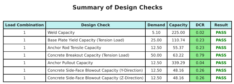
Entwurfszusammenfassung
Mit der Skyciv Base Plate Design Software kann automatisch einen Schritt-für-Schritt-Berechnungsbericht für dieses Entwurfsbeispiel erstellen. Es enthält auch eine Zusammenfassung der durchgeführten Schecks und deren resultierenden Verhältnisse, Die Informationen auf einen Blick leicht zu verstehen machen. Im Folgenden finden Sie eine Stichprobenzusammenfassungstabelle, Welches ist im Bericht enthalten.
SKYCIV -Beispielbericht
Sehen Sie sich den Detaillierungsgrad und die Klarheit an, die Sie von einem SkyCiv-Grundplatten-Designbericht erwarten können. Der Bericht umfasst alle wichtigen Designprüfungen, Gleichungen, und Ergebnisse werden in einem klaren und leicht lesbaren Format präsentiert. Es entspricht vollständig den Designstandards. Klicken Sie unten, um einen Beispielbericht anzuzeigen, der mit dem SkyCiv-Grundplattenrechner erstellt wurde.
Basisplattensoftware kaufen
Kaufen Sie die Vollversion des Basisplatten -Designmoduls selbst ohne andere Skyciv -Module selbst. Auf diese Weise erhalten Sie einen vollständigen Satz von Ergebnissen für die Basisplattendesign, Einbeziehung detaillierter Berichte und mehr Funktionen.